Disclaimers and Regulatory Information
This product complies with
all relevant European directives; for details, please see the separate
product specific Declaration of Conformity (DOC)
sheet.
 |
| |
| CALIFORNIA |
| |
| Proposition 65 |
| |
| Use of this product may cause
exposure to chemicals known to the
State of California to cause cancer, birth defects,
or other reproductive
harm. |
| |
Electromagnetic Compatibility
Certification
| Domestic: This device complies with FCC
Rules Part 15. Operation is subject to the following two conditions:
(1) This device may not cause
harmful interference and (2) this device must accept any interference
that may be received, including interference that
may cause undesirable operation.
|
| FCC ID: 2AC7Z-ESP32WROVERE; 2AET4RUT241AF IC: 21098-ESPS2WROVER; 26511-RUT241AF |
| This equipment has been tested
and found to comply within the limits for a Class B digital device,
pursuant to part 15 of the FCC
Rules. These limits are designed to provide reasonable protection
against harmful interference in a residential installation.
This equipment generates, uses, and
can radiate radio frequency energy and, if not installed and used
in accordance with the instructions,
may cause harmful interference to radio communications. However, there
is no guarantee that interference will
not occur in a particular installation. If this equipment
does cause harmful interference to radio or television reception,
which can be determined by turning
the equipment off and on, the user is encouraged to try to connect
the interference by one or more
of the following measures:
- Reorient or relocate the receiving
antenna.
- Increase the separation between
the equipment and receiver.
- Connect the equipment into an
outlet on a circuit different from that to which the receiver is connected.
- Consult the dealer or an experienced
radio/TV technician for help.
|
| Australia
|
New Zealand |
 |
 |
| Japan
|
|
 |
|
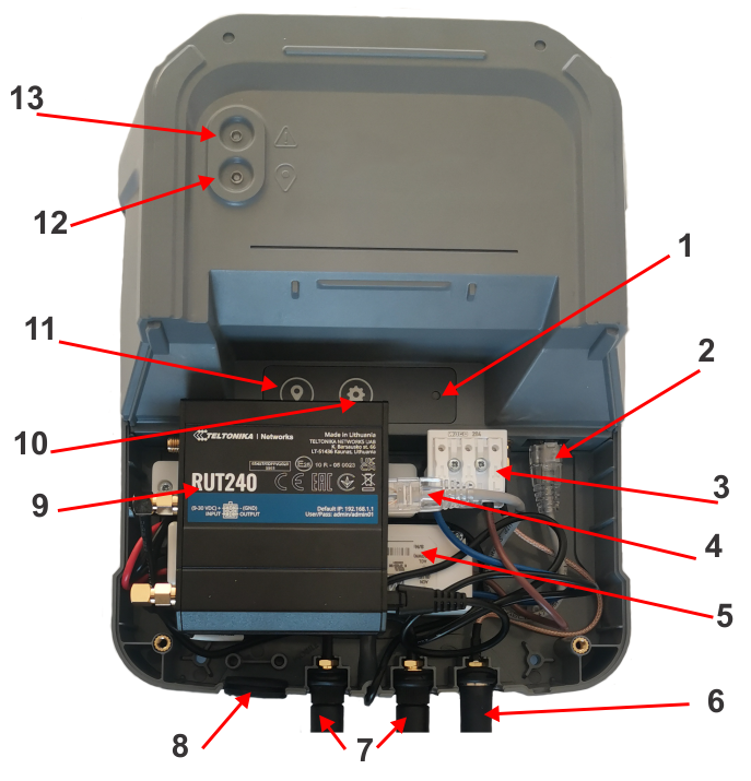
RTK Base Diagnostic Tool
This tool can be used with bases
that have software version 3.0 or higher. It provides information
that can aid in resolving problems concerning the
base.
Pre-requisites:
- A smartphone or laptop with Wi-Fi
and an internet connection.
- You must be in close proximity
to the base, since you need to connect to the Wi-Fi of the base.
Accessing the Diagnostic Tool
-
Power on
the RTK base.
-
If you are
using a smartphone, disable your mobile connection.
-
On the smartphone
or laptop connect to the Wi-Fi of the base: RTKWi-Fi.
-
Enter the
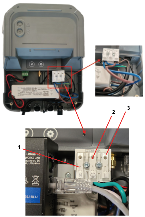
password for the Wi-Fi. The initial/default password is available
from the label on the side of the base station.
You are required to change
the password.
Note: The password MUST consist of 8 characters.
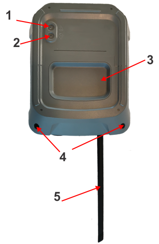
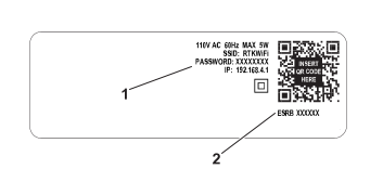
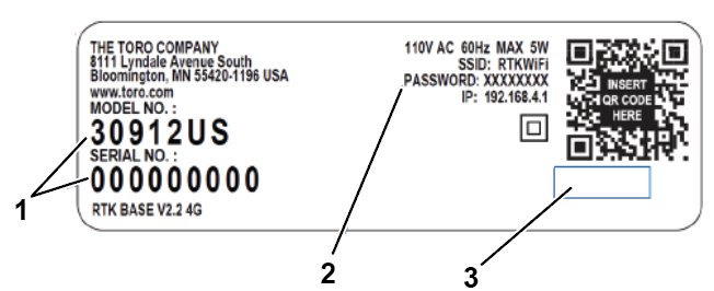
For serial numbers 324000000
through 324999999:
G539289
-
The initial/default password for
the base Wi-Fi
-
The serial number of the base
For serial numbers 325000000
and up: G542400
-
Base ID serial number Model-Serial
-
Initial/default password for the
base ID
-
Area blank
The initial/default
password is highlighted in the figure above and consists of 8 characters.
If you have changed the password, enter
the new one.
-
Open a web
browser and go to page: http://192.168.4.1. The RTK base diagnostic
page will open. The options presented depends
on whether the base is using Wi-Fi or 4G.
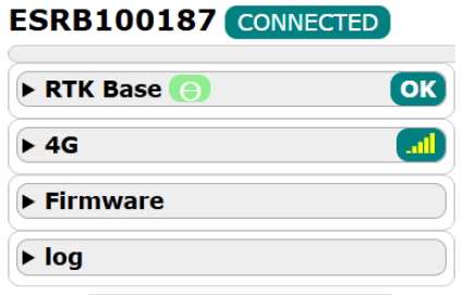
Overview
Base Serial Number
- The base serial number as shown
on the label.
Connected Status
- This indicates whether the base
is connected to the device you are using to access the diagnostic
tool.
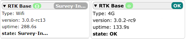
RTK Base
This page displays information
about the current status of the base:
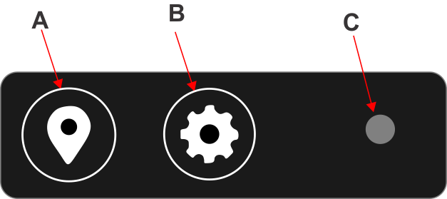
- Real time status LEDs
- Positioning (green) and Error
(red) LEDs
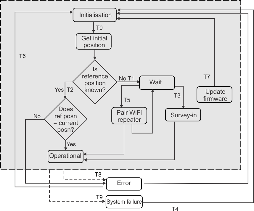
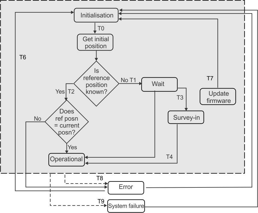
- Base functional state
This shows
the current functional state of the base. Possible values are:
- OK
- Initialization
- Get initial position
- Wait
- Survey-In
- Operational
- Error
- Pair repeater
- Update SW
Type
- The method used for transmitting
the corrections. This can be Wi-Fi or 4G.
Version
- The current software version.
Uptime
- The number of seconds that the
base has been operating since the last reset operation.
State
- The current functional state of
the base.
If the current
state is the error state, the type of error is displayed. Possible
values are:
- Position error
- GNSS antenna error
- Survey-in error
- Network error (4G)
- System failure
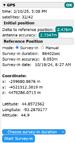
GPS
This page displays information
about the GPS performance and the base reference position. It enables
you to determine the reference position. The
details displayed on this page depends on the status of the base.
Status
- This corresponds to the overall
status of the base.
Time
- The current date (mm/dd/yyyy)
and time.
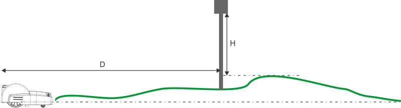
Satellites
- The number of satellites to which
the base is connected / number of satellites available. The base should
be connected to at least 10 satellites.
If this is not the case, you need to move the antenna.
Initial position
- This field appears when a reference
position has been determined. The initial position is the position
detected when the base starts up.
Delta to reference position
- The value displayed here is the
difference between the reference position and the initial position.
This needs to be within 7 m (23 ft) of
the reference position.
Antenna accuracy
- This is a factor describing the
accuracy of the base in determining its position. This needs to be
less than 1 m (3.2 ft) .
Reference Position
mode
- This sets the mode whereby the
reference position is set. This can be either:
- Survey-in: in this mode, the base will
determine its own reference position.
- Manual: in this mode, the reference
position is defined by entering the coordinates that were previously
determined.
Survey-in duration
- This field appears when the reference
position has been determined. It is the time period used for the survey-in.
Survey-in accuracy
- This field appears when the reference
position has been determined. It displays the accuracy at the termination
of the survey-in process, which will be
less than 7 m (23 ft).
Survey-in date
- Date on which the survey-in was
performed.
Coordinates
- These fields are displayed once
the reference position has been determined.
- X, Y, Z
The coordinates of the reference
position expressed in terms of ECEF (Earth-Centered, Earth-Fixed coordinate
system).
- Latitude, longitude, Altitude
The coordinates of the
reference position expressed in terms of the GCS (Geographic Coordinate
System).
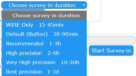
Choose survey-in duration
These
options allow you to choose the time that will be used for the survey-in
process:
- Start Survey-in
- Starts the process whereby the
base determines its reference position
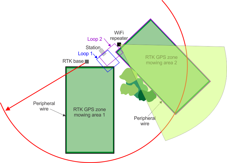
Determining the Base Reference
Position
This process can be used if a
new reference position is required.
-
Check the
Survey-in mode option.
-
Choose the
time to be used for the process. The longer the time, the more accurate
the determination of the position will
be. The shortest time available is WIRE Only 15-45min and can be used
if the installation includes a peripheral wire.
-
Press Start Survey-in. The base will contact the satellites
and determine its reference position. The current coordinates of the
reference position will be shown in the
Ongoing fields. The process will continue until the accuracy is less
than 7 m (23 ft). When the minimum amount
of time chosen has elapsed, a error will be generated and the process
will continue for two more time periods after
which another error will be generated. In this case, it will
be necessary to move the base or its antenna.
Manually Setting the Reference
Position for a 4G RTK Installation
This procedure
enables you to retrieve the coordinates of the reference position
that were determined during the discovery
and verification process. The base reference position is regarded
as having moved if the current coordinates differ by more
than 7m from the coordinates that were used for the
reference position. In the case of a 4G RTK installation, this difference
is automatically detected on the robot, and
the original coordinates can be retrieved from the robot. For an RTK
installation using a peripheral wire, the
difference is not automatically detected or communicated and the previous
coordinates can be retrieved from the web
portal. There is an advantage in retrieving the original reference
coordinates because it means that the mapping
the robot uses to calculate its working pattern do not have to be
adjusted.
-
On the robot,
select Technician's menu (9) > Infrastructure > Parcels > 4G RTK SUMMARY.
This will show the message X RTK Base MOVED.
-
Click on MOVED.
-
Click on 4G RTK Base.
-
In the diagnostic
tool check the Manual mode option.
-
Copy the
coordinates shown on the robot UI.
-
Press Save.
Manually Setting the Reference
Position for a Wired RTK Installation
-
Go to the turfpro.toro.com web portal.
-
Select the
robot you are interested in and click on Parameters.
-
Select the
Robot Activity tab and click on L at the top of the page.
-
In the "Events"
column, select the event type "RTKSVinChange". You will be presented
with values for the previous and the new
values of X, Y and Z.
-
Copy the
previous values for X, Y and Z into the diagnostics tool.
-
Click Save.
-
Restart the
robot.
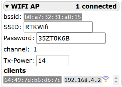
Wi-Fi AP
This page provides information
about the base Wi-Fi. It also enables you to change the Wi-Fi password
and the channel used for the Wi-Fi communication.
{X} Connected
- The number of clients (robots)
connected to the Wi-Fi of the base.
bssid
- The BSSID of the base Wi-Fi.
SSID
Password
- This field will display the password
if one has been set. If this field is empty, it means that no password
has been defined. Details on changing the
password are given in the following section. You are required to set a new
password.
Channel
- This is the Wi-Fi frequency band
used by the RTK base. The default is channel is 1. If the robot is
finding that the Wi-Fi coverage is not
sufficient over the entire site, and is stopping working because the
GPS signal is lost, this may be due to
the presence of other Wi-Fi devices near the site which are interfering
with the communication between the base and the robot.
In this case, you can change the channel used to one
that has more capacity than the current one. A recommended app to
show the usage of the Wi-Fi channels in
the vicinity of the base is Wi-Fi Analyzer.
If you change
the channel, you need to re-pair the Wi-Fi repeater.
The remaining
fields are used for technical purposes.
Changing the Wi-Fi Password
After changing the Wi-Fi password,
the connection to the base Wi-Fi will be lost. You will need to re-connect
to the base using the new password.
-
Click in
the Password field.
-
Enter a new
password. The background color will change to orange.
Note: This must contain at least 8 characters.
-
Press Save.
Note: It is recommended that you make a note of the password and keep it
safe.
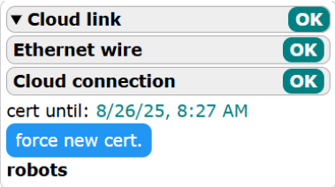
Cloud Link
Note: This page is only available if 4G is being used for data corrections.
This page provides information
regarding connectivity of the base to the RTK base web server.
Cloud
link
- The status value shown here depends
on the status of the two fields shown below.
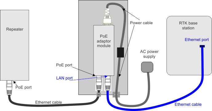
Ethernet wire
- The Ethernet wire needs to be
properly connected.
Cloud connection
- Connection to RTK base web server.
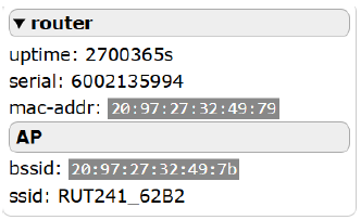
Router
Uptime
- The time in seconds since the
router was started.
Serial
- The serial number of the router.
Mac-addr
- The MAC address of the router
AP
- The bssid and the ssid of the
router
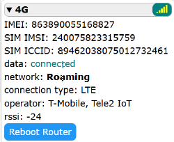
4G
Note: This page is only available if 4G is being used for data corrections.
Signal level
- The strength of the 4G signal
level.
Uptime
- Time in seconds since the last
reboot of the router.
IMEI
- This information is displayed
for technical purposes.
SIM IMSI
- This information is displayed
for technical purposes.
SIM ICCID
- This information is displayed
for technical purposes.
Network
- This information is displayed
for technical purposes.
Connection type
Operator
Reboot Router
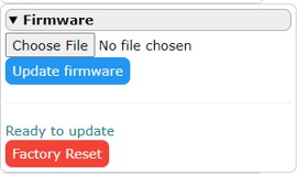
Firmware
This page enables you to perform
a software update using a binary file and a factory reset. The current
software version can be seen on the RTK base
page.
Choose file
- This enables you to perform a
firmware update using a binary file. This option is not currently
supported.
Update firmware
- Updates the base firmware.
Factory reset
- Pressing this button will perform
a factory reset. As a result of a factory reset:
- All configuration parameters are
lost
- The reference (survey-in) position
is lost
- For a base delivered with firmware
version 3.0, the password will be reset to the default one shown on
the label
- For a base delivered with an firmware
version lower than 3.0, the password will be cleared and the Wi-Fi
will become open
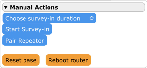
Manual Actions
This page enables you to perform
functions without the need for physical access to buttons in base.
Choose survey-in duration
This
enables you to choose the length of time you want to use for the survey-in
process. A list of options appears. The longer
the duration chosen the higher the accuracy by which the reference
position will be determined.
- "Wire Only 15-45min" can be used
if the installation includes a peripheral wire.
Start Survey-in
- This starts Survey-in process
to determine the reference position of the base. The base needs to
be in Wait, Operational or Error states.
Pair Repeater
- This allows you to pair the base
with a Wi-Fi Repeater. The base needs to be in Wait, Operational,
or Error states.
Reset base
- This powers the base off, then
on. All configuration parameters are retained.
Reboot router
- This powers the 4G router off,
then on. All configuration parameters are retained. This operation
is useful If it is blocked; no internet
for example.
California Proposition 65 Warning
Information
What is this warning?
You may see
a product for sale that has a warning label like the following:
 |
WARNING: Cancer and Reproductive Harm—www.p65Warnings.ca.gov. |
What is Prop 65?
Prop 65 applies
to any company operating in California, selling products in California,
or manufacturing products that may be sold in or
brought into California. It mandates that the Governor of California
maintain and publish a list of chemicals known to
cause cancer, birth defects, and/or other reproductive harm. The list,
which is updated annually, includes hundreds of
chemicals found in many everyday items. The purpose of Prop 65 is
to inform the public about exposure to these chemicals.
Prop 65 does not ban the sale
of products containing these chemicals but instead requires warnings
on any product, product packaging, or literature
with the product. Moreover, a Prop 65 warning does not mean that a
product is in violation of any product safety standards
or requirements. In fact, the California government has clarified
that a Prop 65 warning “is not the same as a regulatory
decision that a product is ‘safe’ or ‘unsafe.’” Many of these chemicals have been
used in everyday products for years without documented harm. For more
information, go to https://oag.ca.gov/prop65/faqs-view-all.
A Prop 65 warning means
that a company has either (1) evaluated the exposure and has concluded
that it exceeds the “no significant risk level”; or (2) has chosen to provide
a warning based on its understanding about the presence of a listed
chemical without attempting to evaluate the exposure.
Does this law apply everywhere?
Prop 65 warnings
are required under California law only. These warnings are seen throughout
California in a wide range of settings, including
but not limited to restaurants, grocery stores, hotels, schools, and
hospitals, and on a wide variety of products. Additionally,
some online and mail order retailers provide Prop 65 warnings on their
websites or in catalogs.
How do the California warnings
compare to federal limits?
Prop 65 standards are often more
stringent than federal and international standards. There are various
substances that require a Prop 65 warning at levels
that are far lower than federal action limits. For example, the Prop
65 standard for warnings for lead is 0.5 μg/day, which is well below the
federal and international standards.
Why don’t all similar products carry the
warning?
- Products sold in California require
Prop 65 labelling while similar products sold elsewhere do not.
- A company involved in a Prop 65
lawsuit reaching a settlement may be required to use Prop 65 warnings
for its products, but other companies making
similar products may have no such requirement.
- The enforcement of Prop 65 is
inconsistent.
- Companies may elect not to provide
warnings because they conclude that they are not required to do so
under Prop 65; a lack of warnings for a product
does not mean that the product is free of listed chemicals at similar
levels.
Why does Toro include this warning?
Toro has
chosen to provide consumers with as much information as possible so
that they can make informed decisions about the products
they buy and use. Toro provides warnings in certain
cases based on its knowledge of the presence of one or more listed
chemicals without evaluating the level of exposure,
as not all the listed chemicals provide exposure limit requirements.
While the exposure from Toro products may be negligible or
well within the “no significant risk” range, out of an abundance of
caution, Toro has elected to provide the Prop
65 warnings. Moreover, if Toro does not provide these warnings,
it could be sued by the State of California or by private parties
seeking to enforce Prop 65 and subject to substantial
penalties.