


Maintenance
Maintenance Safety
-
Park machine on level ground, disengage drives, set parking brake, stop engine, and remove key. Wait for all moving parts to stop before leaving the operator’s position. Allow the machine to cool before servicing, adjusting, fueling, unclogging, cleaning, or storing.
Warning
The engine can become very hot. Touching a hot engine can cause severe burns.
Allow the engine to cool completely before service or making repairs around the engine area.
-
If you leave the key in the switch, someone could accidently start the engine and seriously injure you or other bystanders. Remove the key from the switch before you perform any maintenance.
-
Never allow untrained personnel to service machine.
-
Keep all guards, shields, switches, and all safety devices in place and in proper working condition. Frequently check for worn or deteriorating components and replace them with genuine Exmark parts when necessary.
Warning
Removal or modification of original equipment, parts and/or accessories may alter the warranty, controllability, and safety of the machine. Unauthorized modifications to the original equipment or failure to use original Exmark parts could lead to serious injury or death. Unauthorized changes to the machine, engine, fuel or venting system, may violate applicable safety standards such as: ANSI, OSHA and NFPA and/or government regulations such as EPA and CARB.
-
Keep your hands and feet away from moving parts or hot surfaces. If possible, Do Not make adjustments with the engine running.
Warning
Contact with moving parts or hot surfaces may cause personal injury.
Keep your fingers, hands, and clothing clear of rotating components and hot surfaces.
-
Keep all parts in good working condition and all hardware tightened.
Recommended Maintenance Schedule(s)
| Maintenance Service Interval | Maintenance Procedure |
|---|---|
| Before each use or daily |
|
| Every 25 hours |
|
| Every 50 hours |
|
| Yearly or before storage |
|
Periodic Maintenance
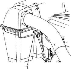
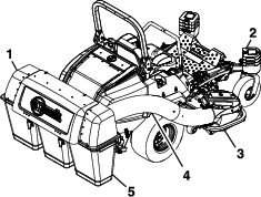
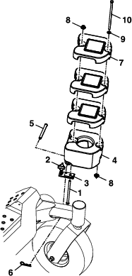
Check Blower Housing/Impeller
| Maintenance Service Interval | Maintenance Procedure |
|---|---|
| Before each use or daily |
|
-
Stop engine, wait for all moving parts to stop, and remove key. Engage parking brake.
-
Inspect for wear or damage daily. Replace or repair worn parts as needed.
Note: When mowing in areas with sandy soil, use low lift blades on the cutting deck and higher cutting heights to minimize wear on the blower components.
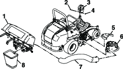
Check Bags
| Maintenance Service Interval | Maintenance Procedure |
|---|---|
| Before each use or daily |
|
-
Stop engine, wait for all moving parts to stop, and remove key. Engage parking brake.
-
Inspect the bags for wear, tears, or damage.
Warning
Under normal use the bag will deteriorate and wear. Objects could exit through worn bag at high speeds. Thrown objects can cause serious injury or kill you or bystanders.
Check bags frequently for tears and holes. Replace worn bags only with Exmark replacement bags.
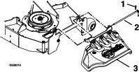
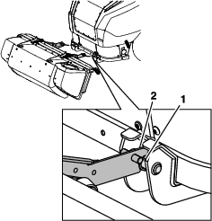
Lubricate Grease Fittings
| Maintenance Service Interval | Maintenance Procedure |
|---|---|
| Every 25 hours |
|
Note: See chart for service intervals.
-
Stop engine, wait for all moving parts to stop, and remove key. Engage parking brake.
-
Lubricate fittings with NLGI grade #2 multi-purpose gun grease.
Refer to the following chart for fitting locations and lubrication schedule.
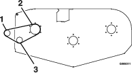
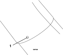
Lubrication Chart Fitting Locations Initial Pumps Number of Places Service Interval 1. Idler Bushings 1–2 1 25 Hours
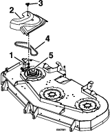
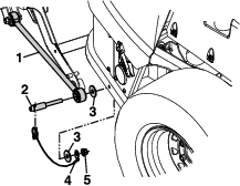
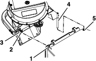
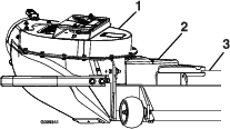
Check Condition of Belt
| Maintenance Service Interval | Maintenance Procedure |
|---|---|
| Every 50 hours |
|
-
Stop engine, wait for all moving parts to stop, and remove key. Engage parking brake.
-
Inspect the belt for damage or wear. Replace belt with one of the following:
Deck Part No. 60 inch 103-0866 72 inch 103-0867
Cleaning
Cleaning and Storing Safety
-
Park machine on level ground, disengage drives, set parking brake, stop engine, and remove key. Wait for all moving parts to stop before leaving the operator’s position. Allow the machine to cool before servicing, adjusting, fueling, unclogging, cleaning, or storing.
-
Clean grass and debris from the cutting unit, muffler, drives, grass catcher, and engine compartment to prevent fires.
-
Allow the machine to cool before storing the machine in any enclosure. Do Not store the machine or fuel container, or refuel, where there is an open flame, spark, or pilot light such as on a water heater or other appliance.
Clean Muffler and Rear Frame Area
| Maintenance Service Interval | Maintenance Procedure |
|---|---|
| Before each use or daily |
|
Stop engine, wait for all moving parts to stop, and remove key. Engage parking brake.
Warning
Operating engine parts, especially the muffler, become extremely hot. Severe burns can occur on contact and debris, such as leaves, grass, brush, etc. can catch fire.
-
Allow engine parts, especially the muffler, to cool before touching.
-
Remove accumulated debris from muffler and engine area.
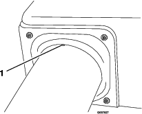
Clean Hood Screen on Mower
| Maintenance Service Interval | Maintenance Procedure |
|---|---|
| Before each use or daily |
|
-
Stop engine, wait for all moving parts to stop, and remove key. Engage parking brake.
-
Clean off any debris or grass build-up from the mower hood screen.
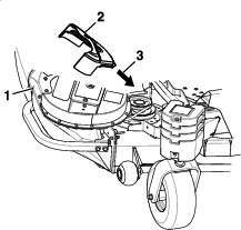
Clean Rear Screen In Hood Assembly
| Maintenance Service Interval | Maintenance Procedure |
|---|---|
| Before each use or daily |
|
-
Stop engine, wait for all moving parts to stop, and remove key. Engage parking brake.
-
Open hood and remove clippings that are stuck to the screen.
Clean Blower
| Maintenance Service Interval | Maintenance Procedure |
|---|---|
| Yearly or before storage |
|
Grass build up may cause problems with the impeller when the unit is put back into operation.
-
Stop engine, wait for all moving parts to stop, and remove key. Engage parking brake.
-
Remove grass buildup from around the impeller before placing it in storage.