Introduction
The AutoSteer kit is an accessory for the GeoLink™ spray system, used for a turf spray application vehicle, and is intended to be used by professional, hired operators in commercial applications. It is designed primarily for spraying on well-maintained lawns in parks, golf courses, sports fields, and on commercial grounds. Using this product for purposes other than its intended use could prove dangerous to you and bystanders.
Visit www.Toro.com for product safety and operation training materials, accessory information, help finding a dealer, or to register your product.
Installation
Preparing the Machine
Caution
Chemicals are hazardous and can cause personal injury.
-
Read the directions on the chemical labels before handling the chemicals and follow all manufacturer recommendations and precautions.
-
Keep chemicals away from your skin. Should contact occur, wash the affected area thoroughly with soap and clean water.
-
Wear goggles and any other protective equipment recommended by the chemical manufacturer.
-
Park the machine on a level surface.
-
Engage the parking brake.
-
Ensure that the tires are aligned straight ahead.
-
Shut off the engine and remove the key.
-
Wait for all movement to stop before leaving the operator’s seat.
-
Clean the sprayer; refer to Cleaning the Sprayer in the Operator’s Manual for the machine.
-
Allow the machine components to cool.
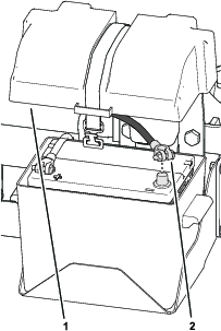
Remove the Negative Battery Cable
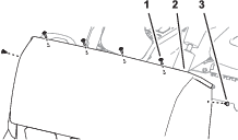
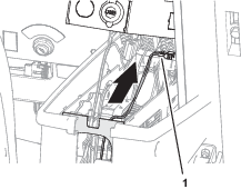
Removing the Hood
-
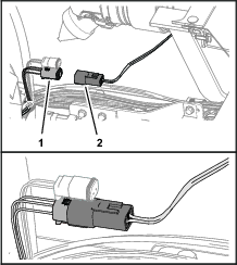
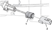
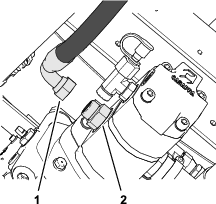
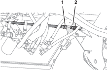
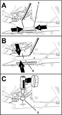
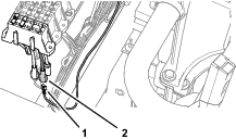
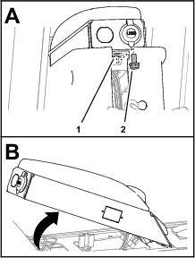
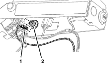
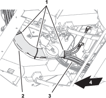
Remove the headlight connector of the machine wire harness from the connector of the headlight bulb (Figure 2).
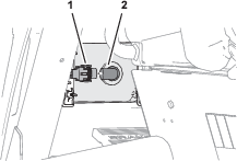
-
Repeat step 1 at the other headlight.
-
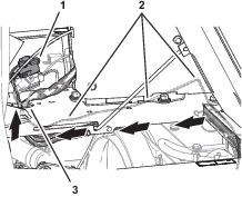
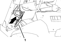
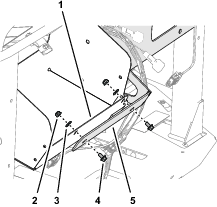
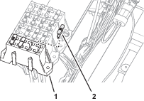
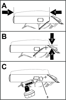
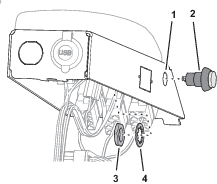
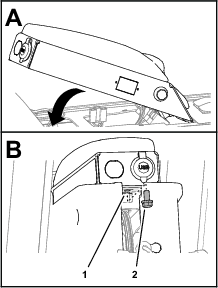
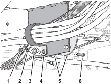
Remove the 4 push-in fasteners that secure the bottom flange of the hood to the machine (Figure 3).
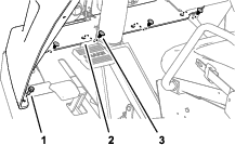
-
Remove the 2 flange-head bolts (5/16 x 3/4 inch) that secure the bottom flange to the machine (Figure 3).
-
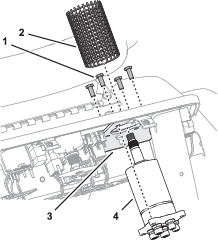
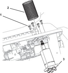
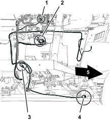
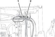
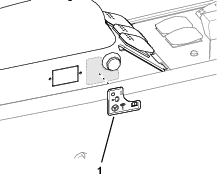
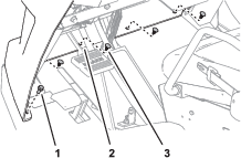
Remove the 4 Phillips pan-head screws (1/4 x 1 inch) that secures the hood to the dash support (Figure 4).
-
Remove the 2 push-in fasteners that secure the hood to the dash support (Figure 4).
-
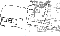
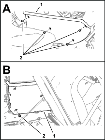
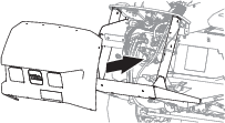
Remove the hood from the machine (Figure 5).
Note: Retain the hood, 2 flange-head bolts, and 4 Phillips pan-head screws.
Removing the Heat Shield and Undercarriage Shroud
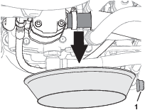
If equipped, remove the heat shield and shroud from the bottom of the machine; refer to the Operator’s Manual for your machine.
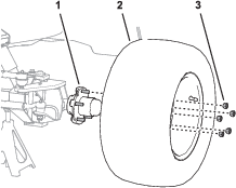
Removing the Left, Front Wheel
-
Lift the machine and support it with jack stands; refer to the Operator’s Manual for your machine.
-
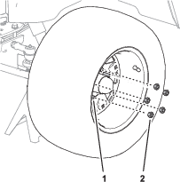
Remove the 5 wheel nuts that secure the left tire and wheel to the wheel hub, and remove the wheel from the machine (Figure 6).
Replacing the Left Spindle
Parts needed for this procedure:
| Left spindle | 1 |
| Bushing | 2 |
| Grease fitting | 1 |
| King pin | 1 |
| Cotter pin (1-1/4 x 1/8 inches—from kit Model 41636) | 2 |
| Cotter pin (1-1/2 x 5/32 inch—from kit Model 41636) | 1 |
| Shim | 1 |
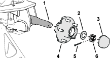
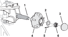
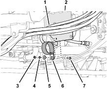
Removing the Wheel Hub
-
Remove the dust cap from the hub.
-
Remove the cotter pin that secures the slotted nut to the spindle, and remove the slotted nut and thrust washer (.
Note: Discard the cotter pin.
-
Carefully remove the hub from the spindle.
Removing the Spindle
-
Remove the cotter pin that secures the slotted nut to the tie-rod end of the steering cylinder, and remove the slotted nut and thrust washer.
Note: Discard the cotter pin.
-
Separate the tie rod end of the cylinder from the steering arm of the left spindle.
-
Remove the cotter pin that secures the slotted nut to the tie-rod end of the steering rod, and remove the slotted nut.
Note: Discard the cotter pin.
-
Separate the tie rod end of the steering rod from the tie-rod arm of the left spindle.
-
Remove the flange head bolt (5/16 x 5/8 inch) and washer (3/8 x 7/8 inch) the secure the king pin to the yoke of the front axle.
Note: Retain the flange head bolt and washer for installation of the new spindle. Discard the old king pin.
-
Remove the king pin from the yoke and left spindle, and remove the spindle from the yoke.
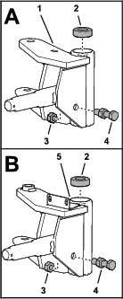
Preparing the New Spindle
-
Insert the 2 bushings into the ends of the king pin sleeve of the spindle.
Note: Ensure that the bushings are fully seated in the spindle.
-
Assemble the grease fitting into the hole in the king-pin sleeve.
-
Remove the thrust bushing from the top of the old left spindle.
-
Remove the nut (1/2 inch) that secures the axle stop bolt to the spindle.
Important: Do not move the other nut assembled at the middle of the stop bolt.
Note: You no longer need the old left spindle.
-
Assemble the axle stop bolt and nut into the hole in the new left spindle.
-
Secure the stop bolt to the spindle with the previously removed nut.
-
Assemble the thrust bearing into the top of the new left spindle.
Installing the Spindle to the Machine
-
Align the holes in the thrust bushing and the spindle with the hole in the yoke of the axle.
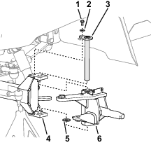
-
Assemble the spindle to the yoke with the new king pin.
-
Install the shim into the wheel humb/spindle assembly.
-
Secure the king pin to the yoke with the previously removed flange head bolt (5/16 x 5/8 inch) and washer (3/8 x 7/8 inch).
-
Grease the spindle at the grease fitting at the king-pin sleeve; refer to Preparing the New Spindle; refer to the Operator’s Manual for the specified grease.
Assembling the Steering Rod and the Steering Cylinder to the Spindle
-
Assemble the tie-rod end of the steering rod into the hole in the tie-rod arm of the left spindle.
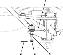
-
Assemble the slotted nut (1/2 inch) onto the tie-rod end and torque the nut to 27 to 34 N∙m (20 to 25 ft-lb).
Note: If the slot of the nut and the hole in the rod end do not align, tighten nut until the next slot aligns with the hole.
-
Secure the slotted nut to the tie-rod end with the cotter pin (1-1/4 x 1/8 inches).
Note: Bend both ends of the cotter pin.
-
Assemble the tie-rod end of the steering cylinder into the hole in the steering arm of the left spindle.
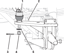
-
Assemble the slotted nut (12 mm) and thrust washer (1/2 x 1-1/8 inches) onto the tie-rod end, and torque the nut to 27 to 34 N∙m (20 to 25 ft-lb).
Note: If the slot of the nut and the hole in the rod end do not align, tighten nut until the next slot aligns with the hole.
-
Secure the slotted nut to the tie-rod end with the cotter pin (1-1/4 x 1/8 inches).
Note: Bend both ends of the cotter pin.
Installing the Wheel Hub
-
Align the hub the spindle, and carefully slide the hub onto the spindle.
-
Assemble the thrust washer and the slotted nut (1 inch) onto the spindle.
-
Tighten the slotted nut to 9 to 180 N∙m (75 to 180 in-lb).
-
Loosen the slotted nut until it moves away from washer and hub has end play.
-
Tighten the slotted nut to 170 to 226 N∙cm (15 to 20 in-lb).
Note: If the slot of the nut and the hole in the spindle do not align, tighten nut until the next slot aligns with the hole.
-
Secure the slotted nut to the tie-rod end with the cotter pin.
Note: Bend both ends of the cotter pin.
Installing the Steering Position Sensor
Parts needed for this procedure:
| Steering position sensor (magnetic target and sensor) | 1 |
| Jam nut (10 mm) | 1 |
| Sensor bracket | 1 |
| Sensor alignment tool | 1 |
| Pan-head screw (#4 x 3/4 inch) | 2 |
| Locknut (#4) | 2 |
| Flange-head capscrew (1/4 x 3/4 inch) | 2 |
| Locknut (1/4 inch) | 2 |
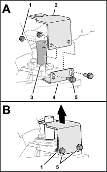
Installing the Sensor Bracket
-
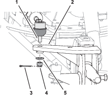
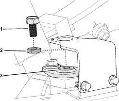
Remove the capscrew from the end of the kingpin (Figure 17).
Note: Discard the capscrew.
-
Thread the alignment tool into the top of the king pin (Figure 17).
-
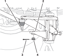
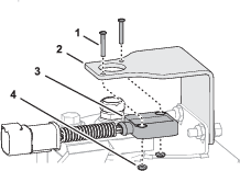
Align the sensor bracket over the alignment tool and the slots in the flange of the spindle (Figure 18).
-
Loosely assemble the bracket to the flange (Figure 18) with 2 flange-head capscrews (1/4 x 3/4 inch) and 2 locknuts (1/4 inch).
-
Position the bracket to the bottom of the slots in the flange of the spindle, and tighten the flange-head capscrews and locknuts (Figure 18).
-
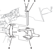
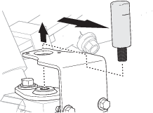
Remove the alignment tool (Figure 19).
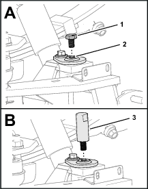
Assembling the Magnetic Target and Sensor
-
Fully thread the jam nut onto the magnetic target.
-
Thread the magnetic target into the top of the king pin.
-
Assemble the steering position sensor to the sensor bracket with 2 pan-head screws (#4 x 3/4 inch) and locknuts (#4), and tighten the screws and locknuts.
Adjusting the Magnetic Target
-
Adjust the position of the magnetic target until you measure a gap 4 mm (0.16 inch) between the target and the face of sensor (Figure 22).
-
Rotate the magnetic target until the indicator line that is stamped into the flat of the magnetic target aligns with the wiring port of the sensor (Figure 22).
-
Tighten the jam nut (Figure 22).
-
Measure the gap between the target and the face of sensor (Figure 22). You should measure 2 to 4 mm (0.08 to 0.16 inch).
Note: If the gap is smaller than 2 mm (0.08 inch) or larger than 4 mm (0.16 inch)—adjust the position of the magnetic target, align the indicator line, and tighten the jam nut.
Installing the Wheel
Routing the ISO-CAN Bus Harness
Parts needed for this procedure:
| ISO-CAN bus harness—302 cm (119 inches) | 1 |
| Cable ties | 12 |
Identifying the GeoLink Navigation Cable Type
-
Look at the type of cover over the navigation cable of your GeoLink system.
-
Record the type of navigation cable cover here:
Removing the Terminating Resistor Harness
-
Tilt the passenger seat forward and secure it with the prop rod.
-
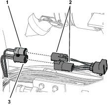
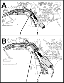
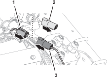
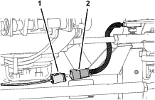
Remove the 2-pin and 4-pin connectors of the terminating-resistor harness from the 2-socket connector (switched power) and 4-socket connector (labeled CAN 1/ISOBUS) of the GeoLink harness (Figure 25).
Connecting the ISO-CAN Bus Harness to the GeoLink Harness
Routing the Harness to the Console Base
-
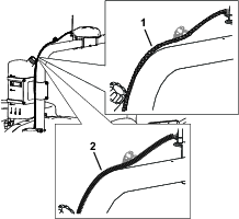
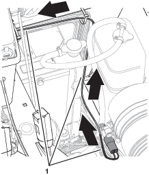
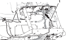
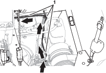
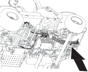
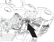
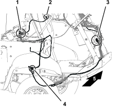
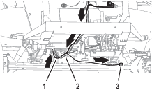
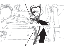
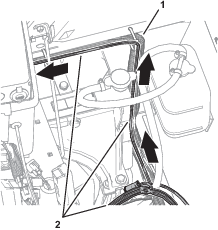
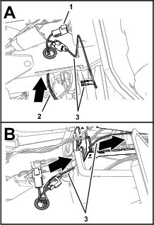
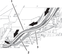
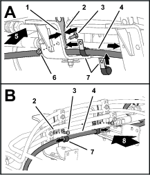
At the right side of the radiator, rout the ISO-CAN bus harness up, along the machine wire harness, and toward the center console (Figure 28).
-
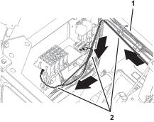
Route the ISO-CAN bus harness under the console base and along the machine wire harness (Figure 29).
-
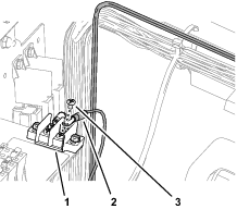
Route the 3-pin connector (labeled TO TORO CANBUS) and 3-socket connector (labeled CAN PORT A) of the ISO-CAN bus harness through the hole in the console base (Figure 29).
-
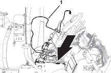
Bundle the ISO-CAN bus harness as shown in Figure 30.
-
Secure the ISO-CAN bus harness to the machine wire harness with 6 cable ties.
Connecting the ISO-CAN Bus Harness to the GeoLink Harness
-
At the front of the machine, align the 4-pin connector of the ISO-CAN bus harness—302 cm (119 inches) labeled TO ISOBUS toward the dash panel (Figure 31).
-
Remove the ISO bus terminator from the 4-socket connector of the GeoLink harness labeled CAN 1 ISOBUS TERMINATOR (Figure 32).
Note: You no longer need the cap.
-
Plug the TO ISOBUS connector of the ISO-CAN bus harness into the CAN 1 ISOBUS TERMINATOR connector of the GeoLink harness (Figure 32).
Routing the Harness to the Console Base
-
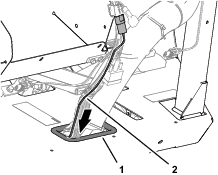
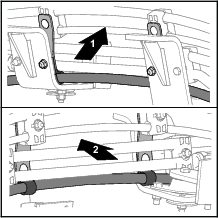
Route the other end of the ISO-CAN bus harness through the grommet of the floor (Figure 33).
-
Secure the ISO-CAN bus harness to the machine wire harness with 2 cable ties.
-
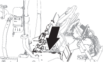
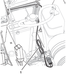
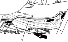
At the bottom of the machine, route the ISO-CAN bus harness along the wire harness of the machine (Figure 34).
-
Secure the ISO-CAN bus harness to the machine wire harness with 3 cable ties.
-
Rotate the passenger seat forward and support it with the prop rod.
-
At the right side of the radiator, rout the ISO-CAN bus harness up, along the machine wire harness, and toward the center console (Figure 35).
-
Route the ISO-CAN bus harness under the console base and along the machine wire harness (Figure 36).
-
Route the 3-pin connector (labeled TO TORO CANBUS) and 3-socket connector (labeled CAN PORT A) of the ISO-CAN bus harness through the hole in the console base (Figure 36).
-
Secure the ISO-CAN bus harness to the machine wire harness with 6 cable ties.
Connecting the ISO-CAN Bus Harness to the Machine Wire Harness
-
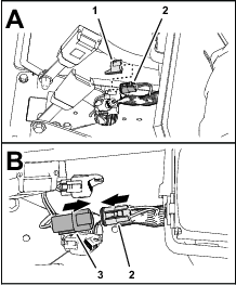
Remove the cap from the 3-socket connector of the machine wire harness (labeled CAN DIAGNOSTICS INTERCONNECT), as shown in Figure 37.
-
Plug the 3-pin connector of the ISO-CAN bus harness (labeled TO TORO CANBUS) into the 3-socket connector of the machine wire harness (labeled CAN DIAGNOSTICS INTERCONNECT), as shown in Figure 37.
Removing the CAN Bus Resistor
Removing the Console Side Panel
Removing the Terminating Resistor
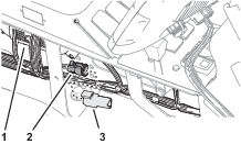
Forward of the TEC Controller, remove the resistor 75Ω from the 3-socket connector (not labeled) of the machine wire harness (Figure 39).
Note: Retain the resistor for installation in Installing the Adapter Harness and Terminating Resistor.
Note: You will install the side panel to the center console when you install the AutoSteer Kit for the Multi Pro 5800 Turf Sprayer with GeoLink; refer to the setup instructions in the AutoSteer kit Installation Instructions.
Installing the Adapter Harness and Terminating Resistor
Parts needed for this procedure:
| Adapter harness—13 cm (5 inches) | 1 |
| Cable tie | 1 |
-
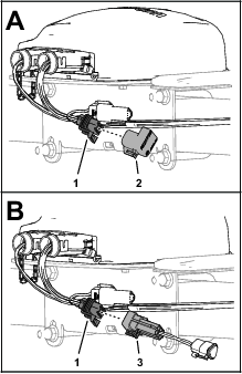
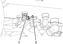
At the satellite receiver, remove the ISO bus terminator for the 6-socket connector of the GeoLink harness (Figure 40).
Note: You no longer need the ISO bus terminator.
-
Plug the 6-pin connector of the adapter harness—13 cm (5 inches) into the 6-socket connector of the GeoLink harness (Figure 40).
-
Plug the resistor that you removed in Removing the Terminating Resistor into the 3-socket connector of the adapter harness (Figure 41).
-
Secure the adapter harness to the GeoLink harness with a cable tie.
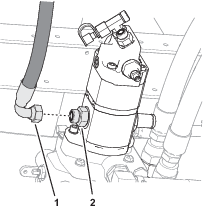
Plugging the Hydraulic Pump Suction Hose
Parts needed for this procedure:
| Hose plug (plastic) | 1 |
Important: When you remove the suction hose from the hydraulic pump, you must quickly install the hose plug to minimize hydraulic fluid loss.
-
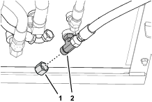
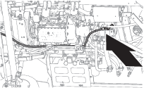
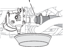
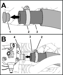
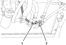
At the bottom of the machine, align a drain pan under the hydraulic pump and place the hose plug near the pump (Figure 42).
-
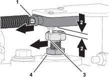
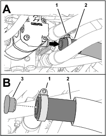
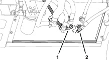
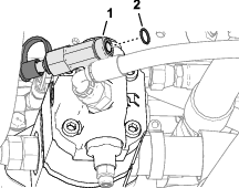
Loosen the hose clamp that secures the suction hose to the hydraulic pump (Figure 43).
-
Remove the suction hose from the barb fitting of the pump and insert the hose plug into the hose (Figure 43).
-
Secure the plug to the hose with the hose clamp.
Removing the Steering Wheel and Steering Valve
Removing the Steering Wheel
-
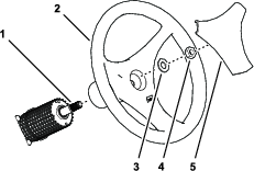
Remove the cover from the steering wheel (Figure 44).
-
Remove the nut (5/8 inch) and washer (5/8 inch) securing the steering wheel to the shaft of the steering valve (Figure 44).
-
Remove the steering wheel from the steering-valve shaft (Figure 44).
Note: Retain the nut, washer, steering wheel, and cover.
Removing the Valve
-
Remove the 2 capscrews and 2 locknuts that secure the hose guide to the flange of the storage compartment, and remove the guide (Figure 45).
Note: Discard the capscrews, locknuts, and hose guide.
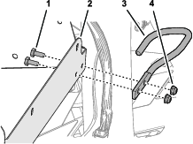
-
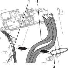
Remove the cable ties that secure the upper and lower covers to the steering hoses, and remove the covers (Figure 46).
Note: Retain the lower hose cover.
-
Disconnect the 5 steering hoses from the fitting of the steering valve (Figure 47).
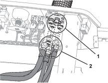
-
Remove the cable tie that secures the steering hoses to the wire harness of the machine (Figure 48).
-
Remove the cover from the steering valve (Figure 49).
-
Remove the 4 capscrews (8 x 20 mm) that secure the steering valve to the steering plate, and remove the valve from the plate (Figure 49).
Note: You no longer need the old steering valve; retain the steering-cover sleeve and 4 capscrews.
Installing the Steering Valve
Parts needed for this procedure:
| Steering valve | 1 |
Assembling the Steering Valve
-
Insert the shaft of the new steering valve through the steering plate (Figure 50).
-
Align the fitting for port R to the 3 o’clock position (Figure 51).
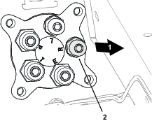
-
Secure the valve to the plate (Figure 50) with the 4 capscrew (8 x 20 mm) that you removed in Removing the Valve.
-
Assemble the steering-cover sleeve over the steering valve (Figure 50).
Installing the Steering Wheel
-
Ensure that the front tires are aligned forward.
-
Apply a light coat of anti-seize compound to the steering valve shaft.
-
Align the large spoke of steering wheel down, and assemble it over the shaft of the steering valve (Figure 52).
-
Assemble the washer (5/8 inch) and nut (5/8 inch) onto the shaft (Figure 52).
-
Torque the nut to 27 to 35 N∙m (20 to 26 ft-lb).
-
Assemble the cover onto the steering wheel (Figure 52).
Removing the Steering Valve Hoses
Parts needed for this procedure:
| Cap | 1 |
Removing the Hose Support Clamps
-
Under the floor plate, remove the nut (1/4 inch), lock washer (1/4 inch), washer (3/8 x 7/8 inch), and capscrew (1/4 x 7/8 inch) that secure the clamp supporting the hydraulic hoses to the clutch plate, and remove the clamp (Figure 53).
-
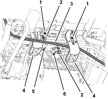
At the right side of the machine, remove the flange locknuts (5/16 inch), carriage bolt (5/16 x 1 inch), and carriage bolt (5/16 x 1-1/2 inches) that secure the 2 clamps supporting the return hose of the steering valve to the engine mounts, and remove the clamps (Figure 54).
-
Remove the 2 flange locknuts (5/16) securing the 2 upper tube-clamp halves as shown in Figure 55, and remove the clamp halves.
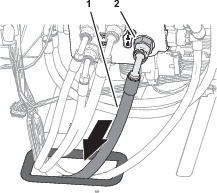
Removing the Return Hose for the Steering Valve
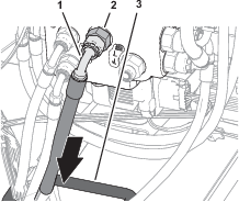
Removing the Pressure Hose for the Steering Valve
-
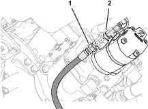
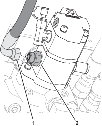
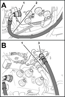
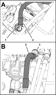
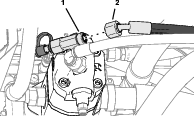
Disconnect the pressure hose for the steering valve from the T-fitting at the end of the hydraulic pump.
-
Remove the pressure hose from the machine.
Note: Discard the pressure hose.

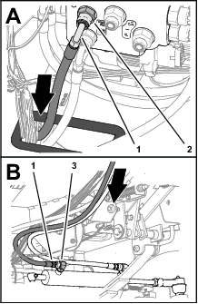
Removing the Forward Pressure Hose for the Boom-Lift Manifold
-
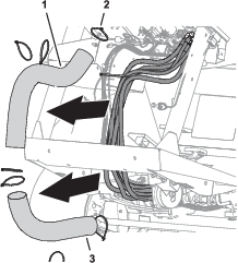
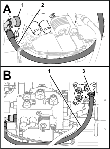
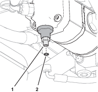
Disconnect the forward pressure hose for the boom-lift manifold from the straight fitting at the left side of the hydraulic pump (Figure 62).
-
Disconnect the forward-pressure hose for the boom-lift manifold from the bulkhead fitting at the back end of the hydraulic tank (Figure 64).
-
Remove the forward pressure hose from the machine (Figure 64).
Note: Discard the pressure hose.
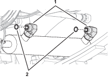
Removing the Steering Cylinder Hoses
-
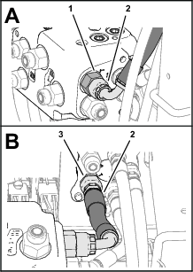
Disconnect the steering-cylinder hoses from the 90° fittings in the extend and retract ports of the steering cylinder (Figure 65).
-
Remove the steering-cylinder hoses from the machine.
Note: Discard the steering-cylinder hoses.
Installing the EHI Steering Valve
Parts needed for this procedure:
| Manifold mount | 1 |
| Flange-head capscrew (1/4 x 1/2 inch) | 2 |
| Washer (1/4 inch) | 2 |
| Flange locknut (1/4 inch) | 2 |
| U-bolt (3/8 inch) | 2 |
| Flange locknut (3/8 inch) | 4 |
| Model/serial decal | 1 |
| EHI steering valve | 1 |
| Straight hydraulic fitting (-6 x 12 mm) | 2 |
| Straight hydraulic fitting (-8 x 22 mm) | 4 |
| Straight hydraulic fitting (-6 x 18 mm) | 4 |
| Flange-head capscrew (8 x 16 mm) | 3 |
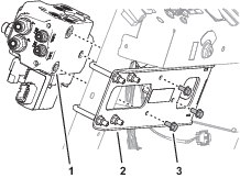
Installing the Manifold Mount
-
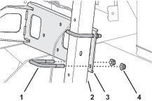
Align the manifold mount to the front of the machine as shown in Figure 66.
-
Align the holes in the manifold mount with the slots in the flange of the storage compartment (Figure 67).
Note: Ensure that the wires harness is not pinched between the mount and the compartment.
-
Loosely assemble the manifold mount to the flange (Figure 67) with 2 flange-head capscrews (1/4 x 1/2 inch), 2 washers (1/4 inch), and 2 flange locknuts (1/4 inch).
-
Loosely assemble the manifold mount to the dash support tube (Figure 68) with 2 U-bolts (3/8 inch) and 4 flange locknuts (3/8 inch).
-
Tighten the capscrews, U-bolts, and locknuts.
Affixing the Model/Serial Decal
-
Remove the backing from the model/serial decal.
-
Affix the decal to the manifold mount as shown in Figure 69.
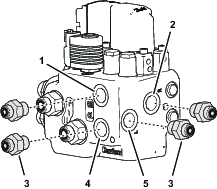
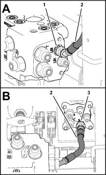
Preparing the EHI Steering Valve
-
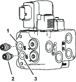
Assemble 2 straight hydraulic fittings (-6 x 12 mm) into the EHI steering valve (Figure 70) as follows:
-
Port LS1
-
Port LS2
-
-
Remove the 2 plugs from port P and port T of the EHI steering valve (Figure 71).
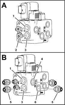
-
Assemble 4 straight hydraulic fittings (-6 x 22 mm) into the valve (Figure 71) as follows:
-
Port P
-
Port T
-
Port P (EF)
-
Port T (EF)
-
-
Assemble 4 straight hydraulic fittings (-6 x 18 mm) into the EHI steering valve (Figure 72) as follows:
-
Port CR
-
Port R
-
Port CL
-
Port L
-
Drilling the Console Base
Parts needed for this procedure:
| Grommet | 1 |
-
Tilt the passenger seat forward to access the console base (Figure 74).
-
Align a piece of sheet metal, approximately 120 mm (4 inches) wide, through the prop-rod slot in the console base, between the base and the wire harness below it.
Note: The sheet metal protects the wire harness when you drill through the console base.
-
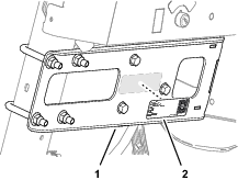
Measure 69 mm (2-11/16 inches) rearward from the square hole near the prop-rod slot in the console base, and mark the console base (Figure 75).
-
Measure 45 mm (1-3/46 inches) inward from the slotted flange of console base, and mark the console base (Figure 75).
-
Center punch the console base at the intersection of the marks.
-
Drill a hole in the console base at the centerpunch mark with a 32 mm (1-1/4 inches) drill bit (Figure 75).
-
Remove the sheet piece of sheet metal, and remove any burrs around the hole.
-
Install the grommet into the hole (Figure 76).
Installing the Electrical Harness
Parts needed for this procedure:
| 2-position switch | 1 |
| Transport decal | 1 |
| Wire harness | 1 |
| Cable tie | 7 |
| Fuse (10 A) | 1 |
| Push-button switch, jam nut, and lock washer | 1 |
| AutoSteer remote-engage decal | 1 |
Assembling the Road Switch to the Dash
-
Remove the plug in the dash panel as shown in Figure 77.

-
Align the 2-position switch with the shoulder of the switch (Figure 77) aligned to the top of the dash panel.
-
Insert the 2-position switch into the hole in the dash panel (Figure 77).
-
Apply the transport decal over the dash decal as shown in Figure 78.
Routing the Wire Harness at the Dash
-
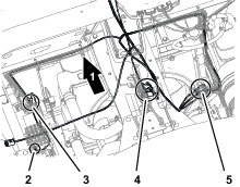
At the front of the machine, route the wire-harness connectors (Figure 82) with the following labels through the bottom of the floor plate:
-
Plug the 12-socket wire-harness connector labeled into the 12-pin connector of the EHI steering-valve (Figure 83).
-
Plug the 2-socket wire-harness connector labeled into the 2-pin connector of the EHI-solenoid (Figure 83).
-
Remove the cap from the 4-socket connector GeoLink wire harness labeled (Figure 84).
-
Plug the 4-pin connector of the kit wire harness labeled into the 4-socket connector labeled (Figure 84).
-
Plug the 8-socket connector of the kit wire harness labeled (Figure 85) into the 2-position switch that you installed in Assembling the Road Switch to the Dash.
Routing the Wire Harness Under the Operator’s Platform
-
Route the wire harness for the kit rearward, along the wire harness for the machine (Figure 86).
-
Route the wire harness branch with the connector labeled along the back of the front axle tube (Figure 86).
-
At the bottom, back side of the radiator, route the wire harness up, along the machine wire harness (Figure 87).
Connecting the Wheel Angle Sensor
-
Plug the 6-pin connector of the angle-sensor harness into the 6-socket connector of the kit wire harness labeled (Figure 88).
-
Secure the harness of the wheel angle sensor and the angle-sensor branch of the kit wire harness to the axle tube with 2 cable ties.
Connecting the Wire Harness to the Ground Block and Fuse Block
-
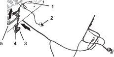
Route the wire harness branch with the terminals labeled and across the top of the radiator, along the machine wire harness (Figure 89).
-
Remove a terminal screw from the ground block (Figure 90).
-
Assemble the ring terminal of the kit wire harness labeled to the ground block with the terminal screw (Figure 90).
-
Plug the terminal of the kit wire harness labeled into the blade connector for options power of the fuse block (Figure 91).
Note: If the fuse block of your machine does not have an available options-power circuit, install an additional options-fuse block; refer to your authorized Toro distributor.
-
Insert the fuse (10 A) into the fuse-block socket (Figure 92) for the options power circuit that you used in step 4.
-
Secure the switched power and ground branch of the kit wire harness to the machine wire harness with 4 cable ties.
Connecting the Remote Engage Connectors
Plug the 2-pin connector of the kit wire harness labeled into the 2-socket connector of the GeoLink wire harness labeled (Figure 93).
Removing the Armrest
-
Remove 4 flange-head capscrews (1/4 x 3/4 inch) that secure the side panel of the center console as shown in Figure 94.
-
Tilt the seat forward, and remove the lower rear flange-head capscrew (Figure 94).
-
Repeat steps 1 and 2 at the other side of the center console.
-
Remove the flange-head capscrew (5/16 x 5/8 inch) that secures the arm panel to the console frame (Figure 95).
-
Lift the arm panel from the frame (Figure 95).
Drilling a Hole in the Armrest
-
Measure 260 mm (10-1/4 inches) from the back end of the arm panel, and mark the panel (Figure 96).
-
Measure 35 mm (1-3/8 inches) from the top of the arm panel, and mark the panel (Figure 96).
-
Center punch the intersection of the marks.
-
Protect the wire in the arm panel.
-
Drill a 17 mm (11/16 inch) hole in the arm panel at the centerpunch mark (Figure 96).
-
Remove any burrs from the hole.
Assembling the Push-Button Switch to the Armrest
Routing the Wire Harness to the Remote Engage Switch
-
Route the wire harness branch labeled REMOTE ENGAGE SWITCH through the grommet (Figure 98) that you installed in Drilling the Console Base.
-
Route the wire harness branch labeled REMOTE ENGAGE SWITCH) into the center console (Figure 98).
-
Route the wire harness branch labeled REMOTE ENGAGE SWITCH) toward the arm panel (Figure 99).
-
Assemble the terminals of the wire harness branch labeled REMOTE ENGAGE SWITCH) onto the terminals of the push-button switch (Figure 100).
-
Secure the wire harness branch to the machine wire harness with a cable tie.
Assembling the Arm Panel to the Console Frame
-
Align the tabs at the front of the arm panel with the slots in the console frame, and rotate the arm pane down (Figure 101).
-
Secure the arm panel to the console frame (Figure 101) with the flange-head capscrew (5/16 x 5/8 inch).
-
Assemble the side panel to the console frame (Figure 102) with 4 flange-head capscrews (1/4 x 3/4 inch).
-
Tilt the seat forward and install the lower rear flange-head capscrew (Figure 102).
-
Repeat steps 3 and 4 at the other side of the center console.
-
Affix the AutoSteer remote-engage decal to the arm panel as shown in Figure 103.
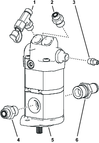
Replacing the Hydraulic Pump
Parts needed for this procedure:
| O-ring 1.6/1.8 mm (0.489 /0.070 inch) | 2 |
| O-ring 15.6/1.8 mm (0.614/0.070 inch) | 1 |
| O-ring 29.7/2.9 mm (1.171/0.116 inch) | 1 |
| O-ring 16.4/2.3 mm (0.644/0.090 inch) | 1 |
| Hydraulic pump | 1 |
| Straight fitting (7/8 x 13/16 inch) | 1 |
| Straight fitting (1/4 x 1/4 inch) | 1 |
| O-ring 85.7/ mm (3.375/0.630 inch) | 1 |
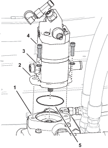
Removing the Hydraulic Pump
-
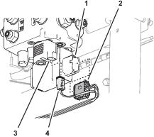
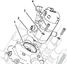
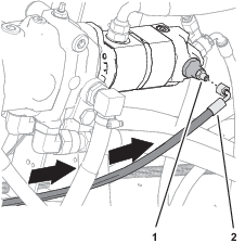
Disconnect the pressure hose for the spray-pump motor from the straight fitting in the left side of the hydraulic pump (Figure 104).
-
Remove the 2 socket-head screws (3/8 x 1 inch) and 2 washers (3/8 inch) that secure the hydraulic pump to the traction pump, and remove the hydraulic pump (Figure 105).
Removing the Hydraulic Fittings from the Pump
Replacing the Hydraulic Fitting O-rings
-
Working with the 3 hydraulic fittings that you removed in Removing the Hydraulic Fittings from the Pump, remove the 5 O-rings shown in Figure 107.
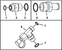
-
Install a new O-ring 7.6/1.8 mm (0.301/0.070 inch) and O-ring 15.6/1.8 mm (0.614/0.070 inch) into the grooves of the straight fitting (5/8 x 3/4 inch) as shown in Figure 107.
-
Install a new O-ring 29.7/2.9 mm (1.171/0.116 inch) into the groove of the barb fitting (Figure 107).
-
Install a new O-ring 7.6/1.8 mm (0.301/0.070 inch) and O-ring 16.4/2.3 mm (0.644/0.090 inch) into the grooves of the T-fitting (Figure 107).
Preparing the Hydraulic Pump
-
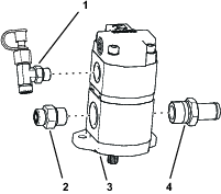
Install the T-fitting, test fitting, and cap that you removed in step 2 of Removing the Hydraulic Fittings from the Pumpinto the top, right port of the new hydraulic pump (Figure 108).
-
Install the straight fitting (7/8 x 13/16 inch) into the top, left port of the hydraulic pump (Figure 108).
-
Torque the straight fitting to 134 to 164 N∙m (99 to 121 ft-lb).
-
Install the straight fitting (1/4 x 1/4 inch) into the port fitting of the hydraulic pump, as shown in Figure 108.
-
Install the straight fitting (5/8 x 3/4 inch) into the body of the hydraulic pump, as shown in Figure 108.
-
Torque the straight fitting to 110 to 134 N∙m (81 to 99 ft-lb).
-
Install the barb fitting into the body of the hydraulic pump (Figure 108).
-
Torque the barb fitting to 164 to 202 N∙m (121 to 149 ft-lb).
Installing the Hydraulic Pump
-
Assemble an O-ring 85.7/ mm (3.375/0.630 inch) over the onto the front cover of the hydraulic pump (Figure 109).
-
Align the drive-shaft splines of the hydraulic pump with the coupling splines of the traction pump, and insert the drive shaft into the coupling (Figure 109).
-
Assemble the hydraulic pump to the traction pump with the 2 socket-head screws (3/8 x 1 inch) and 2 washers (3/8 inch) that you removed in Removing the Hydraulic Pump.
-
Torque the socket-head screws to 37 to 42 N∙m (27 to 31 ft-lb).
-
Assemble the pressure hose for the spray-pump motor to the straight fitting, and tighten the hose fitting (Figure 110).
Assembling the Suction Hose to the Pump
Installing the Forward Pressure Hose for the Boom-Lift Manifold
Parts needed for this procedure:
| Forward pressure hose 10 x 660 mm (3/8 x 26 inches) | 1 |
-
Loosely assemble the straight fitting of the forward pressure hose to the bulkhead fitting.
-
Route the hose to the hydraulic pump .
-
Assemble the 45° fitting of the forward pressure hose to the T-fitting of the hydraulic pump.
-
Tighten the hose fittings.
Installing the Hoses
Parts needed for this procedure:
| Hose 6 x 203 mm (1/4 x 8 inches); -6 (straight) and -6 (45°) fittings | 1 |
| O-ring 12.4/1.8 mm (0.489/0.070 inch) | 2 |
| Hose 6 x 2819 mm (1/4 x 111 inches); -4 (90°) and -6 (90°) fittings | 1 |
| Hose 6 x 673 mm (1/4 x 26-1/2 inches); -4 (straight) and -6 (90°) fittings | 1 |
| Hose 6 x 711 mm (1/4 x 28 inches); -4 (straight) and -6 (90°) fittings | 1 |
| Hose 10 x 187 mm (3/8 x 7-3/8 inches); -6 (straight) and -8 (90°) fittings | 1 |
| Hose 10 x 264 mm (3/8 x 10-3/8 inches); -8 (90°) and -6 (45°) fittings | 1 |
| O-ring 9.2/1.8 mm (0.364/0.070 inch) | 2 |
| Hose 6 x 1397 mm (1/4 x 55 inches); -6 (straight) and -6 (90°) fittings | 1 |
| Hose 6 x 1270 mm (1/4 x 50 inches); -6 (straight) and -6 (90°) fittings | 1 |
| Hose 10 x 2921 mm (3/8 x 115 inches); -8 (90°) and -8 (90°) fittings | 1 |
| O-ring 7.6/1.8 mm (0.301/0.070 inch) | 1 |
| Cable tie | 3 |
Installing the Steering Valve Hoses
-
Assemble the 45° fitting of the hose 6 x 203 mm (1/4 x 8 inches) onto the port LS2 fitting of the EHI steering valve (Figure 114).
-
Assemble the straight fitting of the hose 6 x 203 mm (1/4 x 8 inches) onto the port E fitting of the steering valve, and tighten both hose fittings (Figure 114).
-
Route the end of the hydraulic pump hose 6 x 2819 mm (1/4 x 111 inches) with the -4, 90° fitting through the grommet in the floor plate (Figure 115).
-
Assemble the -6, 90° fitting of the hose 6 x 2819 mm (1/4 x 111 inches) onto the port the LS1 fitting of the EHI steering valve, and tighten the hose fitting (Figure 115).
-
Assemble the 90° fitting of the hose 6 x 673 mm (1/4 x 26-1/2 inches) into the port R fitting of the EHI steering valve (Figure 116).
-
Assemble the straight fitting of the hose 6 x 673 mm (1/4 x 26-1/2 inches) into the port R fitting of the steering valve, and tighten both hose fittings (Figure 116).
-
Assemble the 90° fitting of the hose 6 x 711 mm (1/4 x 28 inches) onto the port L fitting of the EHI steering valve (Figure 117).
-
Assemble the straight fitting of the hose 6 x 711 mm (1/4 x 28 inches) onto the port L fitting of the steering valve, and tighten both hose fittings (Figure 117).
-
Assemble the 90° fitting of the hose 10 x 187 mm (3/8 x 7-3/8 inches) onto the port T fitting of the EHI steering valve (Figure 118).
-
Assemble the straight fitting of the hose 10 x 187 mm (3/8 x 7-3/8 inches) onto the port T fitting of the steering valve, and tighten both hose fittings (Figure 118).
-
Assemble the 90° fitting of the hose 10 x 264 mm (3/8 x 10-3/8 inches) onto the port P fitting of the EHI steering valve (Figure 119).
-
Assemble the 45° fitting of the hose 10 x 264 mm (3/8 x 10-3/8 inches) onto the port P fitting of the steering valve, and tighten both hose fittings (Figure 119).
Installing the Steering Cylinder Hoses
-
Route the end of the hose 6 x 1397 mm (1/4 x 55 inches) with the straight fitting through the grommet in the floor plate (Figure 120).

-
Assemble the 90° fitting of the hose 6 x 1397 mm (1/4 x 55 inches) onto the port CR fitting of the EHI steering valve (Figure 120).
-
Remove the 2 O-ring in the face 90° fittings in the extend and retract ports of the steering cylinder (Figure 121).
Note: Discard the O-ring.
-
Install a 2 new O-ring 9.2/1.8 mm (0.364/0.070 inch) into the groove of the 90° fittings (Figure 121).
-
Assemble the straight fitting of the hose 6 x 1397 mm (1/4 x 55 inches) onto the 90° fitting in the retract port of the steering cylinder, and tighten both hose fittings (Figure 120).
-
Route the end of the hose 6 x 1270 mm (1/4 x 50 inches) with the straight fitting through the grommet in the floor plate (Figure 122).
-
Assemble the 90° fitting of the hose 6 x 1270 mm (1/4 x 50 inches) onto the port CL fitting of the EHI steering valve (Figure 122).
-
Assemble the straight fitting of the hose 6 x 1270 mm (1/4 x 50 inches) onto the 90° fitting in the extend port of the steering cylinder, and tighten both hose fittings (Figure 122).
Assembling the Tank-Return Hose and Hydraulic-Pump Hose to the EHI Steering Valve
-
Identify the tank-return hose 10 x 2921 mm (3/8 x 115 inches) with 2 fittings (90°).
-
Route the end of the tank-return hose 10 x 2921 mm (3/8 x 115 inches) through the grommet in the floor plate (Figure 123).
-
Assemble the 90° fitting of the tank-return hose 10 x 2921 mm (3/8 x 115 inches) onto the port EF fitting of the EHI steering valve, and tighten the hose fitting (Figure 123).
-
Identify the hydraulic-pump hose 10 x 2921 mm (3/8 x 115 inches) with a 90° fitting and a 45° fitting.
-
Route the end of the hydraulic-pump hose 10 x 2921 mm (3/8 x 115 inches) with the 45° fitting the through the grommet in the floor plate (Figure 124).
-
Assemble the 90° fitting of the hydraulic-pump hose 10 x 2921 mm (3/8 x 115 inches) onto the port PT fitting of the EHI steering valve, and tighten the hose fitting (Figure 124).
-
Route the 2 hydraulic pump hoses and the tank-return hose rearward, along the right frame tube of the machine (Figure 125).
Routing the Hydraulic Pump Hoses
-
Route the hydraulic pump hose 10 x 2921 mm (3/8 x 115 inches—EHI steering valve port PT) with the 45° fitting into the top groove of the tube-clamp half at the upper location (Figure 126).
-
Route the 45° fitting of the hose toward the hydraulic pump.
-
Route the hydraulic pump hose 6 x 2819 mm (1/4 x 111 inches—EHI steering valve port LS1) with the 90° fitting into the bottom groove of the tube-clamp half at the upper location (Figure 127).
-
Route the 90° fitting of the hose toward the hydraulic pump.
-
Assemble the 2 tube-clamp halves onto the capscrews, and secure the tube-clamp halves and hoses (Figure 128) with 2 flange-head locknuts (5/16 inch).
Installing the Hydraulic Tank Return Hose
-
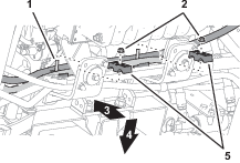
Route the tank-return hose 6 x 2819 mm (1/4 x 111 inches—EHI steering valve port EF) across the top of the right engine mount brackets (Figure 129).
-
Assemble the 2 P-clamps onto the hose as shown in Figure 129.
-
Align the 2 P-clamps between the tube clamp mount plates and the engine mount brackets (Figure 129).
-
Secure the clamp mount plates and P-clamps to the engine mount brackets (Figure 129 and Figure 130) with the 2 carriage bolt (5/16 x 1 inch) and 2 flange locknut (5/16 inch).
-
Remove the O-ring in the face of the T-fitting of the hydraulic tank (Figure 131).
Note: Discard the O-ring.
-
Install a new O-ring 12.4/1.8 mm (0.489/0.070 inch) into the groove of the T-fitting (Figure 131).
-
Assemble the 90° fitting of the tank-return hose 6 x 2819 mm (1/4 x 111 inches) onto the T-fitting, and tighten the hose fitting (Figure 132).
Installing the Hydraulic Pump Hoses
-
Remove the O-ring in the face of the T-fitting at the end the hydraulic pump (Figure 133).
Note: Discard the O-ring.
-
Install a new O-ring 12.4/1.8 mm (0.489/0.070 inch) into the groove of the T-fitting (Figure 133).
-
Assemble the 45° fitting of the hose 10 x 2921 mm (3/8 x 115 inches) onto the T-fitting, and tighten the hose fitting (Figure 134).
-
Remove the O-ring in the face of the straight fitting at the end of the hydraulic pump (Figure 135).
Note: Discard the O-ring.
-
Install a new O-ring 7.6/1.8 mm (0.301/0.070 inch) into the groove of the straight fitting (Figure 135).
-
Assemble the 90° fitting of the hose 6 x 2819 mm (1/4 x 111 inches) onto the straight fitting, and tighten the hose fitting (Figure 136).
Installing the Lower Hose Cover
-
Under the floor plate, secure the hoses and wire harnesses to the clutch and clutch plate as shown in Figure 137 with the support clamp, capscrew (1/4 x 7/8 inch), nut (1/4 inch), lock washer (1/4 inch), and washer (3/8 x 7/8 inch) that you removed in Removing the Hose Support Clamps.
-
Assemble the lower hose cover over the steering hoses (Figure 138).
-
Secure the cover to the hoses with 3 cable ties (Figure 138).
Installing the Negative Battery Cable
Purging Air from the Hydraulic System
-
Start the engine.
-
Fully turn the steering wheel left and right until the wheel turns smoothly.
-
Shut off the engine and remove the key.
Checking for Hydraulic Leaks
-
Check the hoses and fittings at the EHI steering valve and the steering valve for hydraulic leaks.
Important: Fix all leaks before installing the hood.
-
Check the hoses and fittings at the hydraulic tank and hydraulic pump for leaks.
Important: Fix all leaks.
Installing the Hood
Parts needed for this procedure:
| Push-in fasteners | 6 |
-
Align the holes in the hood with the holes in the chassis of the machine (Figure 140).
-
Assemble the hood to the dash support with 2 push-in fasteners (Figure 141).
-
Secure the hood to the dash support (Figure 141) with 4 Phillips pan-head screws (1/4 x 1 inch).
-
Assemble the bottom flange of the hood to the machine with 4 push-in fasteners (Figure 142).
-
Secure the flange to the machine (Figure 142) with 2 flange-head bolts (5/16 x 3/4 inch).
-
Assemble the headlight connector of the machine wire harness to the connector of the headlight bulb (Figure 143).
-
Repeat step 6 at the other headlight.
Installing the Heat Shield and Undercarriage Shroud
If removed, installed the heat shield and undercarriage shroud to the bottom of the machine; refer to the Operator’s Manual for your machine.
Checking the Hydraulic Fluid Level
Check the hydraulic fluid level. If the fluid level is low, add fluid to the hydraulic tank; refer to the Operator’s Manual for the hydraulic fluid specification and checking procedure.
Verifying the Software Version
-
Turn the ignition key to the RUN(gasoline) or PREHEAT/RUN (diesel) position.
-
Press the ABOUT (Toro) icon at the upper left corner of the control console (Figure 144).

-
When the software version is correct, the About dialog box displays software version 4.04 or higher.
Note: If the software versions differ, contact the Toro technical assistance center.
Verifying the Minimum Hardware Requirements
Ensure that your laptop computer that meets the hardware, operating system, and application requirements before installing the Danfoss PLUS+1® Service Tool; refer to the tables that follow.
|
Component |
Minimum Capacity |
|---|---|
|
CPU* |
1.5 GHz, 32–bit, 1 core, 2008 or later |
|
Memory |
1 GB |
|
Unused Hard Drive Space |
Greater than 1 GB |
|
Minimum Display Resolution |
1024 x 768 |
|
USB Port |
Version 2.0 or higher |
|
* The CPU must be intended for laptop use. Processors intended for netbooks, tablets, or similar devices are not recommended. |
|
|
Software |
Version |
|---|---|
|
Operating System Version |
Microsoft Windows 7—32 bit |
|
OS Components |
MSXML 4.0, Service Pack 2 (Microsoft XML Core Services) |
|
User Account Rights |
Local administrator access |
|
Software |
Notes |
|---|---|
|
Email Client/Reader |
For license registration. |
|
PDF Reader |
Any recent standards compliant reader. |
|
Web Browser |
Any recent standards compliant web browser (for HTML based F1 Help). |
Downloading the Software
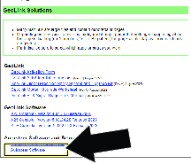
Downloading and Extracting the Software Files
-
Go to Gateway

-
Click on Service
-
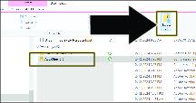
Note: The file saves to the Downloads directory of your laptop computer.
-
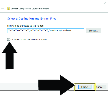
-
In the Extract Compressed dialog box, ensure that the check box is selected, and click the button .
Installing the Software and Driver Files
Installing the Software
Important: The person installing the PLUS+1 Service tool must have administrative privileges on the laptop computer.
-
Double click the PLUS+1 ServiceTool 12.0.7 setup.exe file.
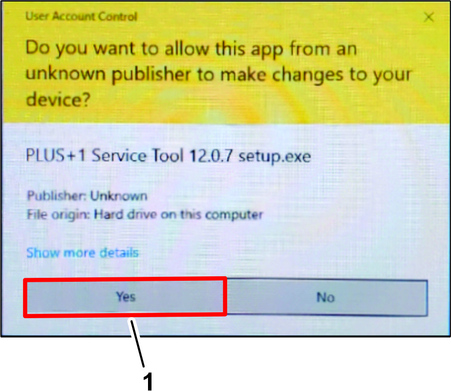
-
If the User Account Control dialog box displays, click the YES button (Figure 151).
-
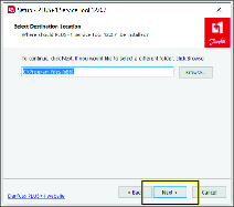
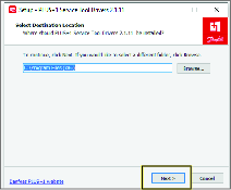
In the Select Destination Location dialog box, click the NEXT button.
-
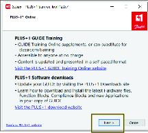
In the Plus+1 Online dialog box, click the NEXT button.
-
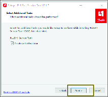
In the Select Additional Tasks dialog box, click the NEXT button.
-
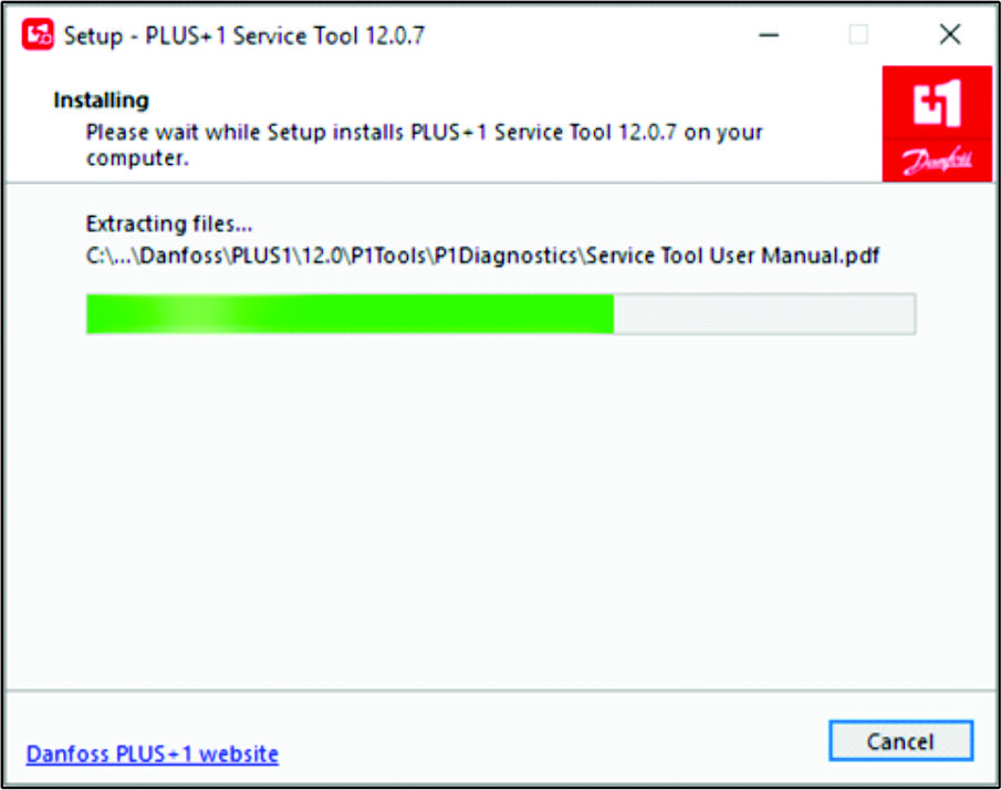
In the Ready to Install dialog box, click the INSTALL button.
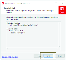
Note: The progress dialog box displays.
-
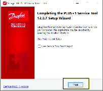
In the Completing Service Tool Setup Wizard dialog box, click the FINISHED button.
Installing the Drivers
-
In the Select Destination Location dialog box, click the NEXT button.
-
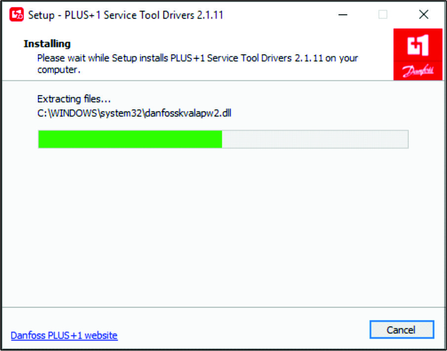
In the Ready to Install dialog box, click the INSTALL button.
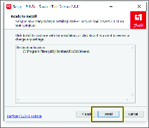
Note: The progress dialog box displays.
-
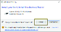
In the Would you like to install this device software dialog box, click the INSTALL button.
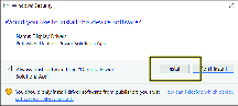
-
In the Would you like to install this device software dialog box, click the INSTALL button.
-
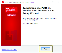
In the Completing Service Tool Drivers Setup Wizard dialog box, click the FINISHED button.
Installing the Service and Data Files
Opening the Program and Installing the Application
-
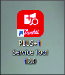
Double click on the Plus+1 Service Tool icon.
-
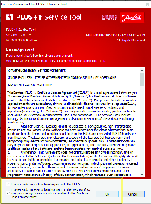
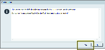
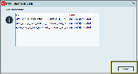
Read the license information, check the boxes noting you have read and agree to the agreement, and click OK.
-
Click OK on the confirmation screen.
-
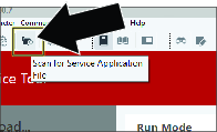
Click on the folder with magnifying glass icon to Scan for Service Application File.
-
Navigate to the Service tool folder in the PVED-CLS 2.00 firmware release package folder.
-
Click on PVED-CLS_2.00_rev_D and click OPEN.

-
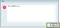
Click CLOSE if you receive this error. This is a passive error and will not effect the installation or use of this tool.
Installing the Diagnostic Data
-
Click the icon, and in the drop-down list, click the icon.

-
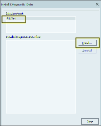
In the Install Diagnostic Data dialog box, click the PLUS+1 protocol icon, and press the icon.
-
Navigate to the Diagnostic data files folder in the PVED-CLS 2.00 firmware release package folder.
-
Select all the files in this folder and click OK.
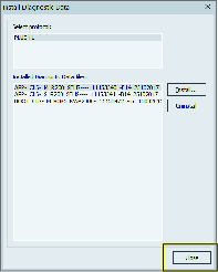
-
In the dialog box, click the icon.
-
In the dialog box, click the icon.
Selecting the Gateway Channel
-
Plug a Toro Diag cable into the USB port of the laptop computer and open the Plus+1 software program.
-
On the ribbon bar, click the Communication button.

-
In the Communication drop-down menu, click the Gateway button.
-
In the Gateway drop-down menu, click the Advanced button.
-
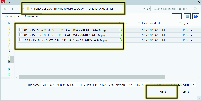
In the Advanced drop-down menu, click the Select Gateway... button.
-
On the Select Gateway Channel screen, click the Kvaser option in the Gateways list.
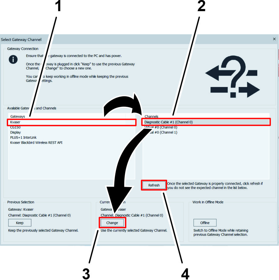
-
In the Channels menu, click the Diagnostic Cable option.
Note: If a diagnostic cable option does not display in the Channels menu, verify that the Toro Diag cable is plugged into the USB port of the laptop computer, click the Refresh button on the Select Gateway Channel screen, and click the Diagnostic Cable option.
-
Click the CHANGE button under the Current Selection heading.
Setting Up and Calibrating the Software
Calibrating the Compass
Ensure that the GeoLink compass is calibrated, refer to the GeoLink Software Guide for your machine.
Preparing to Calibrate the Machine
Installer provided equipment: a USB/CAN interface cable (Toro DIAG cable) Part No. 115-1944
-
Park the machine on the grass at a level location.
-
Shut off the engine and engage the parking brake.
Connecting the Laptop Computer to the Machine
-
If the Toro Diag application is running on the laptop computer, close the Toro Diag application.
Important: Do not begin the calibration process if the Toro Diag application is running on the laptop computer.
-
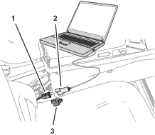
Plug the USB/CAN interface cable into a USB port of the laptop computer.
-
At the machine, rotate the key to the ON position.
-
Open the Plus+1 program.
-
Remove the cap from the 3-socket connector of the kit wire harness CAN port labeled DUPLICATE DIAG CONNECTOR, and plug the 3-pin connector USB/CAN interface cable into the 3-socket connector.
-
On the dash panel of the machine, press enable/transport switch to the ENABLE MODE position.
-
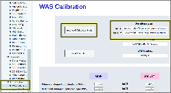
In the System Navigator tab, navigate to the AUTO CALIBRATION directory, expand the directory, and click on WAS Calibration.
-
Click GOTO WAS CALIBRATION MODE button.
Capturing Steering Values
-
Start the engine of the machine.
-
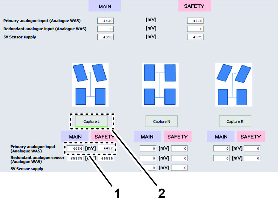
Fully turn the steering wheel to the left and stop.
-
Click the CAPTURE L button.
Note: The sensor value changes as you turn the steering wheel.
-
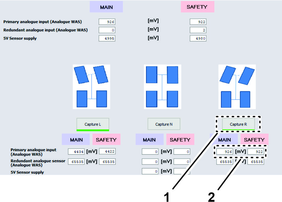
Fully turn the steering wheel to the right and stop.
-
Click the CAPTURE R button.
Note: The sensor value changes as you turn the steering wheel.
-
Turn the steering wheel until the tires align straight ahead and stop.
-
Click the CAPTURE N button.
Note: The sensor value changes as you turn the steering wheel.
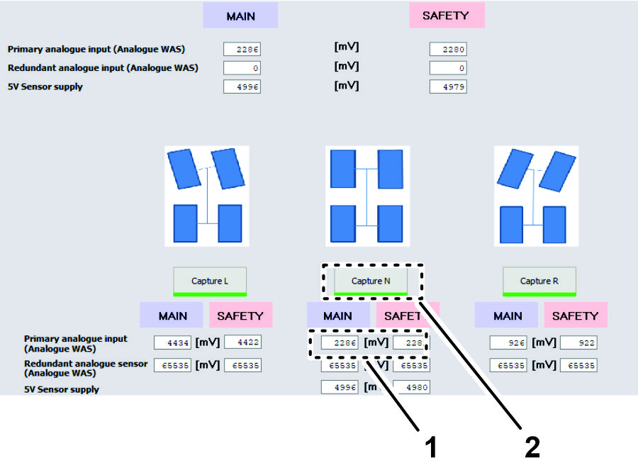
Verifying / Checking the WAS Calibration Values
-
Ensure that your values are within the minimum and maximum ranges as listed.

-
Click the ACCEPT AND SAVE button.
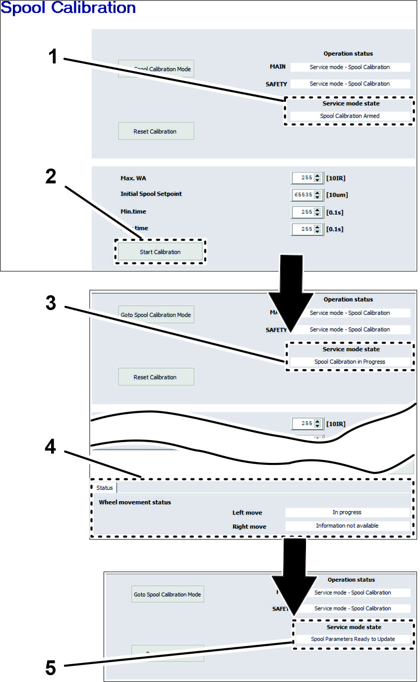
Running Spool Calibration Process
-
Turn the steering wheel as needed to position the front tires straight ahead.
-
In the System Navigator tab, navigate to the AUTO CALIBRATION directory, expand the directory, and click on SPOOL CALIBRATION.
-
On the spool calibration page, click the GOTO SPOOL CALIBRATION MODE button.
-
Click the START CALIBRATION button.
Note: The service mode state must display Spool Calibration Armed before starting calibration.
Important: Do not touch the steering wheel.
The steering wheel moves while spool calibrations proceeds. The spool calibration process takes several minutes. Note that the wheel movement status changes in Status tab. Calibration is finished when Service Mode State field displays SPOOL PARAMETERS READY TO UPDATE.
-
At the bottom of the spool calibration screen, click the ACCEPT AND SAVE icon (Figure 185).
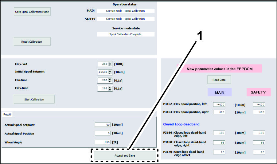
-
Shut off the engine.
-
Remove the connector of the USB/CAN interface cable from the connector of the kit wire harness, and install the cap onto the wire harness connector.
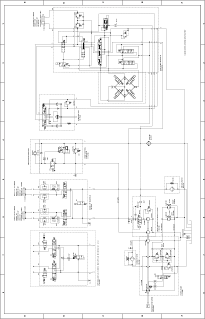
Schematics
Hydraulic Schematic 138-6255