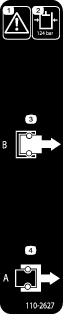
Safety
Safety and Instructional Decals
 |
Safety decals and instructions are easily visible to the operator and are located near any area of potential danger. Replace any decal that is damaged or missing. |
Installation
Preparing to Install the Kit
Note: If you are installing the remote hydraulics manifold kit on a Workman model with a serial number in the range of 240000000 through 249999999, you must replace the switch in this kit. Purchase the new switch (Toro Part No. 105-0023) from your Toro Distributor and install the switch.
-
Move the machine to a clean and level surface.
-
Shut off the engine, set the parking brake, and remove the key from the key switch.
-
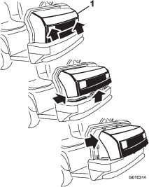
Remove the bed from the machine; refer to the Operator’s Manual for your Workman model for the bed removal procedure.
-
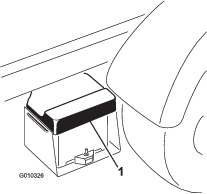
Disconnect the battery as follows:
-
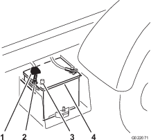
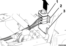
Squeeze the battery cover to release the tabs from battery base (Figure 1).
-
Remove the battery cover from the battery base (Figure 1).
-
Remove the terminal of the positive battery cable from the battery post (Figure 2).
Note: Ensure that the terminal positive battery cable does not touch the battery post.
-
-
Bleed the hydraulic pressure from the machine by fully moving the lift control for the cargo box forward and backward several times (Figure 3).
Note: You must bleed the hydraulic pressure from the machine with the engine shut off.
Removing the Hood
-
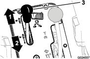
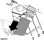
While grasping the hood in the headlight openings, lift up on the hood to release the lower mounting tabs from the slots in the bumper (Figure 4).
-
Pivot the bottom of the hood upward until the top mounting tabs can be pulled from the frame slots (Figure 4).
-
Pivot the top of hood forward and unplug the wire connectors from the head lights (Figure 4).
-
Remove the hood.
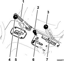
Removing the Seats (HD and HDX series models)
Removing the Center-Console Covers
-
Ensure that the parking brake is set.
-
Remove the center console covers as follows:
-
For Workman models with an manual transmission—
-
shift the differential lock to the Lock position (Figure 5).
-
remove the shifter handle and jam nut from the transmission-shift rod (Figure 5).
-
-
For Workman models with an automatic transmission—
-
move the transmission lever to the L (low forward) position (Figure 6).
-
remove the transmission lever knob (Figure 6).
-
move the speed-range lever to the A (high range) position (Figure 6).
-
-
-
Move the hydraulic-lift lever to the raise the bed position, and set the hydraulic-lift lock (Figure 5 and Figure 6).
-
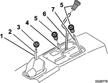
Remove the remaining knobs from console levers by rotating the knobs counterclockwise (Figure 6).
-
For Workman models with an automatic transmission remove the shift indicator as follow:
-
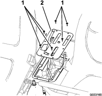
Remove the 6 hex-head screws that secure the control cover to the seat shroud, and remove the control cover (Figure 7 and Figure 8).
Removing the Coolant Tank (non-HD models), ROPS Shield, and Seat Shroud (HD and HDX series models)
Removing the CVT Cooling Duct and Coolant Tank
-
For HDX-Auto Workman models, remove the CVT cooling duct as follows:
-
For non-HD models, lift the coolant tank up and out of the support bracket on the back of the ROPS shield (Figure 11).
-
Set the coolant tank upright onto the engine/chassis.
Removing the Hydraulic Lift Lines
Disconnecting the Hydraulic Lift Hoses (3000 and 4000 series Workman)
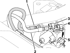
Disconnect the extend and retract hoses from the straight fittings that are connected to the male and female quick couplers at the quick disconnect bracket for the lift cylinders.
Removing the Hydraulic Lift Tubes (HD, HDX, and HDX Auto series Workman)
-
Disconnect the tube nuts for the extend and retract tubes from the straight fittings that are connected to the male and female quick couplers at the quick disconnect bracket for the lift cylinders (Figure 14).
Note: Allow the hydraulic fluid to drain from the tubes into a drain pan.
-
Remove the 5/16 x 1-1/2 inch bolt and clamp that secures the extend and retract tubes to the tube support bracket.
-
Disconnect the extend and retract tubes at the lift cylinder control valve (Figure 15).
-
Remove the tubes from the machine.
Note: Discard the tubes.
Removing the Quick Disconnect Hose Fittings and the Quick Disconnect Bracket
Removing the Quick Disconnect Hose Fittings
-
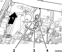
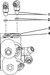
Align drain pan under the fittings at the quick disconnect bracket at the right rear of the machine (Figure 16).
-
Remove the 2 lift cylinder hoses from the quick disconnect bracket (Figure 16).
-
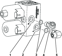
Remove the 90° fittings and the quick disconnect fittings from the end of the 2 lift cylinder hoses (Figure 16).
Note: Temporarily install a plug into the end of each hose.
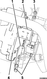
Removing the Quick Disconnect Bracket
-
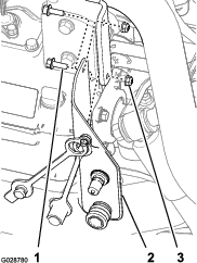
Remove the 2 flanged head bolts and 2 flanged locknuts that secure the quick disconnect bracket to the flange of the transmission support of the machine (Figure 17)
Note: Retain the flanged head bolt and flanged locknut for installation of the manifold bracket in Installing the Manifold Bracket and Hydraulic Control Manifold.
-
Remove the bracket from the machine (Figure 17).
-
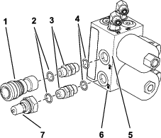
Remove the straight fittings and the quick disconnect coupling from the quick disconnect bracket.
Note: Retain the male and female quick disconnect couplings and straight fittings; discard the bracket.
Preparing the Hydraulic Control Manifold
Parts needed for this procedure:
| Hydraulic control manifold | 1 |
| Straight hydraulic fitting (11/16 x 9/16 x 3/8 inch) | 1 |
| 45° hydraulic fitting | 1 |
| 90° hydraulic fitting | 3 |
| Straight hydraulic fitting (9/16 x 9/16 x 3/8 inch) | 2 |
| Small o-ring | 4 |
| Large o-ring | 12 |
Preparing the Hydraulic Control Manifold (non-HDX-Auto Workman models)
Note: Ensure that the new O-rings are installed on the original fittings and lubricated with hydraulic fluid from the machine before installing the fittings into the manifold.
-
Install the A and B port fittings into the manifold as follows:
-
For 2000 and 3000 series Workman
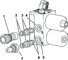
Install the 2 straight hydraulic fitting that you removed in step 3 of Removing the Quick Disconnect Hose Fittings into ports A and B of the manifold (Figure 18).
-
For HD, HDX, and HDX-D Workman
-
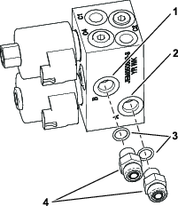
Install 1 of the straight hydraulic fittings that you removed in step 3 of Removing the Quick Disconnect Bracket into port B of the hydraulic control manifold (Figure 19).
-
Install a 45° hydraulic fitting into port A of the hydraulic control manifold (Figure 19).
-
-
-
Install 90° hydraulic fittings into ports C1 and C2 of the hydraulic control manifold (Figure 20 and Figure 23).
Note: Align the fittings as shown in Figure 20 and Figure 23.
-
Install 2 new straight fittings (9/16 x 9/16 x 3/8 inch) into ports C3 and C4 (Figure 21).
-
Install the male quick disconnect coupling that you removed in step 3 of Removing the Quick Disconnect Bracket onto the straight hydraulic fittings (9/16 x 9/16 x 3/8 inch) in port C3 (Figure 21).
-
Install the female quick disconnect coupling that you removed in step 3 of Removing the Quick Disconnect Bracket onto the straight hydraulic fittings (9/16 x 9/16 x 3/8 inch) in port C4 (Figure 21).
Preparing the Hydraulic Control Manifold (HDX-Auto Workman models)
Note: Ensure that the new O-rings are installed on the original fittings and lubricated with hydraulic fluid from the machine before installing the fittings into the manifold.
-
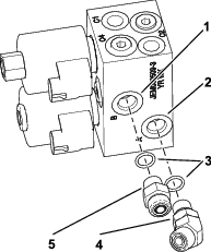
Install a 45° hydraulic fitting into port B of the hydraulic control manifold (Figure 22).
-
Install a 90° hydraulic fitting into port A of the hydraulic control manifold (Figure 22).
-
Install 90° hydraulic fittings into ports C1 and C2 of the hydraulic control manifold as shown in Figure 23.
-
Install 2 new straight fittings (9/16 x 9/16 x 3/8 inch) into ports C3 and C4 (Figure 24).
-
Install the male quick disconnect coupling that you removed in step 3 of Removing the Quick Disconnect Bracket onto the straight hydraulic fittings (9/16 x 9/16 x 3/8 inch) in port C3 (Figure 24).
-
Install the female quick disconnect coupling that you removed in step 3 of Removing the Quick Disconnect Bracket onto the straight hydraulic fittings (9/16 x 9/16 x 3/8 inch) in port C4 (Figure 24).
Installing the Manifold Bracket and Hydraulic Control Manifold
Parts needed for this procedure:
| Flat manifold bracket | 1 |
| Flanged manifold bracket (HDX-Auto Workman models) | 1 |
| Bolt (5/16 x 3/4 inch) | 2 |
| Lock washer (5/16 inch) | 2 |
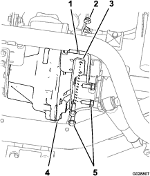
Install the Manifold Bracket (non-HDX-Auto Workman models)
-
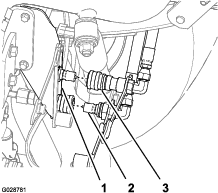
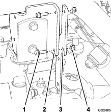
Align the holes in the flat manifold bracket to the holes in the flange of the transaxle support (Figure 25).
-
Secure the bracket to the support with the 2 flanged-head bolts and 2 flanged locknuts (Figure 25) that you removed in step 1 of Removing the Quick Disconnect Bracket.
Install the Manifold Bracket (HDX-Auto Workman models)
-
Remove the 2 flanged-head bolts that secure the right differential support to the housing of the differential (Figure 26).
Note: Retain the bolts.
-
Remove the 2 flanged-head bolts and 2 flanged lock nuts that secure the right differential support to the axle support (Figure 26).
Note: Retain the bolts and nuts; discard the old differential support.
-
Align the holes in the new right differential support with the threaded holes in the differential (Figure 27).
-
Secure the differential support to the differential with the 2 flanged-head bolts that you removed in step 1 (Figure 27).
-
Align the holes in the right differential support to the holes in the axle support (Figure 27).
-
Secure the differential support to the axle support with the 2 flanged-head bolts and 2 flanged lock nuts (Figure 27) that you removed in step 2.
Install the Hydraulic Control Manifold
-
Align the holes in the manifold with the holes on the manifold bracket (non-HDX-Auto Workman models) or right differential support (HDX-Auto Workman models) as shown in Figure 28.
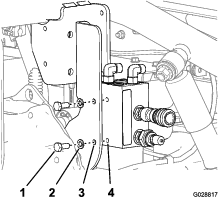
-
Secure the manifold to the bracket or the differential support (Figure 28) with the 2 bolts (5/16 x 3/4 inch) and 2 lock washers (5/16 inch).
Installing the Hydraulic Supply Hoses
Parts needed for this procedure:
| Hose (3/8 x 95 inches) | 2 |
| 3-position switch | 1 |
| Cable ties | AR |
Connecting the Hydraulic Lift Hoses (3000 and 4000 series Workman)
Connect the extend and retract hoses that you disconnected in Disconnecting the Hydraulic Lift Hoses (3000 and 4000 series Workman) to the straight fittings in port A and B of the hydraulic control manifold.
Installing the Hoses (non-HDX-Auto Workman models)
-
Install the straight fitting of the hydraulic supply hose to the straight fitting in port A (extend) of the lift cylinder control valve (Figure 29).
-
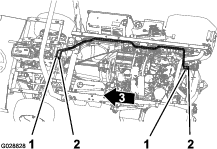
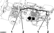
Route the hose along the right side of the machine along the path of the 2 hydraulic tubes (Figure 30) that you removed in Removing the Hydraulic Lift Lines.
-
Install the 45° of the hydraulic supply hose to the straight fitting in port B of the hydraulic control manifold (Figure 31).
-
Install the 45° fitting of the hydraulic supply hose to the 90° hydraulic fitting in port B (retract) of the lift cylinder control valve (Figure 29).
-
Route the hose along the other hose (Figure 30) that you routed in step 2.
-
Install the straight fitting of the hydraulic supply hose to the 45° hydraulic fitting in port A of the hydraulic control manifold (Figure 31).
-
Secure the hoses to the chassis with cable ties as required to support the hoses and prevent interference with moving parts of the machine.
Installing the Hoses (HDX-Auto Workman models)
-
Install the straight fitting of the hydraulic supply hose to the straight fitting in port A (extend) of the lift cylinder control valve (Figure 32).
-
Route the hose along the right side of the machine along the path of the 2 hydraulic tubes (Figure 33) that you removed in Removing the Hydraulic Lift Lines.
-
Install the 45° fitting of the hydraulic supply hose to the 45° hydraulic fitting in port B (retract) of the lift cylinder control valve (Figure 34).
-
Install the 45° fitting of the hydraulic supply hose to the 90° hydraulic fitting in port B (retract) of the lift cylinder control valve (Figure 32).
-
Route the hose along the other hose (Figure 33) that you routed in step 2.
-
Install the straight fitting of the hydraulic supply hose to the 90° hydraulic fitting in port A of the hydraulic control manifold (Figure 34).
-
Secure the hoses to the chassis with cable ties as required to support the hoses and prevent interference with moving parts of the machine.
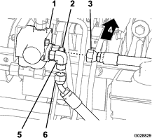
Connecting the Lift Cylinder Hoses to the Manifold
-
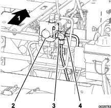
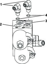
Connect the lift cylinder hose (extend) with the 90° hydraulic fitting at port C1 of the manifold (Figure 35).
-
Connect the lift cylinder hose (retract) with the 90° hydraulic fitting at port C2 of the manifold (Figure 35).
-
Replenish the transaxle reservoir (non-HDX-Auto Workman models) or the hydraulic reservoir (HDX-Auto Workman models) with the specified fluid; refer to the Operator’s Manual for your machine.
-
Ensure that all of the hydraulic fittings are tight and check for leaks.
Installing the Wiring Harness
Parts needed for this procedure:
| Wiring harness | 1 |
| 3-position switch | 1 |
| Cable ties | AR |
Important: When routing the wiring harness, keep the harness away from any hot, sharp or moving parts.
-
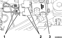
Plug the (2) connectors from the enclosed manifold harness into the solenoids on the manifold (Figure 36).
-
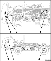
Route the wire harness as shown in Figure 37.
-
Route the wiring harness under the seat area to the front of the vehicle along the existing wiring of the machine (Figure 37).
-
Route the leg of the wiring harness with the blade socket terminal and ring terminal forward to the vehicle fuse block (Figure 37).
-
Route the leg of the wiring harness with the 8-socket connector to the lower left corner at the front of the dash panel (Figure 37).
-
Secure the wiring harness to the engine and chassis with cable ties as required to support the wiring harness and to prevent interference with moving parts of the machine.
Installing the Fuse Block
Parts needed for this procedure:
| Fuse block | 1 |
| Fuse (12 amp) | 1 |
| Decal (fuse block) | 1 |
| Bolt (5/16 x 3/4 inch) | 1 |
| Locknut (5/16 inch) | 1 |
-
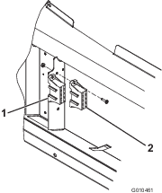
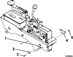
Remove the screws that secure the fuse block of the machine to the frame (Figure 38).
-
Slide the new fuse block assembly onto the side of the existing vehicle fuse block (Figure 38).
-
Mount both of the fuse blocks to the vehicle frame with fasteners removed and a #10-24 screw and locknut (Figure 38).
-
Insert the 10 amp fuse into the top slot in the new fuse block
-
Install the new fuse decal next to the fuse block.
-
Connect the red lead with the black terminal from the fuse block of the machine to the black terminal on the new fuse block.
-
Connect the red lead from the manifold harness to the red wire coming from the 10 amp fuse on the new fuse block.
-
Connect the ring terminal (ground) wire from the manifold harness to the vehicle frame or ground block.
Installing the Manifold Control Switch
Parts needed for this procedure:
| 3-position switch | 1 |
| Cable ties | AR |
-
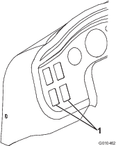
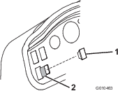
Remove a plug from one of the unused holes in dash panel (Figure 39).
-
Align the 8-socket connector for the kit wiring harness through the hole in the dash (Figure 40).
-
Connect the 8-socket connector to the blade connector of the 3-position switch.
-
Align the window for the indicator light in the 3-position switch up.
-
Insert the 3-position switch into the hole dash panel until the switch snaps securely into position (Figure 40)
-
Affix the decal to the dash panel, next to the switch (Figure 40).
-
Secure the wiring harness to the chassis with cable ties as required to support the wiring harness and to prevent interference with moving parts of the machine.
Installing the Hydraulic Lift Lever Neutral Switch
Parts needed for this procedure:
| Neutral switch | 1 |
| Locknut (10-24 inch) | 1 |
| Carriage bolt (10-24 x 5/8 inch) | 1 |
| Switch plate | 1 |
Installation of the hydraulic lift lever neutral switch pertain to Workman models that do not have the hydraulic lift lever neutral switch installed. If your machine is already equipped with a hydraulic lift lever neutral switch, skip to Installing the Seat Shroud.
-
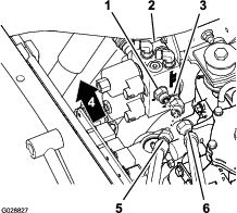
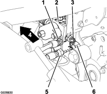
Insert the new neutral switch into the slot in the left rear corner of the control console frame and position the switch as shown in Figure 41.
Note: A different neutral switch (Toro Part No. 105-0023) is required if your HD series Workman has a serial number is in the range of 240000000 thru 249999999.
-
Loosely secure the switch in the console slot (Figure 41) with a switch plate, carriage bolt (10-24 x 5/8 inch) and locknut (10-24 inch).
Note: Make sure that the tab of the switch plate passes thru the slot and into the other hole in the neutral switch.
-
In the same area of the control console, locate the 2 connectors and jumper wires coming from the main wire harness of the machine.
-
Remove one of the jumper wires and plug that connector of the main wire harness into the connector for the neutral switch.
-
Adjust the position of the switch (forward or backward) until the target on the switch is aligned with the rod for the lift-cylinder control valve.
-
Tighten the carriage bolt and locknut to secure the position of the neutral switch (Figure 41).
-
Install the terminal of the positive battery cable to the battery post; refer to Preparing to Install the Kit.
-
Align the battery cover to the battery base, squeeze the cover, and insert the tabs of the cover into the slots in the battery base; refer to Preparing to Install the Kit.
-
Check the adjustment of the neutral switch as follows:
-
Ensure that the parking brake is set and tranasmission shift lever is in Neutral (non-HDX-Auto Workman models) or Park (HDX-Auto Workman models).
-
Move the hydraulic lift lever forward to the lower position and try to start the engine.
Note: If the engine does not start the switch is adjusted properly. If the engine starts, the position of the neutral switch is incorrect and you need to adjust it again before continuing with the rest of the installation instructions for this kit; refer to steps 5, 6, 91, and 92.
-
Installing the Seat Shroud and ROP Shield (HD and HDX series models) and Coolant Tank (non-HD models)
Installing the Seat Shroud
-
Align the opening in the seat shroud for the parking brake with the parking brake handle (Figure 6 and Figure 13).
-
For Workman models with an manual transmission, align the hole in the gear selector boot with the rod for the gear selector.
-
Align the opening in the seat shroud for the rods for the lift bed control, high-low range shifter, and the differential lock (Figure 5 and Figure 6).
-
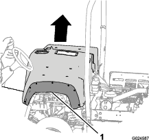
Lower the seat shroud down (Figure 13).
-
Align the holes in the shroud for the seat mounting with the seat support brackets of the chassis.
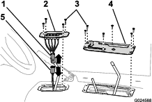
Installing the ROPS Shield
-
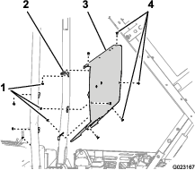
Align the holes in the ROPS shield with the hole in the brackets on the ROPS bar (Figure 12).
-
Secure the ROPS shield to the ROPS bar with the 6 carriage bolts and 6 nuts (Figure 12) that you removed in step 1 of Removing the ROPS Panel and Seat Shroud.
Installing the Coolant Tank (non-HD models) and the CVT Cooling Duct (HDX-Auto Workman models)
-
For non-HD models, align the left and right flanges of the coolant-tank bracket with the slots in the seat shroud (Figure 11); refer to Removing the Coolant Tank (non-HD models), ROPS Shield, and Seat Shroud (HD and HDX series models).
-
Lower the tank into the slots until the tank is firmly seated (Figure 11); refer to Removing the Coolant Tank (non-HD models), ROPS Shield, and Seat Shroud (HD and HDX series models).
-
For HDX Workman models with an automatic transmission, install the CVT cooling duct as follows:
-
Align the CVT cooling duct to the flange of the CVT intake at the back of the ROPS panel on the passenger side (Figure 10).
-
Secure the duct to the flange of the CVT intake with the hose clamp that you removed in step 1 of Removing the Coolant Tank (non-HD models), ROPS Shield, and Seat Shroud (HD and HDX series models).
-
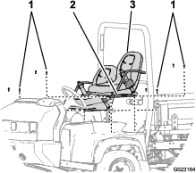
Installing the Seats and Center Console Panel (HD and HDX series models)
-
Align the holes in the seat rails with the holes in the shroud for the seat mounting positions (Figure 13).
-
Secure the seats to the chassis with the 8 socket-head bolts (Figure 9) that you removed in step 1 of Removing the Seats.
-
Torque the socket head bolts to 1978 to 2542 N-cm (175 to 225 in-lb).
-
Align the control cover over the control rods at the center console (Figure 7); refer to Removing the Center-Console Covers.
-
Secure the cover with the 6 screws (Figure 7 and Figure 8) that you removed in step 6 of Removing the Center-Console Covers.
-
For Workman models with an automatic transmission install the shift indicator as follow:
-
Connect the harness of the shift indicator to the machine-harness connector (Figure 7) that you separated in step 2 of Removing the Center-Console Covers.
-
Align the shift-indicator cover over the control rod at the center console (Figure 7).
-
-
Secure the cover with the 4 screws (Figure 7) that you removed in step 1 of Removing the Center-Console Covers.
-
For Workman models with an manual transmission, thread the jam nut and shifter knob onto the transmission shift rod, align the knob so that the shift pattern is legible, and tighten the jam nut (Figure 8).
-
Thread the control knobs that you removed in step 4 of Removing the Center-Console Covers onto the rods for the transmission lever (Workman models with an automatic transmission), hydraulic-lift, and the speed-range lever (Figure 6).
Installing the Hood
-
Align the bottom of the hood to the top of the bumper (Figure 4).
-
Connect the lights.
-
Insert the top mounting tabs into the frame slots (Figure 4).
-
Insert the lower mounting tabs into the pockets in the bumper (Figure 4).
-
Ensure that the hood is fully engaged in the top, sides, and bottom grooves (Figure 4).
Installing the Bed
For Workman models with a utility bed, install the bed onto the machine; refer to the Operator’s Manual for your Workman model for the bed installation procedure.
Operation
Using the Remote Hydraulics Manifold
Important: If the 3-position switch is left in the ON position, and the engine is shut off, the battery will drain from the solenoids in the manifold being energized. Make sure that you set the 3-way switch to the Off position before you shut off the engine.
-
If the bed operates backwards, switch the 2 hoses connected to the 90 degree fittings on the manifold.
Important: Make sure that you cycle the bed lift lever several times in order to release/equalize the pressure in the bed lift cylinders before removing the hoses.
-
The dump bed will operate normal when the 3-position switch is in the OFF position. Turning the 3-position switch ON will deactivate the bed and activate the quick coupler connections.