4G RTK Turf Pro Series Robotic Mowers and Range Pro Series Ball Pickers


Introduction
 

Manual Conventions

This manual identifies potential hazards and has safety messages identified by the safety-alert symbol, which signals a hazard that may cause serious injury or death if you do not follow the recommended precautions.
Graphic
G405934
This manual uses 2 words to highlight information. Important calls attention to special mechanical information and Note emphasizes general information worthy of special attention.
This manual is used in conjunction with the Turf Pro and Range Pro series Operators Manuals.


Safety
 

General Safety

  • The operator/supervisor of the machine is responsible for any accidents or hazards occurring to others or their property.
  • Read, understand, and follow all these instructions and warnings before using the machine.
  • Improperly using or maintaining the machine could result in serious injury or death. To reduce this potential, follow all safety instructions.
  • Do not allow children or untrained people to operate or service this machine. Allow only people who are responsible, trained, familiar with the instructions, and physically capable to operate or service the machine.

Operation Safety

  • Before operating the machine, ensure that there is a physical barrier (e. g., a low fence or a boundary wire) or that the boundary of the operating area is set at least 8 m (26 ft) away from hazards.
  • Keep bystanders and children away from the machine and charging station during operation.
  • Wear appropriate clothing, including long pants and substantial, slip-resistant footwear, whenever you manually operate the machine.
  • Do not operate the machine without all safety protective devices in place and working properly.
  • Inspect the area where you will use the machine and remove all objects that could interfere with the operation of the machine.
  • The blades are sharp; contacting the blades can result in serious personal injury. Press the stop button and wait for all moving parts to stop before unclogging, servicing, or transporting the machine.
  • Keep your hands and feet away from moving parts on and under the machine.
  • Do not overreach. Keep proper footing and balance at all times. This enables better control of the machine in unexpected situations. Walk, never run when training the machine.
  • Do not stand, sit, or ride on the machine or allow others to do so.
  • If the machine strikes an object and/or starts to vibrate abnormally, immediately shut off the machine and wait for all movement to stop before examining the machine for damage. Make all necessary repairs before resuming operation.
  • Press the stop button on the machine, wait for all movement to stop, and disable the machine in the following situations:
    • Before clearing blockages on the machine
    • Before checking, cleaning, or maintaining the machine (especially the blades), and the charging station
    • After the machine strikes a foreign object, is in an accident, or breaks down; examine the machine for damage and make repairs before resuming operation
    • If the machine begins to vibrate abnormally; examine the machine for damage and make repairs before resuming operation
  • Do not place any object on either the machine or the charging station.
  • Do not modify the machine, software, charging station, or base station.
  • Do not modify or override the machine controls or safety devices.
  • Do not use a modified machine, charging station, or base station.
  • We recommend not using the machine while watering or irrigating the operating area.
  • Use only accessories approved by Toro to avoid the risk of fire, electric shock, or injury.
  • Press the stop button on the machine and wait for the blades to come to a complete stop before handling the machine.
  • Do not connect a damaged power cord. Do not touch a live damaged cord.
  • Do not use the charging station power supply during severe weather.


4G RTK Installation Requirements
 

4G RTK allows the robot to work within an area that is not defined by a peripheral wire. This section describes the various requirements for a robot to operate using 4G RTK.

Overview of the RTK GPS

  • Standard GPS positioning data retrieved from satellites using GNSS (Global Navigation Satellite System) is accurate to between 5 m and 10 m (16.4 ft to 33 ft). This is because the signal received from a satellite is distorted due to atmospheric and environmental conditions. Higher precision positioning can be achieved by using an RTK (Real-Time Kinematic) technique.
  • This technique involves the use of an RTK base placed in a fixed position, which receives GNSS signals from satellites. Since the base is fixed, the data it receives relates to its precise location.
  • The robots are also fitted with antennas, which receive GNSS signals from satellites in order to determine their position. Both the RTK base and the robots receive the GNSS signals from satellites in different constellations (GPS, GLONASS, Galileo, BeiDou). Since the robots are moving however, the evaluation of their position is less precise than that of the fixed base.
  • The RTK base, via a cloud-based server, computes correctional data for each of the satellites and sends these to the robot. The robot uses these corrections to achieve positional accuracy. With such accurate positioning, the robot is able to follow a defined pattern and cover the field in a series of straight lines.
Corrections can also be made via the cloud using 4G cellular service. In this case, obstacles do not impede the transfer of correctional data and the base can connect to an unlimited number robots at distances of up to 15 km (9.3 mi).
Transfer of corrections using 4G Cellular Service
Graphic
G520851
One base station can feed corrections to multiple robots, but each robot must receive corrections from only 1 base station to keep corrections consistent.
Basic components of the RTK GPS mowing system
Graphic
G520852
This topic describes the mechanical characteristics of the robot.
A user can exercise direct control over the robot using the User Interface. Once a robot is registered on the portal running on a web server:
  • The robot can send information to this server which can be seen by the user.
  • The user can issue commands to the robot, assess its performance, and adjust the configuration.

Site Requirements

GPS Signal Quality
An important criteria in determining whether a site is suitable for a wireless installation is the quality of the GPS signal.
Note: The GPS signal quality close to the border of the site (along the edge of the GPS Safety Zone) must be 2.
For those areas where the GPS signal is insufficient, wired parcels can be used as part of the installation. They can be linked with other working zones and the station loop through the use of navigational paths.
GPS signal quality can vary. It depends on variables such as weather conditions, satellite constellations, and field conditions. It is important to take this into account when assessing the site.
Open Sky View
Note: It is essential for a 4G RTK installation that there is an open sky view over the entire site for the robots and the RTK base.
Trees and buildings can reduce the signal level. It is important to bear in mind that in winter, when the trees are bare, you may obtain a signal level that is higher than in summer when the trees are in leaf and when the robot needs to work.
Critical distances to buildings and trees are shown in the following figure.
Graphic
G527696
Slopes
The maximum slope allowed at the GPS boundary is 30% (17°), or 45% (24°) for slope model (S) versions.
If the RTK data corrections are being transferred using Wi-Fi, short and steep slopes can cause problems. These can cause a shadow which hides the satellite signals. In such a situation, a Wi-Fi repeater or 4G can be used.
Graphic
G527697
Distance from Hazardous Features
If the distance between a hazardous feature and the GPS Safety Zone border (X) in the following figure is less than 8 m (26.3 ft), a physical barrier of at least 15 cm (6 inches) in height must be installed.
Hazardous features would include roads and water.
Graphic
G527698
Shape and Size
The shape and size of the site is less important than the complexity of the safety zone within that site. Calculation of the GPS route depends on the overall working area, its shape, and whether it contains complexities such as narrow passages, obstacles, and No-Go zones. Large and complex sites can be managed through the use of multiple safety zones.

GPS Signal Requirements

Problems in the installation can mean that the robot does not receive a GPS signal with sufficiently high quality. The required signal levels for different operations are listed in the following sections, along with the actions that the robot takes when the signal is too low for the required operation.
Signal quality levels can be seen by using Technician's menu (9) > GPS RTK.
Border Discovery via Remote Control
Required signal level: =>2.
Robot actions: Nothing
A message is received on the smartphone app informing the user that the point cannot be registered.
Border Verification
Required signal level: =>2.
Robot actions: After 10 minutes, the robot issues the following message: Precise position lost. Check connection with reference base station.
GPS Navigation
This operation refers to the robot using GPS navigation to leave or return to the station with or without No-Go zones.
Required signal level: =>2.
GPS signal quality level must be =>2.
Robot actions:
  • After 5 minutes, the robot reboots the RTK module.
  • After 30 minutes, the robot rotates itself to better align the antenna with the satellites.
  • After 3 hours, an alarm is triggered.
Exit Station for Pattern Working
This refers to the robot exiting the station along the station loop wire.
Required signal level: >1.2.
Robot actions:
  • After 5 minutes, the robot reboots the RTK module.
  • After 3 hours, an alarm is triggered.
Leave the Station Loop to Start Working
This refers to the robot leaving the station loop wire and starting to work in pattern mode.
Required signal level: =>2.
Robot actions: After 10 minutes, the robot returns to the station using the station loop wire and tries to start the mission again.

4G RTK GPS Zones

In the absence of a physical peripheral wire, working zones are defined by GPS coordinates.
Graphic
G527699
  1. The loop wire.
  2. GPS Safety Zones. These encompass the entire working area for the robot and can surround internal working areas or paths.
  3. Internal GPS zones where the robot can work at different times and under different conditions.
  4. NoGo zones where the robot is excluded from working.
  5. A path which lies within a GPS Safety Zone.
  6. A wired zone, which can be used in areas where the GPS signal is insufficient for a 4G RTK zone.
Site Layout
The area that the robot works is defined by GPS Safety Zones that can use either peripheral wire or 4G RTK to define the borders. Additionally, internal GPS working zones can be created to control mowing frequency, patterns, or other user input.
The Station Loop Wire
A wired station loop must be used to enable the robot to access the charging station and the drop pit station. If more than one ball collecting robot is in operation, then a busy loop may be required.
The GPS Safety Zone
This defines the outer envelope of the robot's working area representing the equivalent of the peripheral wire. It is essential that the robot does not move outside of this zone.
  • At least one zone must be configured and designated as the GPS Safety Zone.
  • A safety zone can be used to enclose a working area or a path.
  • Multiple Safety Zones can be defined. For navigational purposes, they must intersect with each other.
  • At least one must intersect with the station loop wire.
  • The Safety Zone is defined by a process of border discovery. After the discovery, it is required that the Safety Zone must be verified and then confirmed.
  • The definition of the GPS Safety Zone can only be done by a user who has the User Role of Technician on the web portal.
  • The configuration parameters used to define the Safety Zone are registered. Any modifications made to these parameters require verification and confirmation.
  • If any changes to the parameters are detected (e.g., the Base position has changed) or if the connection to the base station is lost, the robot will stop operating.
  • If a single zone contains a narrow passage between edges of the safety zone, the passage must be at least 5 m (16.4 ft) wide.
    Graphic
    G527725
Internal GPS Working Zones
  • Any number of internal GPS working zones can be defined to optimize the operation of the robot; defining zones in which the robot works at particular times and frequencies.
  • The cutting height in the different zones is the same as that set for the encompassing Safety Zone.
  • All these internal zones must be within the overall GPS Safety Zone.
  • They do not need to be defined by a border discovery process. They can be defined and edited on the web portal by any type of user who has access to the robot.
NoGo Zones
NoGo zones are areas, usually around obstacles, from which the robot is excluded.
  • NoGo zones must be defined by a process of border discovery.
  • They can only be defined or modified by users who have the role of technician.
  • The border must be verified and confirmed.
  • NoGo zones need to be at least 5 m (16.4 ft) from the edge of the Safety zone and from each other.
  • NoGo zones must be a minimum of 1 m (3.2 ft) wide in all directions.
  • Long NoGo zones need to be a minimum of 5 m (16.4 ft) wide.
GPS Paths
Paths are a useful and efficient means of connecting separate working zones. These working zones can be wired parcels or 4G RTK zones. There is no limit to the number zones that can be connected by paths.
Wired Parcels
Wired parcels can be used for those areas where the GPS signal quality is insufficient to allow a 4G RTK zone to be defined.

Station and Loop

At least one loop wire must be installed around the station to enable the robot to exit and return to the station. One GPS zone must intersect with the station loop wire. While the installation may include multiple GPS safety zones (and wired parcels), only one needs to intersect with the station loop, though multiple zones may intersect with the station loop.
This section defines the critical dimensions associated with the loop for a 4G RTK installation.
Single Loop with Single GPS Safety Zone
Graphic
G527701
The following conditions apply:
  • The station loop must intersect with the GPS Safety Zone and be set as its neighboring parcel.
  • The station loop must overlap the GPS Safety Zone by at least 4 m (13.1 ft) in both directions.
  • The signal level detected by the robot when it is at the station must be at least 1.2.
  • The signal level within the overlap area must be 2.
  • The length of straight wire on the incoming and outgoing sides must be >3.5 m (6.6 ft).
  • The distance between the station and the GPS safety zone (width) must be >2 m (11.5 ft).
A GPS return point must be defined within the overlap area.
Single Loop with Multiple GPS Safety Zones
Multiple safety zones can be connected to the loop wire. This may be multiple working zones or the safety zones that surround paths.
Graphic
G527702
The following conditions apply:
  • The station loop must intersect with each GPS Safety Zone. Each one needs to be set as a neighboring parcel to the loop.
  • The station loop must overlap each GPS Safety Zone by at least 4 m (13.1 ft) in both directions.
  • The signal level detected by the robot when it is at the station must be at least 1.2.
  • The signal level within the overlap area must be 2.
  • The length of straight wire on the incoming and outgoing sides must be >3.5 m (11.5 ft).
  • The distance between the station and the GPS safety zone (width) must be >2 m (6.6 ft).
  • A mechanism must be defined to allow the robot to the station loop. This can be a GPS return point, or a path.
Multiple Loops
When multiple loops are connected to the station, the required signal levels are the same as for the single loop shown in the previous section. The dimensions associated with the loop wires are shown below.
Graphic
G527703
  • Each loop must intersect with its GPS Safety Zone and be set as its neighboring parcel.
  • The station loop must overlap the GPS Safety Zone by at least 4 m (13.1 ft) in both directions.
  • The signal level detected by the robot when it is at the station must be at least 1.2.
  • The signal level within the overlap area must be 2.
  • The length of straight wire on the incoming and outgoing sides of each loop must be >3.5 m (11.5 ft).
  • The distance between the station and the GPS safety zone must be >2 m (6.6 ft).
  • A GPS return point must be defined within each overlap area.
  • Do not use neighboring signal channels for the different station loops.
  • Wires should not be twisted.
  • Each loop should be a single line of wire.
  • The wires for Loop 1 and Loop 2 can be placed in the same slot in the ground for the charger entrance and exit.

Requirements Relating to Paths

Paths are a useful and efficient means of connecting separate working zones. These working zones can be wired parcels or 4G RTK zones. There is no limit to the number zones that can be connected by paths.
Paths Must be Enclosed within a GPS Safety Zone
Graphic
G527704
In the preceding figure, a specific GPS Safety zone was created to enclose the path that will link the two GPS zones.
It is recommended that you create separate safety zones for the paths. A GPS signal level of 2 is required in the area where the zone is to be created.
A path has a defined width. The minimum value is the width of the robot. The maximum value is 10 m (33 ft). When the robot is navigating along the path, it takes a random route between the start and the end of the path to reduce the risk of tracks occurring in the grass.
Graphic
G527705
The width of the surrounding zone must accommodate the path. It should be noted however that the robot will never go outside of the surrounding zone, even if the width of the path would allow it. Paths enable the robot to navigate along relatively narrow passages.
The maximum speed and the action of the cutting heads when the robot navigates along the path can be configured to allow zones to be connected by narrow and difficult passages.
These GPS safety path zones are created and discovered in the same way as all GPS safety zones.
Paths Must Overlap the Connecting Zones
As shown in the figure above, the path zone overlaps with both working zones. The overlap dimensions must be at least 4 m x 4 m (13 ft x 13 ft).
Graphic
G527706
If the path zone is overlapping a GPS safety zone, there is no need to set the zones as neighboring.
Paths Can Connect Wireless and Wired Parcels
Paths can be used to connect wireless and wired zones. In all 4G RTK installations, the station must be surrounded by a loop wire.
It is also possible to use wired working zones for those areas where the GPS signal level is not high enough to use a 4G RTK zone
Graphic
G527707
In all cases, the path zones must overlap the working zones with an overlap of 4 m x 4 m (13 ft x 13 ft).
When a path zone overlaps with a wired zone, the path zone must be set as the neighboring parcel as indicated in the figure above. Where the GPS path zones overlaps with other GPS safety zone, there is no need to set the zones as neighbors.
Discovering Paths
Paths are a series of GPS way points. These are defined by a discovery process as when discovering the border of a zone. The following conditions apply:
  • When discovering a path that is connecting the loop parcel, the first point to be discovered must lie in the overlap area between the loop wire and the GPS path safety zone.
  • The second point must be located outside of the loop wire.
  • Do not add too many points when discovering a path. On straight sections, a distance between points of between 3 m (9.8 ft) and 4 m (13.1 ft) is sufficient. On curved sections, the points should be closer together. Limiting the number of points keeps the navigation by the robot smooths and fast.
  • At least one point on the path must lie in the overlap zones that it is connecting.
Graphic
G527708
Path Design
When developing paths, it is better to use single long paths rather than segmented paths. This is illustrated in the following figure.
Graphic
G527709
Segmented paths are not recommended because the robot will use GPS navigation to move from the end of one path to the start of the other. This is likely to create tracks in the grass since the robot will always be following exactly the same route.
Graphic
G527710
It is also recommended to extend the paths well into the target working zone. This greatly improves the navigation used by the robot when it needs to return to the station.
Multiple paths can be configured in the same zone. The robot will automatically optimize trajectory according to the paths available and the target zone.
Automatically Detecting Path Zones
The path shown below passes through several zones. The robot automatically recognizes the zones that it passes through.
Graphic
G527711
This list appears as part of the characteristics of the path when viewed on the portal. In this example, the path would be characterized as:
  • From parcel: Loop
  • To parcel: Link 1, Zone 1, Link 2, Zone 2, Zone 3

The RTK Base

The RTK base can use either Wi-Fi or 4G to transmit data corrections to the robots. The requirements and configuration of the installation depends on the method used. Details on each of these bases are contained in the corresponding Base Manual.
The base manual includes:
  • A description of the base and its operational functions.
  • Installation requirements and procedure.
  • Troubleshooting the base.
  • Information about the Wi-Fi repeater.

Requirements Relating to Obstacles

The robot detects temporary obstacles with its sensors. This topic is concerned with permanent obstacles that the robot has to avoid when computing its working pattern and when it is working.
All such obstacles must be surrounded by a GPS safety zone, or a NoGo zone; both are regarded as safe boundaries.
The Charge Station
The station must be at least 15 m (49.2 ft) from any obstacle.
Graphic
G527718
Water
Water is especially hazardous for the robots and must be surrounded by a NoGo or a Safety Zone.
The boundary of the NoGo or Safety zone must be at least 8 m (26.2 ft) from the edge of the water.
Graphic
G527719
If the ground is sloping down to the water, a distance of at least 9 m (29.5 ft) is required between the border of the Safety or NoGo zone and the edge of the water.
Graphic
G527720
If it is not possible to have at least 8 m (26.2 ft) between the edge of the water and the NoGo zone, a physical barrier of at least 15 cm (6 inches) in height must be installed around the water.
Graphic
G527721
Dimensions Relating to Obstacles
A NoGo zone must be at least 1 m (3.3 ft) in all directions
Graphic
G527722
The minimum distance between NoGo zones is 5 m (16.4 ft).
Graphic
G527723
A NoGo zone must be a at least 5 m (16.4 ft) away from the border of the safety zone in which the robot works
Graphic
G527724
If an obstacle is less than 5 m (16.4 ft) from the border of the safety zone in which the robot is working, the border of the safety zone should be adapted to go around the obstacle. In the arrangement shown in the following figure, the border of the safety zone loops around the obstacle.
Graphic
G527725
There must be a minimum distance of 5 m (16.4 ft) between the sections of the border that approach and leave the obstacle. This means that there will be an area with a width of at least 5 m (16.4 ft) where the robot does not work. To overcome this, you can use two overlapping safety zones.
Graphic
G527726


Implementing a 4G RTK Installation
 

Installation Components
Image
Entire Site
Wireless Navigation requires a high GPS signal quality. If the site is surrounded by trees or buildings that impede the view to the satellites of the base and the robots, a wireless navigation system may not be possible.
GPS Safety Zone
GPS Safety Zones are areas that define the robot's working area or the area surrounding a path that the robot uses for navigation. The border of these safety zones is discovered by the robot being moved around the site. To ensure that the robot stays within a safety zone, a number of key configuration parameters are defined. If any one of these is modified, safety zones become invalid and the robot will cease operation.
Station
The charging station.
Station Loop
A wired loop parcel must be defined for the robot to return to and leave the station. This station loop wire must intersect with one GPS Safety Zone.
Paths
Paths are strings of GPS points that form a route for the robot to navigate between the station and the working areas. A path must be enclosed in a safety zone.
RTK Base
An RTK base must be installed to communicate with the satellites and then to communicate the exact position to the robots. This communication can be made using 4G or Wi-Fi. If using Wi-Fi, it may be necessary to use a Wi-Fi repeater. Details about the base can be found in the relevant Base Manual.
Wi-Fi repeater
When Wi-Fi is being used to communicate the corrections to the robot, it may be necessary to use one or two Wi-Fi repeaters to cover the entire site.
GPS defined internal working zones
Any number of GPS defined zones can be defined to create different working areas. These must be located within the overall GPS Safety Zone. They do not need to overlap with the station loop. They do not need to be defined by a border discovery process.
Permanent Obstacles
These are items such as trees, outbuildings, ponds or playgrounds that the robot must avoid. In most cases, a No-Go zone is required to ensure these are reliably avoided.
No-Go Zone
These are areas defined by GPS coordinates where the robot will not work in order to avoid obstacles.
Robot
The robot must be equipped with a GPS antenna so that it can communicate with satellites and the RTK base.
Smartphone App
The Turf Pro smartphone app enables you to define and verify the outer GPS Safety Zone.
Web portal
The robot must be connected to the turfpro.toro.com web portal.

Planning the Installation

An installation without a peripheral wire requires a stringent set of criteria to be met. Assess the criteria laid out earlier in this manual before starting the installation.
Assessing the Site
  1. Verify that there is a clear sky view for the robots and the base.
  2. Verify the GPS signal is strong.
Making a Plan
  1. Make a blueprint of the site layout.
  2. Decide on the location of the station and loop(s).
  3. Decide how many safety zones are required. This will depend on the complexity of the site.
  4. Decide how the robot will navigate from the loop to the working safety zone(s).
  5. Decide on the location of the base.
  6. Decide whether to use 4G or Wi-Fi.
  7. Decide on the location of Wi-Fi repeaters if required.
  8. Decide on the number, size and shape of the internal GPS working zones needed.
  9. Decide on how to deal with obstacles. These can be managed with NoGo zones, by the shape of the GPS Safety Zone or physical barriers.
  10. If in doubt, consult your dealer/distributor for help and advice.
Before You Start
  1. Charge the robot using the charging station.
  2. Update the software to the latest version.
  3. Check on the quality of the surface of the site.
    1. Fill in the depressions in the surface where puddles may form.
    1. Ensure that the grass is cut to a maximum height of 10 cm (4 inches).
    Note: A complete 4G RTK installation can only be performed by someone who has the user role of technician.
Installing the RTK Base, Station, and the Loop
  1. Install the base at the chosen position. Refer to the RTK Base Operators Manual.
  2. Install the charging station at the chosen location. Refer to the Charging Station Operators Manual.
  3. Install the station loop, per the instructions earlier in this manual.

Connecting the Robot to the Base

The method by which the robot is connected to the base depends on the whether Wi-Fi or 4G is being used for the communication between them.

A 4G RTK installation requires password protection for the Wi-Fi connection. Software version 3.0.0 or higher is required for the base. Details on upgrading the software can be found in the relevant RTK Base manual. If the base software has been upgraded, the password will be defined during the upgrade. Otherwise, the default Wi-Fi password can be found on the identification label of the RTK base. You are required to create a new password.
Connecting to the Base for Wi-Fi
Graphic
G539289
  1. The initial/default password for the base Wi-Fi
  2. The serial number of the base
To connect the robot to the base:
  1. On the robot press 9 to obtain the technician's menu.
  2. Select GPS RTK > > RTK Wi-Fi Connection.
  3. Enter the default password for the base.
Connecting to the Base for 4G
Note: The RTK 4G functionality on the robot needs to be activated from the portal or the smartphone app.
  1. Ensure that the robot is switched to the On position and is online.
  2. Log on to the portal or smartphone app.
  3. Graphic
    G527736
  4. Select the robot and click on Parameters.
  5. Click on Image to download the latest configuration parameters from the robot.
  6. Select Edit Parameters.
  7. Select the RTK Base tab.
    Graphic
    G540117
  8. Set the RTK connection parameter to Mobile.
    For serial numbers 324000000 through 324999999
  9. Enter the base ID number. This can be found on the base label and the QR code.
    Note: Do not use any spaces when entering the base ID number.
    Graphic
    G539289
    1. The initial/default password for the base Wi-Fi
    2. The serial number of the base
    For serial numbers 325000000 and up:
  10. Enter the base ID number for the base. This can be found on the base label and the QR code.
    Note: Do not use any spaces when entering the model and serial number for the base. XXXXX-000000000
    Graphic
    G542400
    1. Base ID serial number Model-Serial
    2. Initial/Default password for the base ID
    3. Area blank
    Graphic
    G542398
  11. Tap Image to upload the new setting to the robot.
  12. Switch the main robot switch to the Off position, then turn back On and push the power button on the keypad.
  13. Wait until the Uplink Status shows that it is Connected.
  14. Signal quality should be 2.0. Signal quality levels can be seen by using Technicians menu (9) > GPS RTK.
    Note: This may take a few minutes.

Controlling the Robot Remotely from the Smartphone App

The Turf Pro smartphone app allows you to remotely control the movements of the robot. This means that you can carry out a border discovery without having to manually push the robot.
The procedure consists of two stages:
  • Setting up the app
  • Remotely controlling the robot
Note: The app only needs to be set up once.
Setting up the App
Note: Remote control can only be set up by a portal user who has the role of Technician.
  1. On your smartphone, download the latest version of the app.
  2. Enable Access Point on the robot.
  3. Push the Service Setting Menu button.
  4. Navigate to Connections.
  5. Change from Client to Access Point.
    Note: This will show the serial number of the robot as the access point.
  6. You are required to create a new password. The default password is 12345678. When a new password has been created, select the check mark icon.
  7. Select X to return to the main mission screen.
Connecting to the Robot
  1. Connect the phone to the internet and open the Toro Turf Pro app.
  2. When you see the robots listed, open the Wi-Fi menu for the phone.
  3. Disconnect from the current Wi-Fi and connect to the robot. The robot will be identified in the Wi-Fi list as the robot serial number.
  4. Enter the password created in the previous section.
  5. Select connect. If prompted, check the box indicating that you want to stay connected to the network without internet.
  6. Return to the Toro Turf Pro app.
  7. Open the menu and select Robot Wi-Fi access.
  8. When asked if the robot is set to Access Point, select OK.
  9. Select OK when prompted to verify you are connected to the robot access point.
Remotely Controlling the Robot
Once you have set up the app, select the Remote control button, and press the check mark on the robots interface. This will allow you to start remotely controlling the robot using the joystick.
Note: It is recommended that you stand behind the robot as you control it.
While the robot is being remotely controlled:
  • The robot adheres to all safety requirements.
  • The cutting heads are deactivated.

Collisions: if one of the following faults is detected, the robot will stop but the remote control will remain active:
  • BumperLeft, BumperRight
  • Lift1, Lift2, Lift3, Lift4, Tilt
  • CollisionLeft, CollisionRight
If one of these faults remains active for more than 30 seconds, it will become a long collision and therefore a major fault. In this case, the remote control will be disabled.
Major Fault: If one of the following faults is detected the remote control will be disabled.
  • ManualStop, LongCollision ShuttingDown
  • LeftWheelMotorBlocked, RightWheelMotorBlocked
  • LeftWheelMotorTooHot, RightWheelMotorTooHot
Remote control must be re-selected before it is accessible again.

Creating a GPS Safety Zone

The border of the GPS Safety Zone is of critical importance in a 4G RTK installation. It defines the limit of the area in which the robot can operate. This can be either a working zone or a zone that surround a path. The GPS signal level over the entire safety zone should be 2. This is particularly important at the border.
Note: The creation of the GPS Safety Zone can only be done by a user who has the User Role of Technician on the web portal.
Recommended Techniques for Border Discovery
To ensure good results when the robot is mowing the border it is recommended that you mark the cutting width on the back of the robot with tape. This makes it easier to visualize the actual edge of the cut area.
Graphic
G527748
The cutting width (X) is 1033 mm or 40.6 inches (i.e., 516.5 mm or 20.3 inches from the center of the robot). The border is discovered by controlling the robot using the smartphone app.
GPS points are added at intervals to define the border.
Note: Do not add too many points. On straight stretches, one point every 3 to 4 m (9 to 13 ft) is sufficient. More points should be added on curves
Graphic
G527749
Create curves at the corners, not sharp angles.
Graphic
G527750
Note: Angles must be rounded with a minimum radius of 1 m (3.2 ft).
Graphic
G527751
For the curve defining the border to be considered valid:
  • The overall shape of border may be convex or concave.
  • There must be no crossing over of points.
Graphic
G527752
Note: On the difficult sections of the border, mark the border to help in guiding the robot along the required border.
The points on the curve can be edited (moved or removed) from the web portal or app. The points can also be removed using the smartphone app during the border discovery.
Creating the GPS Safety Zone
You can create the GPS Safety zone in the following locations:
  • On the smartphone app (recommended)
  • On the robot
  • On the web portal
?.1 On the Smartphone App
Note: This process requires you to have set up the app and it is connected to the robot.
  1. Open the menu and select Robot Wi-Fi Access.
  2. On the Robot Wi-Fi Access screen select Discover GPS Object.
  3. On the Select GPS zone to discover screen, click on the + button at the top of the screen to create a new zone.
  4. On the Creat New GPS Object screen, select GPS Safety Zone.
  5. On the Create New GPS Zone screen, enter the name for the zone.
  6. Click in the Select a neighboring parcel field and select a suitable option:
    • If this is the safety zone that is going to overlap with the station loop wire parcel, then select the this station loop parcel
    • If this is a safety zone that is not going to be connected to the station loop wire, then you can select None
  7. Tap Save Settings.
?.2 On the Robot
  1. On the robot select Technician's menu (9) > Infrastructure > Parcels > Create.
  2. Confirm that you want to create a new GPS zone.
  3. Edit the name.
  4. Select 9 Neighboring parcels. If the safety zone overlaps with the loop, check the option ON for the LOOP parcel. If the safety zone is overlapping with other GPS safety zones, you can select the option "None".
?.3 On the Portal
  1. Select the robot and click on Parameters.
  2. Tap Image to ensure you have the latest configuration parameters available on the robot.
  3. Click on Edit GPS configurationImage.
  4. Click on + next to GPS Parcels.
  5. Select GPS Safety Zone.
  6. Enter the name for the safety zone.
  7. Click in the Select a neighboring parcel field and select a suitable option:
    • If this is the safety zone that is going to overlap with the station loop wire parcel, then select the this loop parcel.
    • If this is a safety zone that is not going to be connected to the station loop wire, then you can select "None".
    Remember that one GPS Safety Zone must be connected to the loop wire parcel.
  8. Select save settings.
  9. Tap Image to transfer the new setting to the robot.
Discovering the GPS Safety Zone
This must be done remotely, by controlling the robot with the smartphone app.
  1. On the smartphone app select the safety zone that needs to be discovered.
  2. Open the lid on the robot and press the check mark.
  3. Standing behind the robot, move it along the border, adding GPS points using the + button.
    Note: Do not add too many points. On straight sections, the recommended distance is 3 to 4 m (9 to 13 ft). The points can be closer together on curved sections.
  4. Add the last point before you return to the start point.
  5. Tap the green check mark when the circuit is complete. The app will close the circuit and compute the polynomial that is formed by the GPS points. It will then check if the polynomial defining the border of the zone is valid.
  6. If the message New GPS zone is valid appears, tap OK, then tap the save icon. The points defining the border that has been discovered can be viewed and modified on the web portal.
Verifying the Border on the Robot
  1. On the robot select Technician's menu (9) > Infrastructure > Parcels > {Name of the safety zone} > Verify GPS border and press the check mark.
  2. Watch the robot as it follows the border that has just been discovered.
  3. Confirm when complete on the robot.

Setting a GPS Return Point

A GPS return point is required to enable the robot to return to the station. This point must be defined inside the loop wire and inside the safety zone. This is area A in the following figure.
Graphic
G527760
  1. Position the robot at a point that is at least 5 m (16 ft) away from the loop wire, and in a direction that is perpendicular to the loop wire. The following figure shows three valid positions for the example shown in the previous figure.
    Graphic
    G527761
  2. Push the robot forward until it is inside the loop and at the point where the GPS return point is required.
  3. On the robot select Technician's menu > Infrastructure > Parcels > {Name of the GPS Safety zone} > Neighboring parcels.
  4. Check the button next to the loop ON. This will create a point that will guide the robot from the safety zone into the loop.
  5. Select GPS points > Set.
  6. Confirm the setting.

Creating Additional Safety Zones

Any number of Safety Zones can be included in the installation. Each one defines a separate area where the robot can work.
The following criteria apply:
  • One zone in the overall configuration must overlap with the station loop wire.
  • Every safety zone must overlap with other GPS safety zones, the loop wire, or a wired parcel to enable the robot to navigate over the entire site.
  • This overlap must be at least 4 m x 4 m (13 ft x 13 ft).
  • A Safety zone must be created by a user who has the User Role of Technician on the web portal.

Creating Internal GPS Working Zones

Internal GPS working zones can be created within a safety zone. These can be used to optimize the working of the robot through scheduling.
The following conditions apply:
  • All these internal zones must lie within a GPS Safety Zone.
  • They do not need to be defined by a border discovery process. They can be defined and edited on the web portal by any type of user who has access to the robot.
  • The cutting height in the different zones is the same as that set for the encompassing safety zone.
The creation of a GPS zone can be done either on the robot, or on the web portal.
.1 Creating and Discovering a GPS Working Zone on the Robot
  1. On the robot select Technician's menu (9) > Infrastructure > Parcels > {Name of the Safety Zone} > Create.
  2. Confirm that you want to create a new GPS zone.
  3. Edit the name.
  4. On the smartphone app, select the GPS working zone that needs to be discovered.
  5. Open the lid on the robot and press the check mark button.
  6. Standing behind the robot, move it along the border adding GPS points using the + button.
  7. Add the last point before returning to the starting point.
  8. Tap the check mark button when the circuit is complete. The app will close the circuit and compute the polynomial that is formed by the GPS points. It will then check if the polynomial defining the border of the zone is valid.
  9. If the message "New GPS zone is valid" appears, tap OK, then tap the save icon. The points defining the border can be viewed and edited on the web portal.
    Note: This zone does not need to be verified.
    Other GPS working zones can be added in the same way. These zones can be used to optimize the working schedule of the robot.
.2 Creating a GPS Working Zone on the Portal
You can create an internal working zone in two ways:
  • Defining a new set of points
  • Copying and modifying an existing zone
  1. Select the robot on the portal and click on Parameters.
  2. Tap Image to ensure you have the latest configuration parameters available on the robot.
  3. Click on Edit GPS ConfigurationImage.
  4. Click on the + button next to GPS parcels.
  5. Select GPS zone inside GPS safety zone.
  6. In the GPS Zone name field, enter the name for the zone.
  7. Click in the "Select a GPS safety parent parcel" field and select the parent zone.
  8. To create a completely new GPS zone select "Default values" in the "Copy GPS coordinates from" field. To copy an existing zone, select the name of the zone to be copied.
  9. Click SAVE SETTINGS.
  10. Tap Image to transfer the new setting to the robot. Follow the required set of instructions to create a new zone or modify an existing one.
  11. Follow the required set of instructions to create a new zone or modify an existing one.
.2.1 Discovering a New GPS Working Zone on the Portal
  1. Click on Image next to the zone you have just created.
  2. Click on the map to define each of the points that will form the new GPS zone.
    Graphic
    G527766
    When the shape is closed, the new GPS zone will be created.
    Graphic
    G527767
    Other GPS internal zones can be created in the same way.
    Note: All points must be in the safety zone.
  3. Tap Image to transfer the new setting to the robot.
.2.2 Modifying an Existing GPS Working Zone on the Portal
  1. Select the zone you have just created.
  2. Click on the Image to unlock the zone. The icon will change to Image.
  3. To move a point, drag it to the new position.
  4. To delete a point, click on it.
  5. To select a number of points, click on Image, then drag a box around the points to be deleted.
    Note: All points must be in the safety zone.
  6. When the modifications are complete, click Image. This will change the icon to Image.
  7. Tap Image to transfer the new setting to the robot.

Creating a NoGo Zone

NoGo zones are a means of avoiding permanent obstacles. In the absence of a peripheral wire, it is important that you are aware of the conditions relating to the avoidance of obstacles before you create them. Permanent obstacles and the means of avoiding them should be set out on the installation plan.
You also need to take into account the dimensions described below before defining the NoGo zone.
Graphic
G527771
As can be seen from the preceding figure, when the robot is performing the border discovery or working in a direction parallel to the border, the location of the registered point on the border of the NoGo zone will be a distance X away from the actual area to be excluded. X is half the width of the robot's body 639 mm or 25.2 inches.
When the pattern direction is perpendicular to the edge of the area, the robot will stop when the center of the axle between the rear wheels reaches the registered position of the border of the NoGo zone. In this case, the registered GPS position of the border of the NoGo zone will be a distance Y away from the robots front. Y is the distance between the centre point of the rear axle and the front of the body 802 mm or 31.5 inches. When the pattern direction is perpendicular to the edge of the area, the nose of the robot will enter further over the border of the NoGo zone compared to the side of the robot when the pattern is parallel to the edge of the area.
To avoid the robot entering the area to be excluded or colliding with an obstacle, a minimum distance of 300 mm (12 inches) between the excluded area and the side of the robot should to be respected when registering the NoGo zone.
The robot will work up to distance Z from the defined margin (which should be a minimum of 300 mm (12 inches) (from the side of the robot) when registering the zone. For the robot, Z is 123 mm (4.8 inches).
Graphic
G527772
There are three methods whereby you can create a NoGo zone:
  • On the robot
  • On the smartphone app
  • On the portal
Creating and Discovering a NoGo Zone on the Robot
  1. On the robots UI, select Technician's menu > Infrastructure > GPS NoGo zones.
  2. Select Create.
  3. Enter a name for the NoGo zone.
  4. Select Manual NoGo zone discovery.
    Note: The GPS signal quality must be 2.
  5. Select Add a new GPS point. The Number of GPS points will now be 1 in the Manual NoGo zone Discovery screen.
  6. Move the robot to a new position and select Add a new GPS point again. Continue until you have positioned the robot in a set of points that encircle the zone to be excluded. You need to add enough points to define the zone to the accuracy you require, but if you add too many points, it will slow the robot down in its operation.
    Note: The NoGo zone will need to be verified.
Verifying the NoGo Zone
Verification of the NoGo zone must be done on the robots UI.
  1. Select 9. Technician's menu > Infrastructure > GPS NoGo zones and select the NoGo zone you have just created.
  2. Select Verify GPS border. Confirm that you want to verify the border.
  3. Watch the robot as it moves around the border. if you approve of the border, click OK. If not, click Cancel and start the process again.
Creating and Discovering a NoGo Zone on the Smartphone
This process requires you to have set up the app, and that the app is connected to the robot.
  1. On the Robot Wi-Fi Access screen, select Discovery GPS object.
  2. On the Select GPS zone to discover screen, click on Image at the top of the screen to create a new zone.
  3. Select GPS NoGo Zone.
  4. Enter a name for the zone.
  5. Tap Save Settings.
  6. On the smartphone app, select the NoGo zone that is being created
  7. Push Image on the robots interface and close the lid.
  8. Standing behind the robot, move it using the joystick and add a GPS point by tapping the + button. Add more points until the border of the zone has been defined. There must be at least 3 points.
  9. Tap the check mark button.
  10. The app will then check if the points you have added form a valid polynomial. If it is, you can tap Save. If it is not, you can tap the trash can icon to delete the points and start again.
Creating and Discovering a NoGo Zone on the Portal
  1. Select the robot and click on Parameters.
  2. Tap Image to ensure you have the latest configuration parameters available on the robot.
  3. Click on Edit GPS ConfigurationImage
  4. Click on + next to GPS NoGo zones.
  5. In the GPS Zone Name field, enter the name for the NoGo zone.
  6. To create a completely new GPS zone, select Default valuesin the Copy GPS coordinates fromfield.
  7. Click SAVE SETTINGS.
  8. Click on Imagenext to the NoGo zone you have just created.
  9. Click on the map to define each of the points that will form the new GPS zone.
    Graphic
    G527775
  10. When the shape is closed, the new NoGo zone will be created.
    Graphic
    G527776
  11. Tap Image to transfer the new setting to the robot.

Creating GPS Paths

Paths provide an efficient means for the robot to navigate between working zones and the station. Since they operate in both directions, they can be used for leaving and returning to the station. A typical example of the use of a path is to provide a route between the station and its loop and the working zone. This means that the station can be installed in a convenient position away from busy areas. Paths can also be used to navigate between widely separated working zones.
Paths can be created on the smartphone app or the portal.
Creating a Safety Zone to Surround the Path
All paths need to be set inside a safety zone which overlaps with the zones it is connecting. The overlap with the path zone and the loop or the working zone must be more than 4 m x 4 m (13 ft x 13 ft).
Graphic
G527777
Create all the path safety zones before you start creating paths.
Note: The working % for the safety zone around a path must be set to 0%.
These zones are considered Safety Zones and therefore are created by the same process as a Safety Zone defined earlier.
.3 Creating the Path on a Smartphone App
  1. On the Robot Wi-Fi Access screen, select Discovery GPS object.
  2. On the Select GPS zone to discover screen, click on Image at the top of the screen to create a new zone.
  3. Select Create GPS Path.
  4. Create path.
  5. Enter the name for the path.
    Note: You do not need to select parent parcel.
  6. Tap in the Connection to wired parcel field and select a suitable option.
    • If this path is going to start in the overlap with the station loop parcel, then select this loop parcel.
    • If this path is in a safety zone that is not connected to the station loop wire, then you can select None.
  7. Tap Save Settings.
.4 Discovering the Path on a Smartphone
This has to be done by remotely controlling the robot from the smartphone app. This requires you to have set up the app.
  1. Position the robot on the first point of the path.
    Note: When a path starts from the station loop, the 1st point of the path needs to be positioned inside the overlap between the station loop and path safety zone connected to the station loop.
  2. On the smartphone app, select the path that is going to be discovered.
  3. Standing behind the robot, move it along the path adding GPS points using the + button.
    Graphic
    G527708
  4. The second point needs to be positioned outside the station loop. The discovery of the path should always go from the station loop towards the other zones.
  5. Do not add too many points. On straight sections the recommended distance between points is 10 m (33 ft) for paths. The points should be closer together on curved sections.
  6. Extend the path into the zone. This aids the navigation when the robot needs to return to the station.
  7. Tap the check mark button when the path is complete. The app will compute the polynomial that is formed by the GPS points.
  8. Click the Save icon.
    Note: The points defining the path that has been discovered can be viewed and modified on the web portal.
.5 Creating a Path on the Portal
  1. Select the robot and click on Parameters.
  2. Tap Image to ensure you have the latest configuration parameters available on the robot.
  3. Click on Edit GPS configurationImage.
  4. Click on + next to GPS paths.
  5. Leave the Automatic setting ON.
  6. Enter a name for the path.
  7. Click in the Connection to Wired Parcel field and select a suitable option.
    • If this path is going to start in the overlap with the station loop wire parcel, then select this loop parcel.
    • If this path is in a safety zone that is not connected to the station loop wire, then you can select "None".
  8. Click Save Settings.
  9. Tap Image to transfer the new setting to the robot.
  10. You can now discover the path on a smartphone described above or continue on the portal.

Discovering a Path on the Portal

Note: All points must be in a safety zone.
  1. Click on Image next to the path you just created.
  2. Click on the map to define each of the points that will form the new GPS zone.
  3. Click on the first point as shown in the following figure.
    Graphic
    G527708
  4. The second point must be positioned outside the station loop. Path discovery should always go from the station loop towards the other zones.
  5. Do not add too many points. On straight sections, the recommended distance between points is 10 m (32.8 ft) for paths. The points should be closer together on curved sections.
  6. Extend the path into the zone. This aids the navigation when the robot needs to return to the station.
  7. Hover over the last point and click This will complete the path and save it.
  8. Tap Image to transfer the new setting to the robot.

Setting the Mowing Direction

This procedure enables you to ensure that the robot mows in a direction that corresponds to the definition of the sports field or pitch. This procedure assumes that the sportsfield or pitch has been setup for pattern mowing (i.e. the GPS RTK zone corresponding to the sports field or pitch has been created).
This procedure enables you to set primary and secondary working directions.
Before starting this procedure you should check that the GPS signal quality is at least 1.6.
Technician's menu (9) > GPS RTK > GPS signal quality.
  1. Position the robot at a point that will be used as a reference point to define the direction (Point 1 in the following figure). It is recommended that this point is near a corner of the pitch.
    Image
  2. Select Technician's menu (9) > Infrastructure > Parcels > {RTK GPS zone corresponding to the pitch). Check that the option Pattern mowing is checked on.
  3. Select Main heading.
  4. Select Set ref. point.
  5. Push the robot at least 10 m (32.8 ft) in the exact direction in which the pattern is to be established (Point 2 in the preceding figure). It is recommended to move the robot the maximum distance possible, to ensure the most accurate measurement of the direction.
  6. When you have moved the robot more than 10 m (32.8 ft), you can define the second point. Select Set main heading.
  7. The angle (a) between robot's orientation and due North is displayed.
    Graphic
    G527780
    If you are not happy with the angle, select Delete ref. point and start the process again.
    It is also possible to set the other mowing directions relative to the main one. To do this select Other headings, then select the Number of directions and Angle between each of these directions.
  8. When the direction is defined, save the settings.

Configuring the Installation

Choosing the Cutting Disc Type
If your working area is to be mowed at a lower height of cut, (less than 20 mm or 0.8 inches) then you can opt to use a "low height" cutting disc. The range of the low height cutting discs is 15 mm (0.6 inches) and 90 mm (3.5 inches).
  1. Select Technician's menu (9) > Advanced parameters..
  2. Select Cutting disc and select Low height.
  3. Set the required cutting height.
Setting the Cutting Height
The cutting height of the blades can be set for each safety zone that is defined in the installation. It is not possible to set different cutting heights for internal working zones; these must take the same cutting height as the parent safety zone.
Note: Cutting is not enabled by default when the robot is navigating along a path.
Setting the Cutting Height on the Web Portal
  1. Log on to the portal and click on the robot in the list.
  2. Click on Parameters.
  3. Click on Image to download the latest configuration parameters from the robot.
  4. Click on Edit Parameters gear icon.
  5. Click on the Parcel Parameters tab.
  6. Set the cutting height to the required value.
  7. Click on the X icon to close the Parameters editor window.
  8. Click Image to upload the new setting to the robot.
Setting the Cutting Height on the Robot
  1. On the robot UI, select Settings > Cutting height.
  2. Select the GPS Safety Zone to change the cutting height.
  3. Click Set target. Select the parcel to change the cutting height.
  4. Enter the required height and tap the check mark icon.
Setting the Cutting Height on the Smartphone App
  1. Log on to the app and select the robot.
  2. Tap Settings..
  3. Tap Image to ensure you have the latest configuration parameters available on the robot.
  4. Tap Setings.
  5. Tap Image.
  6. Set the cutting height to the required value.
  7. Tap Image to transfer the new setting to the robot.
Defining the Working Schedule
The working schedule for the robot can be defined either by defining a time schedule or by setting a percent of time to be allotted to each working zone.
A schedule can be most easily defined on the web portal.
Border Mowing
It is important in a 4G RTK installation that the border of the safety zone is mowed regularly.
Note: It is strongly recommended that you use sequential sequencing to manage the borders.
When sequential sequencing is implemented, the border will always be mowed as soon as the working zone has been completely mowed.
Implementing Sequential Sequencing
  1. On the robot UI, select Service Settings > Operations.
  2. Select Sequential Schedule and check the button ON.
  3. A list of parcels/zones including paths is presented. Check those to be included in the sequence ON.
  4. If you don't want the border of a zone to be included in the sequence, select Settings > Border and define the border settings.
    Note: The borders of NoGo zones are not mowed.
Configuring the Exit Station Parameters
A GPS signal level of 1.2 is sufficient for the robot to exit the station, but a signal level of 2 is required for the robot to operate in the safety zone. When it exits the station, the robot needs to travel a distance X along the loop wire before it encounters a suitable signal level of 2. This distance X needs to be set as an exit parameter.
This parameter can be set manually, but it is recommended that you allow the robot to set them automatically.
Manually Setting the Exit Parameters
  1. Select Technicians menu (9) > Infrastructure > Stations > Manual station > Exit parameters.
  2. Select Create new parameter set.
  3. Set the distance X as the Min exit distance. The minimum value that can be entered is 0.8 m (31.5 in).
  4. Enter the required value for the Max exit distance. This can be 1 m (3.3 ft) more than the minimum exit distance.
Automatically Setting Exit Parameters
  1. Position the robot at the charging station.
  2. Select Technicians menu (9) > Infrastructure > Stations > Manual station > Calibrate now.
  3. Confirm that you wish to calibrate the station. The robot will make a circuit of the loop. It will set the Min exit distance to the distance travelled before the GPS signal level of 2 is registered. The Max exit distance will be set to 1.0 m (3.3 ft) more than the minimum value.
  4. Confirm to accept the values.


How the TurfPro works in a 4G RTK Installation
 

Exit Station

The robot will leave the station when:
  • The battery has been fully charged
  • The work schedule dictates it
The way that the robot leaves the station and enters the GPS Safety Zone depends on the configuration of the installation.
  • The station loop overlaps the working area
  • The robot uses one or more paths to navigate to its working area
Station Loop Overlaps the GPS Safety Zone
Graphic
G527673
The robot must detect a GPS signal level of at least 1.2 when it is at the station. When it leaves the station it will follow the loop wire for a distance (X) until it has entered the GPS Safety Zone and it detects a GPS signal level of 2.
This distance X can be set as an installation configuration parameter to ensure that the robot travels a sufficient distance to detect a GPS signal level of 2. To set a minimum and maximum distance to be travelled when leaving the station, select Technician's menu > Infrastructure > Stations > Exit parameters.
Once the robot reaches the Safety zone and detects a GPS signal level of 2, it stops and calculates the route towards the point at which it is scheduled to work. It sets the cutting height to the value set for the GPS Safety Zone, and then rotates away from the wire and uses GPS to navigate to where it is to start working.
The Robot uses One or More Paths to Navigate to its Working Area
For large and complex installations, paths provide an efficient means of navigation to the working zones. Paths must be enclosed within safety zones, and one safety zone must overlap with the station loop wire.
The robot will leave the station and move along the track wire until it senses that it has entered a safety zone. The robot will then rotate away from the wire and move to the end of the path that will lead to the zone where it needs to work. It will move along the path using a random offset from the path to ensure that traces are not left in the grass.
When the robot senses that it has entered the working safety zone where it needs to work, it will move away from the path towards the point where it needs to start working.
Graphic
G527674

Working

Once the robot has left the station, it will navigate to the next working area.
Working in a Simple Area
The robot will navigate to the start point of the pattern it has calculated for this zone and start working using an overlap of 10 cm (4 inches) for each line of the pattern. It will continue in this manner until it needs to return to the station.
Graphic
G527675
Graphic
G527676
The mowing pattern is executed over multiple working cycles. At the start of each new cycle, the robot resumes its pattern, by default, at the exact point where the previous cycle ended. It is also possible to resume mowing at the start of the line that was incomplete at the end of the previous cycle.
Once the pattern is complete, the robot will recalculate a new mowing pattern and will rotate the mowing direction to ensure optimal cutting quality and full coverage of the field. In the example shown in the following figure, 4 directions are specified with angles of 45° between them. It is possible to use fewer mowing directions if required.
Graphic
G527677
Working in a Complex Area
When operating in a more complex working area, the area is subdivided depending on the direction of the working pattern.
Graphic
G527678
The robot will first work in sub-area 1 in a particular direction (X). Coverage of a subarea can require more than one cycle.
Graphic
G527679
When subarea 1 has been completed, the robot will move directly to start mowing subarea 2 in the same direction (X). A new cycle is not started.
Graphic
G527680
When the entire area has been completed, the robot will return to the station to charge. It will then compute new subareas that will cover the working area when working in a new direction (Y). A new working cycle will begin.
Graphic
G527681
When subarea 3 has been completed, the robot will move directly to start mowing subarea 4 in the same direction (Y). A new cycle is not started.
During pattern mowing, the robot turns before the edge of the defined mowing area. It is important to make sure that the robot mows the border regularly.

Choosing Where to Work

When there are multiple areas (GPS Safety Zones) which need to be mowed, it is important that each zone is mowed according to its needs and during the times when it is available. When mowing in pattern mode the robot does not mow right up to the edge of the working zone, so it is also important that the border of the zone is also mowed regularly.
There are two methods by which the robot determines where to work:
  • Implementing sequential scheduling (recommended)
  • Defining the percent of time to be spent in each zone
Note: It is recommended that you define a working schedule for the robot.
Sequential Scheduling
The easiest way in which to ensure that each zone and its border is mowed regularly is to implement sequential scheduling. When sequential scheduling is implemented, the robot will work in each zone in turn and mow the border when the mowing is complete. The robot works in conjunction with the defined working schedule.
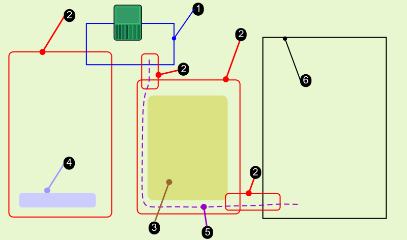
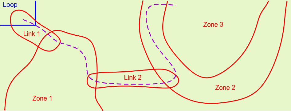
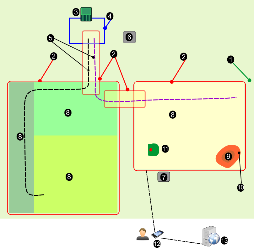
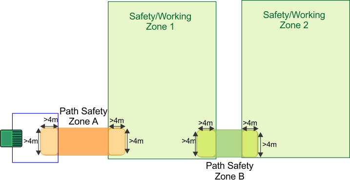
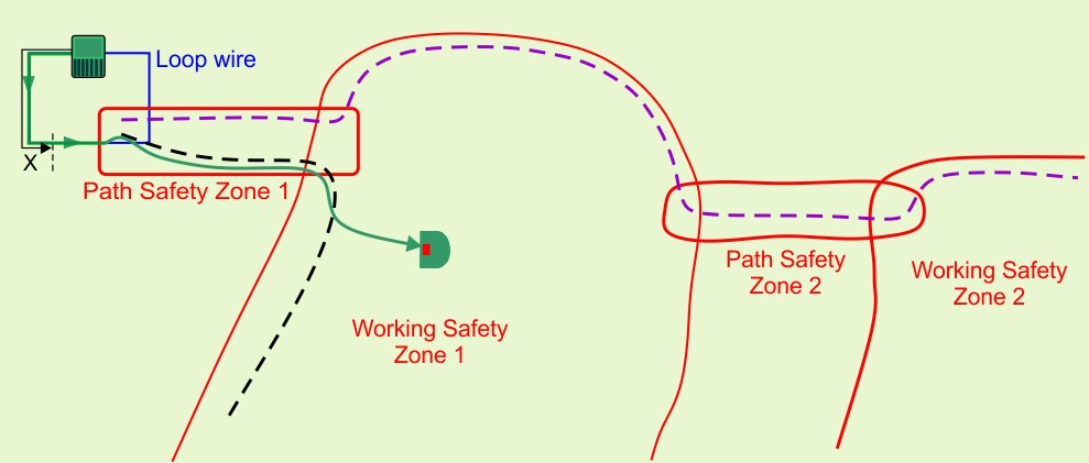
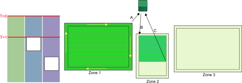
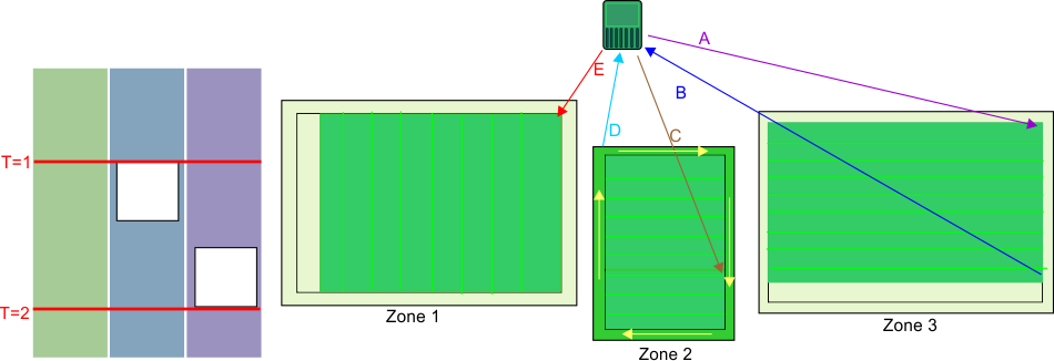
The process 
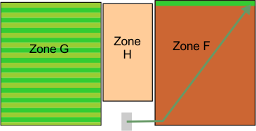
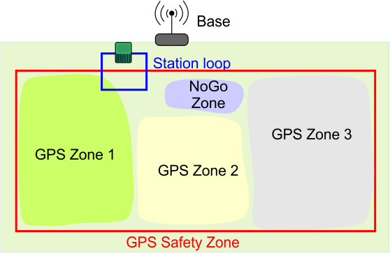
of sequential scheduling is shown in the following figure. Consider the installation setup with three separate zones to be mowed. The defined schedule dictates that zones 2 and 3 are unavailable for certain times of the day.
Graphic
G527683
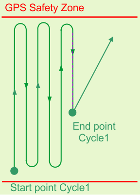
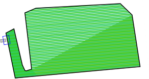
At time T=0, the robot starts mowing zone 1. When the whole area has been mowed, it mows the border and then returns to the station (A). It then 
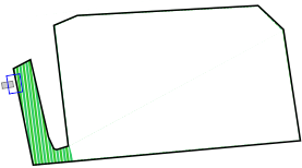
moves to zone 2 (B), and mows until time T=1, at which point, the defined schedule dictates that zone 2 is unavailable. The robot returns to the station (C).
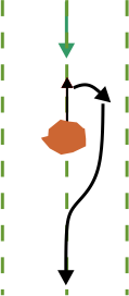
Note: When mowing the border, the robot follows the same direction as was used when the border was discovered.
Graphic
G527684
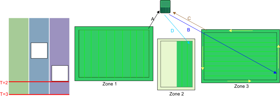
At the time T=1, the robot will move to zone 3 (A) and mow there until the schedule dictates that zone 3 is unavailable. The robot will return to the station (B) and then return to finish mowing zone 2 (C). When the area has been mowed, it will mow the border 
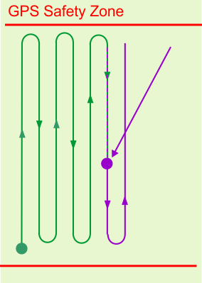
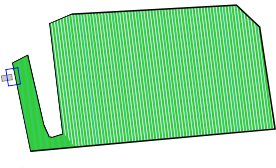
before returning to a station (D). Since zone 3 is still unavailable, 
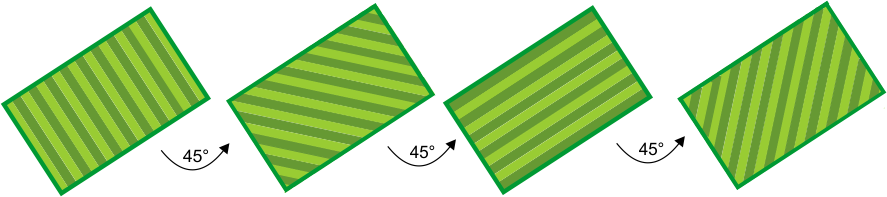
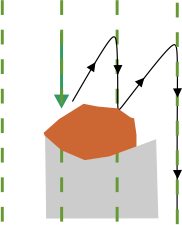
it will move to zone 1 and start mowing in a new direction (E).
At time T=2, zone 1 is not complete, when zone 3 becomes available.
Graphic
G527685
At time T=2, the robot will complete mowing zone 1 and then mow the border before returning to the station (A). It will then return to zone 3 (B) and complete mowing the zone and the border. It will return to the station (C) and then start mowing zone 2 in a new direction (D).
Note: It is strongly recommended to use sequential scheduling. If it is not used, it is necessary to define the percent of time to be spent working in a particular zone and to specify explicitly the number of times per week that the border is to be mowed.
Pattern Working with Defined Percentage Times
When working in pattern mode, the robot will preferentially complete the work in one zone before moving onto another, overriding the allotted percentage times.
Consider the situation where there are three zones:
  • Zone G which has a percentage time of 40%
  • Zone H which has a percentage time of 20%
  • Zone F which has a percentage time of 40%
Graphic
G527686
The robot works in Zone G, until the cycle ends when it needs to return to the station to charge. The work in Zone G is not complete
Graphic
G527687
When the robot resumes working, it will ignore the percentage times allotted and return to Zone G to complete the pattern. When this pattern is complete, it will return to the station and a new cycle will begin.
Graphic
G527688
The robot will now start work on a new zone.
It will start working in Zone F which has a higher percentage of time allotted. A new cycle is started.

Avoiding Obstacles when Mowing

This section describes how the robot deals with small obstacles within the working area. Larger, permanent, and hazardous obstacles have to be avoided by excluding them in the definition of the GPS Safety zone or through the use of NoGo zones.
When mowing normally, the robot moves at a speed of about 1 m/s, 3.5 km/h (3.3 ft/s, 2.2 mph). In areas where the grass is longer, the robot will automatically adapt its mowing mode by slowing down.
The robot can detect an obstacle (permanent or transitory) through a set of sonar sensors. Detection causes the robot to slow down and gently touch the obstacle, as indicated by the pressure sensors on the bumper.
When the robot detects an obstacle when working in pattern mode, it will move backwards and try to navigate around it using small changes in angle. If this is successful, it will continue along the path it was following.
Graphic
G527689
If this is not successful, it will move backwards and then to the next mowing lane, and continuing doing this until it has passed the obstacle.
Graphic
G527690
This means that there is a risk of areas behind the obstacles not being mowed. However, since the direction of mowing changes with each cycle, this may well be remedied on subsequent cycles.

Mowing the Border

When the robot is mowing, the pattern does not reach to the very edge of the working area. It is therefore important to configure the robot to mow the border.
Graphic
G527691
X=21 cm (8.3 inches)
Y=36 cm (14.2 inches)
Each row in the pattern extends to the point where the robot's smartbox tracking device reaches a distance of 0.25 m (9.8 in) from the GPS Safety zone border. The area that is mowed is contained within the GPS border.
The border is only mowed in 1 direction; corresponding to the direction in which the GPS safety border was discovered.
The preferred method of mowing the border is to implement sequential scheduling. In this case the border will be mowed automatically each time the robot completes mowing the working area.
Note: It is strongly recommended that you use sequential sequencing.
If sequential scheduling is not being used, the robot must be configured to mow the border at least 2 times per week.
Note: Border mode is not available for No-Go zones.

Returning to the Station

The robot returns to the station:
  • When the battery needs charging
  • When the schedule dictates it
  • When a command has been issued either from the robot's interface, the web portal or the app
The manner in which the robot returns to the station depends on whether the working area is connected directly to the loop or whether paths are used to link working areas.
Returning to the Station Directly From the Working Area
This situation is most likely to occur in those installations where there is a single working safety area that overlaps directly with the loop wire.
Graphic
G527693
A GPS return point must be located inside the area where the loop and the GPS Safety Zone intersect.
When the robot needs to return to the station it will stop and calculate a route toward the GPS return point. When it detects that it has crossed the loop wire, it turns and follows the loop track wire until it reaches the station.
Returning to the Station Using Paths
Paths are used to enable navigation between different working zones.
Graphic
G527695
When the robot needs to return to the station, it will stop and calculate a route to the nearest position on a path. It is recommended to make the paths extend well into the working zone to facilitate a short route back to a path to return to the station.
It will follow the path using a random offset from the actual path to avoid tracks in the grass. When the robot senses it has entered the station loop wire, it will turn and follow this wire to reach the station. One path (at least) must overlap with the station loop wire.


4G RTK Use Cases
 

A station loop is required for the robot to access the station. At least one GPS safety zone must be connected to the station loop.
Note: For a 4G RTK installation, the GPS signal level of 2 must be available if working zones and NoGo zones are to be accepted.

One GPS Safety Zone

Graphic
G527727
  • The site is open. No trees are restricting the view between the robots, the base, and the satellites.
  • The GPS signal level is 2 over the entire site.
  • The base can be mounted at a height of 4 m (13.1 ft) on a building.
  • The GPS Safety Zone intersects the station loop wire by at least 4 m x 4 m (13 ft x 13 ft). The loop is set as the neighboring parcel to the safety zone.

Two GPS Safety Zones Connected to the Loop

Graphic
G527728
  • Two GPS safety zones are defined, each of which intersect with the station loop by 4 m x 4 m (13 ft x 13 ft). In both cases, the loop must be set as the neighboring parcel to the safety zones.
  • If Wi-Fi is being used for the corrections, it may be necessary to use a repeater.

Two Safety Zones Connected by Paths

Graphic
G527729
  • In addition to the two GPS Safety Zones an additional GPS Safety Zone is created for the GPS Path. This zone connects to the loop with an overlap of more than 4 m x 4 m (13 ft x 13 ft).
  • The path zone intersects with both of the working zones.
  • Paths are created to enable the robot to access both of the working zones.
  • The paths extend well into the working zones. This aids the robot to navigate back to the station.
  • If Wi-Fi is being used for the corrections, it may be necessary to use a repeater.

One Safety Zone, Three GPS Working Zones and One NoGo Zone

Graphic
G527730
  • One GPS Safety Zone encompasses the entire working area.
  • The GPS Safety Zone intersects the station loop wire by at least 4 m x 4 m (13 ft x 13 ft).
  • Three GPS working zones have been defined within the safety zone, to optimize the working schedule of the robot. These do not need to intersect with the station loop wire.
  • One NoGo zone has been defined. This must be at least 5 m (16.4 ft) from the border of the Safety Zone.

Widely Separate Working Zones Connected by Paths

Graphic
G527731
  • Three separate working areas can be connected by paths.
  • The paths are contained in additional safety zones.
  • One path passes through several GPS zones.
  • The paths extend into the working zone to facilitate the return to station from wherever the robot finds itself when it needs to return to the station.

Safety Zone Containing a Narrow Passage

Graphic
G538566
In this example, the safety zone contains a passage where the distance between neighboring sections of the safety zone border is less than 5 m (16.4 ft). This arrangement can pose problems and the configuration shown in the following figure should be adopted instead. In this configuration, two separate zones have been defined to avoid having neighboring sections that are too close.
Graphic
G527733

Paths Connecting GPS and Wired Working Zones

Graphic
G527734
Paths can be used to connect GPS working zones and wired parcels. A peripheral wire may be necessary in those situations where the GPS signal level is less than 2.


Troubleshooting
 

During a 4G RTK installation where there is no peripheral wire, the safety of the robot to operate only within its Safety Zone is critical. There are a number of configuration parameters used in the installation which are monitored. If any of these are modified, an error is generated and the robot will stop working.
These critical parameters are:
When a new mission is launched, any changes are detected automatically and the robot will not start the mission. The cause of the problem can be seen on the 4G RTK SUMMARY screen on the robot's UI. This should appear automatically, but can be viewed by selecting Technician's menu (9) > Infrastructure > 4G RTK Summary.
For details on all the messages that appear on this screen, refer to your Technical Manual.

Troubleshooting RTK GPS Installations

This procedure is used to identify the problem when the GPS signal quality is too low. Signal quality levels can be seen by using Technician's menu (9) > GPS RTK. This procedure consists of a number of stages which should be carried out in order.
Verifying the RTK Base Station GNSS Connection
Note: After each action, always wait a few minutes to verify if GPS signal quality has increased to RTK quality level > 1.2.
Graphic
G527792
Verifying the Robot GNSS Connection
Note: After each action, always wait a few minutes to verify if GPS signal quality has increased to RTK quality level > 1.2.
Graphic
G527793
Verifying the Robot to RTK Base Station Wi-Fi Connection
Note: After each action, always wait a few minutes to verify if GPS signal quality has increased to RTK quality level > 1.2.
Graphic
G527794

Appendices

Inactive State
A condition may arise which causes the robot to stop its autonomous mowing mission and enter an inactive state. Reasons for this could be:
  • The robot has encountered a problem and has issued an alarm.
  • The mission has been manually stopped.
In both these situations there are mechanisms for managing the power consumption of the robot.
Alarm
Graphic
G527797
When the robot encounters a problem it will register an alarm, which will eventually require manual intervention.
If the alarm has not been cleared after 15 minutes, the robot will enter sleep mode. In this state the robot will reduce its power consumption, by shutting down everything apart from the modem.
Note: Sleep mode will only be enabled if the robot has been switched on for more than one hour.
It will continue in sleep mode for 2 days, or until the battery reaches a very low level, after which it will switch itself OFF.
This will require manual intervention: clear the alarm and resume the autonomous work mode, or push the robot to a charging station to charge the battery.
Mission Stopped
Graphic
G527798
In this case, the robot will enter into an idle state. By default, after 15 minutes of being idle, the robot will enter the sleep mode described above, in which the power consumption is reduced to a minimum. It will continue in sleep mode for 2 days, or until the battery reaches a very low level, after which it will switch itself OFF.
Before resuming working, the robot will perform a self test, to check the integrity of the entire system (including electronics, sensors, mechanics and software).
  • If the result of the self test is successful, the robot will resume the autonomous working state.
  • If the result of the self test is not successful, the robot will register an alarm, which will require and intervention.