Safety
Safety and Instructional Decals
 |
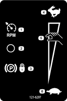
Safety decals and instructions are easily visible to the operator and are located near any area of potential danger. Replace any decal that is damaged or missing. |

Installation
Preparing to Install the Kit
-
Park the machine on a level surface.
-
Engage the parking brake.
-
For machine models with a utility bed, perform the following:
-
Remove the bed from the vehicle. Refer to the vehicle Operator’s Manual for the removal procedure.
-
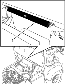
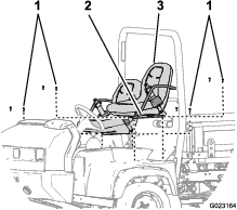
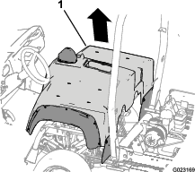
Remove the bed support from the storage brackets on the back of the ROPS panel (Figure 1).
-
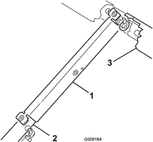
Push the bed support onto the cylinder rod, ensuring that the support end tabs rest on the end of the cylinder barrel, and on the cylinder-rod end (Figure 2).
-
-
Shut off the engine and remove the key.
-
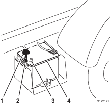
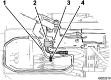
Disconnect the battery as follows:
-
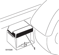
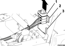
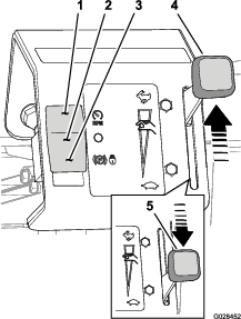
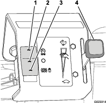
Squeeze the battery cover to release the tabs from the battery base (Figure 3).
-
Remove the battery cover from the battery base (Figure 3).
-
Remove the terminal of the positive battery cable from the battery post (Figure 4).
Note: Ensure that the terminal positive battery cable does not touch the battery post.
-
Removing the Hood
-
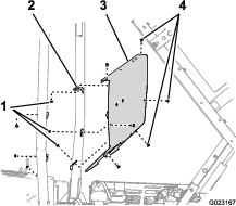
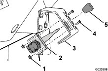
While grasping the hood in the headlight openings, lift up on the hood to release the lower mounting tabs from the frame slots (Figure 5).
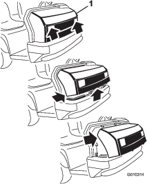
-
Pivot the bottom of the hood upward until the top mounting tabs can be pulled from the frame slots (Figure 5).
-
Pivot the top of hood forward and unplug the wire connectors from the headlights (Figure 5).
-
Remove the hood.
Removing the Center Console Panel and Seats
-
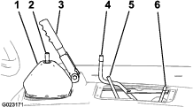
Unscrew and remove all knobs from console levers and from the gear shift lever (Figure 6).
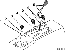
-
Remove the jam nut from the gear shift lever (Figure 6).
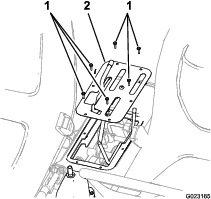
-
Remove the 6 screws securing the outside edge of the cover plate of the center console to the chassis and remove the cover plate (Figure 7).
-
Remove the 8 socket-head bolts that secure the seat rails of the seat to the chassis and remove the seats (Figure 8).
Removing the Coolant Tank, ROPS Shield, and Seat Shroud
Removing the Coolant Tank
-
Lift the coolant tank up and out of the support bracket on the back of the ROPS shield (Figure 9).
-
Set the coolant tank upright onto the engine/chassis.
Removing the ROPS Panel
Installing the Parking-Brake Switch
Parts needed for this procedure:
| Parking-brake switch | 1 |
| Hex-washer head screw(10–24 x 1/2 inch) | 2 |
-
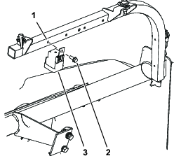
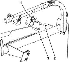
Move the lower-dust boot for the gear selector away from the left side of the parking brake assembly (Figure 13).
-
Align the holes in the parking-brake switch with the holes in the left side of the parking brake (Figure 13).
-
Secure the switch to the brake with the 2 hex-washer head screws (Figure 13).
Installing the Relays
Parts needed for this procedure:
| Relay | 3 |
| Hex-washer head bolt (1/4 x 5/8 inch) | 2 |
-
Install the relay (single location) to the dash-support tube with the bolt (1/4 x 5/8 inch) at the pre-drilled hole on the left (Figure 14).
-
Align the 2 relays back-to-back (Figure 15).
-
Secure the 2 relays to the dash-support tube with the bolt (1/4 x 5/8 inch) in the pre-drilled hole on the right (Figure 15).
Installing the Hand-Throttle Bracket
Parts needed for this procedure:
| Hand throttle bracket | 1 |
| Flange bolt (5/16 x 1 inch) | 4 |
| Flange nut (5/16 inch) | 4 |
Installing the Hand Throttle Bracket
-
Remove the 3 flange bolts and 3 flange nuts that secure the dash panel at the lower center location to the dash support bracket (Figure 16).
Note: Discard the bolts and nuts.
-
Align the holes in the hand-throttle bracket with the holes in the dash panel (Figure 16).
-
Secure the hand-throttle bracket to the dash panel with the 3 flange bolts (5/16 x 1 inch) and 3 flange nuts (Figure 17).
Installing the Hand Throttle and Mode Switch
Parts needed for this procedure:
| Hand throttle | 1 |
| Bolt (10–24 x 5/8 inch) | 2 |
| Serrated nut (10–32) | 2 |
| Mode switch | 1 |
Installing the Hand Throttle
-
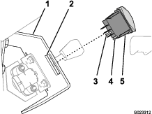
Remove the knob (if it is installed) from the lever of the hand throttle (Figure 18).
-
Align the lever hand throttle to the slot in the hand-throttle bracket, and align the holes in the mounting bracket that is attached to the hand throttle to the hand-throttle bracket (Figure 18).
-
Secure the hand throttle to the hand-throttle bracket with the 2 bolts (10–32 x 5/8) and 2 nuts (Figure 18).
Installing the Wire Harness
Parts needed for this procedure:
| Wire harness | 1 |
| Cable tie | 5 |
Connecting to the Main Harness Interconnections
-
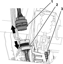
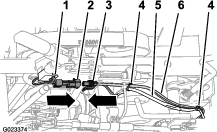
At the front of the machine and adjacent to the fuse block, locate the 31-pin and 31-socket connectors for the front and rear wire harnesses for the machine (Figure 20).
-
Disconnect the 31-pin and 31-socket connectors for the front and rear wire harnesses (Figure 20).
-
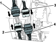
Locate the 31-pin and 31-socket connectors located on the throttle kit harness (Figure 21).
-
Connect the 31-pin connector of the throttle kit harness to the 31-socket connector for the front wire harness of the machine (Figure 21).
-
Connect the 31-socket connector for the throttle kit harness to the 31-pin connector for the rear wire harness of the machine (Figure 21).
Routing the Harness and Connecting the Relay Connectors
-
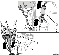
Route the branch of the wire harness with the 3 connectors with 5 sockets each (Figure 22) up to the relays that you installed in Installing the Relays.
-
Connect the 5-socket connectors to the relays (Figure 22).
Note: The relationship between relays and the 5-socket connectors is arbitrary.
-
Remove the resistor from the 6-pin connector for the hand throttle up circuit (Figure 22).
Note: Retain the resistor and install it in the 6-pin connector if the hand throttle kit is removed from the machine.
-
Connect the 6-pin connector for the hand throttle pull-up circuit of the machine harness to the 6-socket connector of the hand throttle pull-up circuit of the hand-throttle harness (Figure 22).
Routing the Harness and Connecting the Hand Throttle and Mode Switch
-
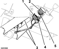
Route the branch of the throttle kit harness between the vertical flanges of the dash support and back toward the hand throttle and mode switch (Figure 23).
-
Connect the 3-socket connector of the throttle kit harness to the connector of the hand throttle (Figure 23).
-
Connect the 8-socket connector of the throttle kit harness to the connector of the mode switch (Figure 23).
Routing the Wire Harness
-
Route the branch of the wire harness of the kit with the 2-pin connector for the parking-brake switch down from the main harness interconnections that you connected in steps 5 and 6 of Connecting to the Main Harness Interconnections and along the rear-wire harness for the machine (Figure 21).
-
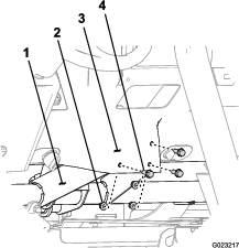
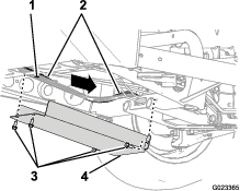
Remove the 4 bolts that secure the lower cover to the machine (Figure 24).
-
Route the wire harness of the kit along the rear main harness of the machine and rearward over the cross channel of the frame as shown in Figure 24.
-
Install the lower cover with the 4 bolts that you removed in step 2 (Figure 24).
-
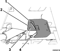
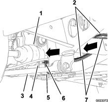
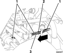
Continue routing the wire harness of the kit along the lower-frame tube and then up behind the upper-control arm and the rear-support channel for the seat (Figure 25, Figure 26, and Figure 27).
Note: The wire harness of the kit will follow the rear main harness of the machine.
-
Secure the wire harness of the kit to the rear-main harness with cable ties at the 2 locations shown in Figure 26 and Figure 27.
-
Secure the wire harness of the kit to the lower-frame tube with a cable tie at the location shown in Figure 25.
Connecting the Harness to the Parking-Brake Switch
-
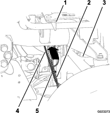
Route the branch of the wire harness for the kit with the 2-pin connector forward to the parking-brake switch (Figure 28) that you installed in Installing the Parking-Brake Switch.
-
Connect the 2-pin socket connector of the wire harness of the kit to the 2-pin connector of the wire harness of the parking-brake switch (Figure 28).
-
Secure the wire harness of the kit to the rear-main harness at the 2 location shown in Figure 28.
Installing the Seat Shroud, ROPS Shield, and Coolant Tank
Installing the Seat Shroud
-
Align the opening in the seat shroud for the parking brake with the parking brake handle.
-
Align the hole in the gear selector boot with the rod for the gear selector.
-
Align the opening in the seat shroud for the rods for the lift bed control, high-low range shifter, and the differential lock.
-
Lower the seat shroud down.
-
Align the holes in the shroud for the seat mounting with the seat support brackets of the chassis.
Installing the ROPS Shield
-
Align the holes in the ROPS shield with the hole in the brackets on the rollbar (Figure 10).
-
Secure the ROPS shield to the rollbar with the 6 carriage bolts and 6 nuts (Figure 10) that you removed in step 1 of Removing the ROPS Panel.
Installing the Center Console Panel and Seats
-
Align the holes in the seat rails with the holes in the shroud for the seat mounting positions (Figure 8).
-
Secure the seats to the chassis with the 8 socket-head bolts (Figure 8) that you removed in step 4 of Removing the Center Console Panel and Seats.
-
Torque the socket head bolts to 255 to 254 N∙m (175 to 225 in-lb).
-
Align the center console panel over the control rods at the center console (Figure 7).
-
Secure the pane with the 6 screws (Figure 6) that you removed in step 3 of Removing the Center Console Panel and Seats.
-
Thread the jam nut onto the gear shift lever and thread the shift knob on the shift lever (Figure 6).
-
Align the shift pattern on the knob and then tighten the jam nut.
-
Thread the 3 control knobs that you removed in step 1 of Removing the Center Console Panel and Seats onto the rods for the hydraulic bed lift, differential lock, and the high-low range shifter (Figure 6).
Connecting the Battery
Lowering the Bed
Installing the Hood
-
Align the bottom of the hood to the top of the bumper (Figure 5).
-
Connect the lights.
-
Insert the top mounting tabs into the frame slots (Figure 5).
-
Insert the lower mounting tabs into the pockets in the bumper (Figure 5).
-
Ensure that the hood is fully engaged in the top, sides, and bottom grooves (Figure 5).
Testing the Hand Throttle Kit
Testing the Accessory Mode
-
Move the machine to a clear level surface.
-
Move the hand throttle to the SLOW position (Figure 29).
-
Press the mode switch down to the throttle-lock position (Figure 29).
-
Set the parking brake, place the gear selector in the NEUTRAL position, and start the machine.
-
Move the hand throttle toward the FAST position (Figure 29).
Note: The engine speed should rise.
-
Move the hand throttle to the SLOW position (Figure 29).
-
Place your foot on the service brake.
-
Release the parking brake.
-
Move the hand throttle toward the FAST position (Figure 29).
Note: The engine speed should remain at idle.
-
Set the parking brake and shut off the machine.
Testing the Normal Ground-Speed Mode
-
Move the hand throttle to the SLOW position (Figure 29).
-
Press the mode switch up to the OFF position (Figure 29).
-
Set the parking brake, place the gear selector in the NEUTRAL position, and start the machine.
-
Press on the throttle pedal partially.
Note: The engine speed should rise.
-
Release the throttle pedal.
-
Move the hand throttle toward the FAST position (Figure 29).
Note: The engine speed should remain at idle.
-
Shut off the machine.
Testing the Limit Ground-Speed Mode
-
Move the hand throttle to the SLOW position (Figure 29).
-
Press the mode switch up to the limit ground-speed position (Figure 29).
-
Set the parking brake, place the gear selector in the NEUTRAL position, and start the machine.
-
Press down the throttle pedal partially.
Note: The engine speed should remain at idle.
-
While pressing the throttle pedal, move the hand throttle toward the FAST position (Figure 29).
Note: The engine speed should rise.
Product Overview
Hand Throttle
The hand throttle is used in conjunction with the mode switch to limit the maximum engine speed or set a fixed engine speed (Figure 30).
Mode Switch
The mode switch (Figure 30) is used to control the function of the hand throttle for the following operations:
-
Limit Ground-speed Mode position—Use this switch position to limit the maximum travel speed of the machine while performing machine-based operations.
-
Off position—Use this switch position for normal control of the machines ground speed.
-
Accessory Mode position—Use this switch position to control the engine speed when the machine is used to power accessory equipment in a stationary position.
Operation
Using the Limit Ground-Speed Mode
Setting the maximum engine speed
-
Move the machine to a clear level surface.
-
Move the hand throttle to the Slow position (Figure 30).
-
Press the mode switch up to the limit ground-speed position (Figure 30).
-
Move the gear selector to the gear for the desired ground speed.
-
Fully press down the throttle pedal.
-
Move the hand throttle toward the fast position (Figure 30) until the desired ground speed is reached.
-
Release the throttle pedal.
-
Perform the ground speed-limited task, such as applying topdressing material.
Note: To drive the machine at the maximum ground speed limit that you set, fully press down on the throttle pedal.
Using the Normal Ground-Speed Mode
Using the Accessory Mode
-
Move the machine to the work site.
-
Ensure that the gear selector is in the NEUTRAL position and the parking brake is set.
-
Press the mode switch down to the throttle-lock position (Figure 30).
-
Move the hand throttle to the desired engine speed (Figure 30).
-
Perform the accessory based task, such as using the tank mixing or hand sprayer operations.
-
Move the hand throttle to the SLOW position (Figure 30).
-
Press the mode switch up to the OFF position (Figure 30).
Troubleshooting
| Problem | Possible Cause | Corrective Action |
|---|---|---|
| The engine is not controlled by the hand throttle when in the accessory mode. |
|
|
| The engine power is too low for the accessory. |
|
|
| The engine power is too high for the accessory. |
|
|
| Problem | Possible Cause | Corrective Action |
|---|---|---|
| The machine does not accelerate to the desired speed with the throttle pedal. |
|
|
| The ground speed of the machine is too slow for the speed-limited task. |
|
|
| The ground speed of the machine is too fast for the speed-limited task. |
|
|