Disclaimers and Regulatory Information
This product complies with
all relevant European directives; for details, please see the separate
product specific Declaration of Conformity (DOC)
sheet.
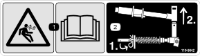
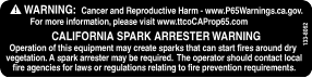
It is a violation of California
Public Resource Code Section 4442 or 4443 to use or operate the engine
on any forest-covered, brush-covered, or grass-covered
land unless the engine is equipped with a spark arrester, as defined
in Section 4442, maintained in effective working
order, or the engine is constructed, equipped, and maintained for
the prevention of fire.
The enclosed engine owner's manual
is supplied for information regarding the US Environmental Protection
Agency (EPA) and the California Emission Control
Regulation of emission systems, maintenance, and warranty. Replacements
may be ordered through the engine manufacturer.
 |
| CALIFORNIA |
| Proposition 65 |
| Diesel engine exhaust and some of its constituents are known to the State of California to cause cancer, birth defects, and other reproductive harm. |
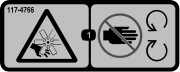
| Battery posts, terminals, and related accessories contain lead and lead compounds, chemicals known to the State of California to cause cancer and reproductive harm. Wash hands after handling. |
| Use of this product may cause exposure to chemicals known to the State of California to cause cancer, birth defects, or other reproductive harm. |
Electromagnetic Compatibility Certification
If this machine is equipped with
a telematics device, refer to your authorized Toro distributor for
instructions to activate the device.
| Domestic: This device complies with FCC
Rules Part 15. Operation is subject to the following two conditions:
(1) This device may not cause
harmful interference and (2) this device must accept any interference
that may be received, including interference that
may cause undesirable operation. |
| FCC ID: APV-3640LB IC: 5843C-3640LB |
| This equipment has been tested
and found to comply within the limits for a Class B digital device,
pursuant to part 15 of the
FCC Rules. These limits are designed to provide reasonable protection
against harmful interference in a residential installation.
This equipment generates, uses, and
can radiate radio frequency energy and, if not installed and used
in accordance with the instructions,
may cause harmful interference to radio communications. However, there
is no guarantee that interference will
not occur in a particular installation. If this equipment
does cause harmful interference to radio or television reception,
which can be determined by
turning the equipment off and on, the user is encouraged to try to
connect the interference by
one or more of the following measures:
|
| Argentina
|
New Zealand |
 |
 |
| Australia
|
South Korea |
 |
 |
| Morocco
|
| AGREE PAR L’ANRT MAROC
Numéro
d’agrément: MR00004789ANRT20024 Date d’agrément: 11/4/2024 |
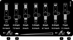
Fuel