Installation
Note: Use this kit for adapting the Rear Roller Brush (Model 04650) attachment only when it is not used in conjunction with the Universal Groomer (Model 04648).
Note: Left adapters are only needed on Models 04358 and 04384.
Note: Determine the left and right sides of the machine from the normal operating position.
Preparing the Machine
-
Park the machine on a level surface, disengage the cutting units, and engage the parking brake.
-
Shut off the engine, remove the key, and wait for all movement to stop.
-
If the cutting unit is installed, remove the cutting unit from the traction unit; refer to the Operator's Manual for the traction unit.
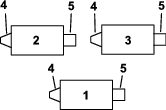
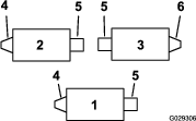
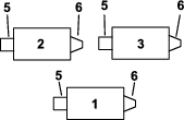
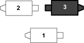
Determining the Orientation of the Roller Brushes
Use the following figures to determine the appropriate position of the roller brushes.
Removing the Counterweight and Plug(All Machines)
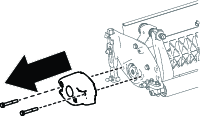

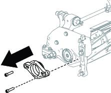
Removing the Motor Mount
-
Remove the 2 bolts securing the motor mount to the side plate of the cutting unit, and remove the motor mount.
-
Install the motor mount where you removed the weight.
Removing the Drive Spline (All Machines)
Warning
The cutting reel blades are sharp and capable of amputating hands and feet.
-
Keep your hands and feet outside of the reel.
-
Ensure that the reel is restrained before servicing it.
-
Identify the drive spline to be removed.
Note: You will remove the drive spline from the roller brush drive assembly side of the cutting unit; refer to Determining the Orientation of the Roller Brushes.
-
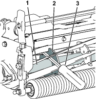
Restrain the reel:
-
Tip up the cutting unit so that you access the bottom of the reel.
-
Insert a long-handled pry bar (recommended 3/8 x 12 inches with a screwdriver handle) through the bottom of the cutting reel, closest to the side of the cutting unit that you will be torquing.
-
Place the pry bar against the weld side of the reel support plate.
Note: Insert the pry bar between the top of the reel shaft and the backs of the reel blades so that the reel will not move.
Important: Do not contact the cutting edge of any blades with the pry bar; this may damage the cutting edge and/or cause a high blade.
Important: The insert on the left side of the cutting unit has left-hand threads. The insert on the right side of the cutting unit has right-hand threads.
-
Rest the handle of the pry bar against the roller.
-
Complete the removal of the drive spline insert while ensuring that the pry bar stays in place, then remove the pry bar.
-
Lower the cutting unit to rest on the rollers.
-
-
Use a dry, clean cloth to clean the internal threads on the end of the cutting unit.
Installing the Adapter(s)
Parts needed for this procedure:
| Right adapter | 1 |
| O-ring | 1 |
| Adapter housing | 1 |
| Bolt (5/16 x 5/8 inch) | 1 |
| Left adapter (for Models 04358 and 04384 only) | 1 |
| Washer (for Models 04358 and 04384 only) | 1 |
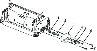
Installing the Right Adapter
-
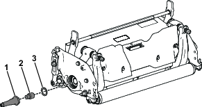
Apply thread-locking compound on the internal threads of the driveshaft. Torque the adapter into the driveshaft to 129 to 142 N∙m (95 to 105 ft-lb) (Figure 9).
Important: The insert on the left side of the cutting unit has left-hand threads. The insert on the right side of the cutting unit has right-hand threads.
Note: The adapter for the left side of the cutting unit is black. The adapter for the right side of the cutting unit is silver.
-
Apply thread-locking compound on the internal threads of the reel shaft.
-
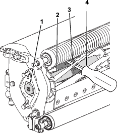
Restrain the reel:
-
Insert a long-handled pry bar (recommended 3/8 x 12 inches with a screwdriver handle) through the front of the cutting reel, closest to the side of the cutting unit that you will be torquing (Figure 10).
-
Place the pry bar against the weld side of the reel support plate (Figure 12).
Note: Insert the pry bar between the top of the reel shaft and the backs of the reel blades so that the reel will not move.
Important: Do not contact the cutting edge of any blades with the pry bar; this may damage the cutting edge or cause a high blade.
Important: The insert on the left side of the cutting unit has left-hand threads. The insert on the right side of the cutting unit has right-hand threads.
-
Rest the handle of the pry bar against the roller.
-
Follow the installation instructions for the threaded inserts to install them while keeping the pry bar in place. Torque the insert as recommended.
-
Remove the pry bar.
-
-
Install the adapter assembly into the reel while ensuring that the pry bar stays in place, and torque it to 115 to 129 N∙m (85 to 95 ft-lb).
-
Remove the pry bar.
-
Install the previously removed weight with the 2 corresponding bolts (5/16 x 2-1/4 inches); refer to Figure 9.
-
Install the O-ring and adapter housing on the weight. Secure it with the bolt (5/16 x 5/8 inch); refer to Figure 9.
Installing the Left Adapter
-
Apply thread-locking compound on the internal threads of the driveshaft. Torque the adapter into the driveshaft to 129 to 142 N∙m (95 to 105 ft-lb) (Figure 9).
Important: The insert on the left side of the cutting unit has left-hand threads. The insert on the right side of the cutting unit has right-hand threads.
Note: The adapter for the left side of the cutting unit is black. The adapter for the right side of the cutting unit is silver.
-
Apply thread-locking compound on the internal threads of the reel shaft.
-
Restrain the reel:
-
Insert a long-handled pry bar (recommended 3/8 x 12 inches with a screwdriver handle) through the front of the cutting reel, closest to the side of the cutting unit that you will be torquing (Figure 12)
-
Place the pry bar against the weld side of the reel support plate (Figure 12).
Note: Insert the pry bar between the top of the reel shaft and the backs of the reel blades so that the reel will not move.
Important: Do not contact the cutting edge of any blades with the pry bar; this may damage the cutting edge or cause a high blade.
-
Rest the handle of the pry bar against the roller.
-
-
Install the washer and adapter assembly into the reel and torque it to 115 to 129 N∙m (85 to 95 ft-lb); refer to Figure 11.
-
Remove the pry bar.
-
Install the previously removed weight with the 2 corresponding bolts (5/16 x 2-1/4 inches); refer to Figure 9.
-
Install the O-ring and adapter housing on the weight. Secure it with the bolt (5/16 x 5/8 inch); refer to Figure 9.