


Maintenance
Note: Determine the left and right sides of the machine from the normal operating position.
Maintenance Safety
-
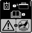
Park machine on level ground, disengage drives, set parking brake, stop engine, and remove key. Wait for all moving parts to stop before leaving the operator’s position. Allow the machine to cool before servicing, adjusting, fueling, cleaning, or storing.
-
If you leave the key in the switch, someone could accidently start the engine and seriously injure you or other bystanders. Remove the key from the switch before you perform any maintenance.
-
Never allow untrained personnel to service machine.
-
Disconnect battery or remove spark plug wire before making any repairs. Disconnect the negative terminal first and the positive last. Reconnect positive first and negative last.
-
Keep all guards, shields, switches, and all safety devices in place and in proper working condition. Frequently check for worn or deteriorating components and replace them with genuine Exmark parts when necessary.
Warning
Removal or modification of original equipment, parts and/or accessories may alter the warranty, controllability, and safety of the machine. Unauthorized modifications to the original equipment or failure to use original Exmark parts could lead to serious injury or death. Unauthorized changes to the machine, engine, fuel or venting system, may violate applicable safety standards such as: ANSI, OSHA and NFPA and/or government regulations such as EPA and CARB.
Warning
Hydraulic fluid escaping under pressure can penetrate skin and cause injury. Fluid accidentally injected into the skin must be surgically removed within a few hours by a doctor familiar with this form of injury or gangrene may result.
-
If equipped, make sure all hydraulic fluid hoses and lines are in good condition and all hydraulic connections and fittings are tight before applying pressure to hydraulic system.
-
Keep body and hands away from pinhole leaks or nozzles that eject high pressure hydraulic fluid.
-
Use cardboard or paper, not your hands, to find hydraulic leaks.
-
Safely relieve all pressure in the hydraulic system by placing the motion control levers in neutral and shutting off the engine before performing any work on the hydraulic system.
For EFI (Electronic Fuel Injection) Units:
Warning
Fuel system components are under high pressure. The use of improper components can result in system failure, gasoline leakage and possible explosion.
Use only approved fuel lines and fuel filters for high pressure systems.
-
-
Use care when checking blades. Wrap the blade(s) or wear gloves, and use caution when servicing them. Only replace damaged blades. Never straighten or weld them.
-
Do not rely solely on mechanical or hydraulic jacks for support. Use adequate jack stands.
-
Carefully release pressure from components with stored energy.
-
Keep your hands and feet away from moving parts or hot surfaces. If possible, do not make adjustments with the engine running.
-
Keep all parts in good working condition and all hardware tightened, especially the blade-attachment hardware.
Recommended Maintenance Schedule(s)
| Maintenance Service Interval | Maintenance Procedure |
|---|---|
| After the first 5 hours |
|
| After the first 100 hours |
|
| After the first 250 hours |
|
| Before each use or daily |
|
| Every 40 hours |
|
| Every 50 hours |
|
| Every 80 hours |
|
| Every 100 hours |
|
| Every 200 hours |
|
| Every 250 hours |
|
| Every 500 hours |
|
| Yearly |
|
Periodic Maintenance
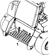
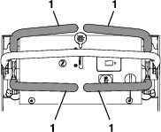
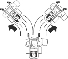
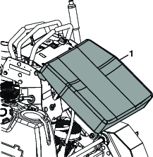
Lift the Thigh Pad for Rear Access
The thigh pad can be removed for easy access to the hydro oil reservoir and pumps.
-
Lift the thigh pad roughly thirty degrees and lift to remove from machine.
-
Perform any maintenance or adjustment on the machine.
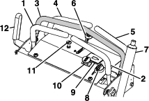
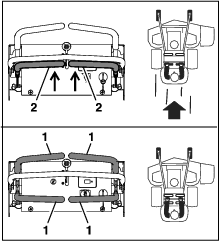
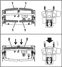
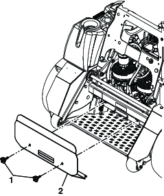
Removing the Rear Guard
-
Remove and retain the thigh pad.
-
Remove and retain the two knobs from the rear guard as shown in Figure 17.
-
Pull the rear guard away from machine.
-
After the maintenance or adjustment is complete, reinstall the rear guard and hand tighten the knobs to secure the guard to the machine.
-
Reinstall the thigh pad.
Engine Maintenance
Important: For Kawasaki and Kohler Engines, refer to the Engine Owner's Manual for additional maintenance procedures.
Engine Safety
Warning
The engine can become very hot, especially the muffler and exhaust components. Touching a hot engine can cause severe burns.
Allow the engine to cool completely before service or making repairs around the engine area.
Do Not change the engine governor setting or overspeed the engine.
Check Engine Oil Level
| Maintenance Service Interval | Maintenance Procedure |
|---|---|
| Before each use or daily |
|
-
Stop engine and wait for all moving parts to stop. Make sure unit is on a level surface.
-
Check with engine cold.
-
Clean area around dipstick. Remove dipstick and wipe oil off. Reinsert the dipstick according to the engine manufacturer's recommendations. Remove the dipstick and read the oil level.
-
If the oil level is low, wipe off the area around the oil fill cap, remove cap and fill to the “FULL” mark on the dipstick. Exmark 4-Cycle Premium Engine Oil is recommended; refer to the Engine Owner's manual for an appropriate API rating and viscosity. Do Not overfill.
Important: Do Not operate the engine with the oil level below the “LOW” (or “ADD”) mark on the dipstick, or over the “FULL” mark.
Check Battery Charge
Allowing batteries to stand for an extended period of time without recharging them will result in reduced performance and service life. To preserve optimum battery performance and life, recharge batteries in storage when the open circuit voltage drops to 12.4 volts.
Note: To prevent damage due to freezing, battery should be fully charged before putting away for winter storage.
Charge batteries in an open well ventilated area, away from spark and flames. Unplug charger before connecting or disconnecting from battery. Wear protective clothing and use insulated tools.
Danger
Charging or jump starting the battery may produce explosive gases. Battery gases can explode causing serious injury.
-
Keep sparks, flames, or cigarettes away from battery.
-
Ventilate when charging or using battery in an enclosed space.
-
Make sure venting path of battery is always open once battery is filled with acid.
-
Always shield eyes and face from battery.
Danger
Battery electrolyte contains sulfuric acid, which is poisonous and can cause severe burns. Swallowing electrolyte can be fatal or if it touches skin can cause severe burns.
-
Wear safety glasses to shield eyes, and rubber gloves to protect skin and clothing when handling electrolyte.
-
Do Not swallow electrolyte.
-
In the event of an accident, flush with water and call a doctor immediately.
Caution
If the ignition is in the “ON” position there is potential for sparks and engagement of components. Sparks could cause an explosion or moving parts could accidentally engage causing personal injury.
Be sure ignition switch is in the “OFF” position before charging the battery.
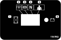
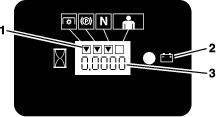
Check the voltage of the battery with a digital voltmeter or with the message display When the ignition is set to the accessory mode, the module will display the battery voltage. If the voltage is less than 12.4 volts, the battery may need to be charged.
Important: Make sure the negative battery cable is disconnected and the battery charger used for charging the battery should have an output of 16 volts and 7 amps or less to avoid damaging the battery (see chart for recommended charger settings). This is especially important on EFI (Electronic Fuel Injection) units. Failure to do so may damage the ECU (Electronic Control Unit).
| Voltage Reading | Percent Charge | Maximum Charger Settings | Charging Interval |
|---|---|---|---|
| 12.6 or greater | 100% | 16 volts/7 amps | No Charging Required |
| 12.4 – 12.6 | 75–100% | 16 volts/7 amps | 30 Minutes |
| 12.2 – 12.4 | 50–75% | 16 volts/7 amps | 1 Hour |
| 12.0–12.2 | 25–50% | 14.4 volts/4 amps | 2 Hours |
| 11.7–12.0 | 0–25% | 14.4 volts/4 amps | 3 Hours |
| 11.7 or less | 0% | 14.4 volts/2 amps | 6 Hours or More |
Important: For EFI units: Unplug the harness from the ECU before performing any welding on the equipment.
Recommended Jump Starting Procedure
-
Check the weak battery for terminal corrosion (white, green, or blue “snow”), it must be cleaned off prior to jump starting. Clean and tighten connections as necessary.
Caution
Corrosion or loose connections can cause unwanted electrical voltage spikes at anytime during the jump starting procedure.
Do Not attempt to jump start with loose or corroded battery terminals or damage to the engine or EFI may occur.
Danger
Jump starting a weak battery that is cracked, frozen, has low electrolyte level, or an open/shorted battery cell, can cause an explosion resulting in serious personal injury.
Do Not jump start a weak battery if these conditions exist.
-
Make sure the booster is a good and fully charged lead acid battery at 12.6 volts or greater. Use properly sized jumper cables (4 to 6 AWG) with short lengths to reduce voltage drop between systems. Make sure the cables are color coded or labeled for the correct polarity.
Caution
Connecting the jumper cables incorrectly (wrong polarity) can immediately damage the electrical and/or EFI system.
Be certain of battery terminal polarity and jumper cable polarity when hooking up batteries.
Note: The following instructions are adapted from the SAE J1494 Rev. Dec. 2001 – Battery Booster Cables – Surface Vehicle Recommended Practice (SAE – Society of Automotive Engineers).
Warning
Batteries contain acid and produce explosive gases.
-
Shield the eyes and face from the batteries at all times.
-
Do Not lean over the batteries.
Note: Be sure the vent caps are tight and level. Place a damp cloth, if available, over any vent caps on both batteries. Be sure the vehicles do not touch and that both electrical systems are off and at the same rated system voltage. These instructions are for negative ground systems only.
-
-
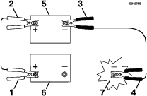
Connect the positive (+) cable to the positive (+) terminal of the discharged battery that is wired to the starter or solenoid as shown in .
-
Connect the other end of the positive cable to the positive terminal of the booster battery.
-
Connect the black negative (–) cable to the other terminal (negative) of the booster battery.
-
MAKE THE FINAL CONNECTION ON THE ENGINE BLOCK OF THE STALLED VEHICLE (NOT TO THE NEGATIVE POST) AWAY FROM THE BATTERY. STAND BACK.
-
Start the vehicle and remove the cables in the reverse order of connection (the engine block (black) connection is the first to disconnect).
Note: A malfunctioning machine battery may cause the charging voltage to exceed 18.5 volts. The engine will turn off if there is a charge above 18.5 volts. Turn the ignition switch off, then on again to reset the engine before restarting the machine.
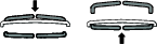
Check Mower Blades
| Maintenance Service Interval | Maintenance Procedure |
|---|---|
| Before each use or daily |
|
-
Stop engine, wait for all moving parts to stop, and remove key. Engage parking brake.
-
Lift deck and secure in raised position as stated in the Clean Grass Build-Up Under Deck section.
-
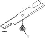
Inspect blades and sharpen or replace as required.
-
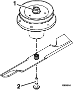
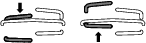
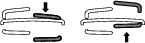
Reinstall the blades (if they were removed) in the following order:
-
Install bushing through blade with bushing flange on bottom (grass) side of blade.
-
Install bushing/blade assembly into spindle.
-
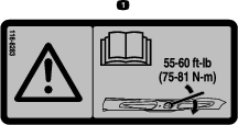
Apply lubricant to threads of blade bolt as needed to prevent seizing. Copper-based anti-seize preferable. Grease acceptable substitute. Install blade bolt finger tight. Place wrench on the top spindle nut then torque the blade bolts to 50-60 ft-lb (68-81 N-m).
Warning
Incorrect installation of the blade or components used to retain the blade can be dangerous. Failure to use all original components and assembled as shown could allow a blade or blade component to be thrown out from under the deck resulting in serious personal injury or death.
Always install the original Exmark blades, blade bushings, and blade bolts as shown.
-
Check Safety Interlock System
Important: It is essential that operator safety mechanisms be connected and in proper operating condition prior to use.
Note: If machine does not pass any of these tests, Do Not operate. Contact an Authorized Service Dealer.
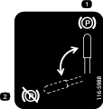
Note: To prevent PTO disengagement on rough terrain, the platform has a 1/2 second time delay before the PTO disengages after the operator leaves the platform.
Check the Normal Engine Starting Chart
| Maintenance Service Interval | Maintenance Procedure |
|---|---|
| Before each use or daily |
|
Note: It is not necessary for the operator to be on the platform to start the engine.
| System | ||||||
| Parking Brake | PTO (Blades) | Motion Control Levers | Operator | Outcome | ||
| State of System | Engaged | Disengaged | In neutral | On platform or off the platform | Starter should crank | |
 |  |  |   |  |
||
| System | ||||||
| Parking Brake | PTO (Blades) | Motion Control Levers | Operator | Outcome | ||
| State of System | Engaged | Up position, but blades disengaged* | In neutral | On platform or off the platform | Starter should crank | |
|  | | | |
||
*Note: The starter will crank with the PTO switch in the “ON” (pulled up) position; however, the system will disengage the PTO and a reset PTO error will occur. Engaging the PTO will require the operator to reset the PTO switch by turning it “OFF” (pushed down) and then turning it “ON”.
Check Engine Starting Circuit Chart
Note: In the Check Engine Starting Circuit Chart, the state of system item that is bold is being checked in each scenario.
| System | ||||||
| Parking Brake | PTO (Blades) | Motion Control Levers | Operator | Outcome | ||
| State of System | Disengaged | Disengaged | In neutral | On platform or off the platform | Starter must not crank | |
 | | | |  |
||
| State of System | Engaged | Disengaged | * Levers not in neutral both levers moved forward or rearward, or either right or left lever moved forward or rearward | On platform or off the platform | Starter must not crank | |
| |    | | |
||
*Note: First disengage the parking brake, move the motion controls out of neutral, re-engage the parking brake, then continue checking the scenario.
Check Engine Starting Circuit Chart—continued
| System | ||||||
| Parking Brake | PTO (Switch) | Motion Control Levers | Operator | Outcome | ||
| State of System | Disengaged | Up position | In neutral | On platform or off the platform | Starter must not crank | |
| | | | |
||
Check Shutdown Circuit Chart
Note: The state of system item(s) that is bold is being checked in each scenario.
| System | ||||||
| State of System | Engine | Parking Brake | PTO (Blades) | Motion Control Levers | Operator | Outcome |
| Running idle (1/3 throttle) | Engaged or Disengaged | Engaged | In neutral | Step off of platform | PTO must begin shutdown within 1 second; engine stays running. | |
 | |  | | |  |
|
Check for Loose Hardware
| Maintenance Service Interval | Maintenance Procedure |
|---|---|
| Before each use or daily |
|
-
Stop engine, wait for all moving parts to stop, and remove key. Engage parking brake.
-
Visually inspect machine for any loose hardware or any other possible problem. Tighten hardware or correct the problem before operating.
Service Air Cleaner
| Maintenance Service Interval | Maintenance Procedure |
|---|---|
| Every 250 hours |
|
| Every 500 hours |
|
-
Stop engine, wait for all moving parts to stop, and remove key. Engage parking brake.
-
See the Engine Owner's Manual for maintenance instructions.
Check Air Filter Assembly (if equipped)
Important: To prevent engine damage, always operate the engine with both air filters and cover installed.
-
When checking or replacing the air filter element, make sure the air filter assembly is installed in the brackets.
-
Position the air cleaner cover so that the breather valve does not interfere with the throttle mechanism.
-
Secure the cover with latches.
Change Engine Oil
| Maintenance Service Interval | Maintenance Procedure |
|---|---|
| After the first 5 hours |
|
| Every 100 hours |
|
-
Stop engine, wait for all moving parts to stop, and remove key. Engage parking brake.
-
Drain oil while engine is warm from operation.
-
The oil drain hose is located on left hand side of engine at the rear. Place pan under machine to catch oil. Remove plug from end of drain hose. Allow oil to drain and replace oil drain plug. Torque plug to 20-24 ft-lb.
-
Replace the oil filter every other oil change. Clean around oil filter and unscrew filter to remove. Before reinstalling new filter, apply a thin coating of Exmark 4–Cycle Premium Engine oil on the surface of the rubber seal. Turn filter clockwise until rubber seal contacts the filter adapter then tighten filter an additional 1/2 to 3/4 turn.
-
Clean around oil fill cap and remove cap. Fill to specified capacity and replace cap.
-
Use oil recommended in the Check Engine Oil Level section. Do Not overfill. Start the engine and check for leaks.
-
Wipe up any spilled oil from engine deck mounting surfaces.
Check Hydraulic Oil Level
| Maintenance Service Interval | Maintenance Procedure |
|---|---|
| Every 40 hours |
|
-
Stop engine and wait for all moving parts to stop, and remove key. Engage parking brake.
-
Clean area around hydraulic reservoir cap and remove cap.
-
X-Series:
-
Wipe the dipstick clean and re-insert the cap back into the hydro. Lightly tighten the cap.
-
Remove the cap again and check the level of the oil on the dipstick. See Figure 22 for oil levels.
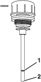
Note: The oil level on the dipstick will be incorrect if the oil is checked when the machine is hot.
Note: The dipstick has a cross-hatched area for hot oil (upper end) and cold oil (lower end). The oil level varies with the temperature of the oil. The upper end of cross-hatching shows the level of oil when it is at 225°F (107°C). The lower end of cross-hatching shows the level of the oil when it is at 75°F (24°C). Fill to the appropriate level depending upon the temperature of the oil. For example: If the oil is about 150° F (65°C), fill to halfway in the cross-hatched area. If the oil is at room temperature (about 75° F (24°C)), fill only to the lower end.
-
-
S-Series:
Oil level should be to the top of the baffle inside the tank.
The baffle is labeled “HOT” and “COLD”. The oil level varies with the temperature of the oil. The “HOT” level shows the level of oil when it is at 225°F (107°C). The “COLD” level shows the level of the oil when it is at 75°F (24°C). Fill to the appropriate level depending upon the temperature of the oil. For example: If the oil is about 150°F (65°C), fill to halfway between the “HOT” and “COLD” levels. If the oil is at room temperature (about 75°F (24°C)), fill only to the “COLD” level.
-
-
If the oil level is below the “ADD” or “COLD” level, add Exmark Premium Hydro Oil. Do Not overfill.
-
Replace hydraulic reservoir cap and tighten until snug. Do Not overtighten.
Check Tire Pressures
| Maintenance Service Interval | Maintenance Procedure |
|---|---|
| Every 50 hours |
|
-
Stop engine, wait for all moving parts to stop, and remove key. Engage parking brake.
-
Check tire pressure in drive tires.
-
Inflate drive tires to 12–14 psi (83–97 kPa).
-
Semi-pneumatic caster tires do not need to be inflated.
Check Condition Of Belts
| Maintenance Service Interval | Maintenance Procedure |
|---|---|
| Every 50 hours |
|
-
Stop engine, wait for all moving parts to stop, and remove key. Engage parking brake.
-
Look on the top side of the cutting deck to check the mower blade drive belt condition.
-
Look under the engine deck to check the pump drive belt condition.
-
Check all idler arms to be sure they pivot freely.
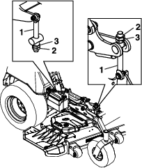
Lubricate Grease Fittings
| Maintenance Service Interval | Maintenance Procedure |
|---|---|
| Yearly |
|
Note: See chart for service intervals.
-
Stop engine, wait for all moving parts to stop, and remove key. Engage parking brake.
-
Lubricate fittings with NLGI grade #2 multi-purpose gun grease.
Refer to the following chart for fitting locations and lubrication schedule.
Lubrication Chart
Lubrication Chart Fitting Locations Initial Pumps Number of Places Service Interval 1. Deck Idler Pivot 1 2 Yearly 2. Front Caster Pivots *0 2 *Yearly 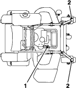
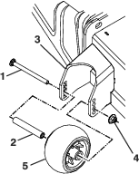
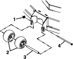
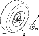
Lubricate Caster Wheel Hubs
-
Stop engine, wait for all moving parts to stop, and remove key. Engage parking brake.
-
Remove caster wheel from caster forks.
-
Remove seal guards from the wheel hub.
-
Remove one of the spacer nuts from the axle assembly in the caster wheel. Note that thread locking adhesive has been applied to lock the spacer nuts to the axle. Remove the axle (with the other spacer nut still assembled to it) from the wheel assembly.
-
Pry out seals, and inspect bearings for wear or damage and replace if necessary.
-
Pack the bearings with a NLGI grade #1 multi-purpose grease.
-
Insert one bearing, one new seal into the wheel.
Note: Seals (Exmark P/N 103-0063) must be replaced.
-
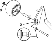
If the axle assembly has had both spacer nuts removed (or broken loose), apply a thread locking adhesive to one spacer nut and thread onto the axle with the wrench flats facing outward. Do Not thread spacer nut all of the way onto the end of the axle. Leave approximately 1/8 inch (3 mm) from the outer surface of the spacer nut to the end of the axle inside the nut.
-
Insert the assembled nut and axle into the wheel on the side of the wheel with the new seal and bearing.
-
With the open end of the wheel facing up, fill the area inside the wheel around the axle full of NLGI grade #1 multi-purpose grease.
-
Insert the second bearing and new seal into the wheel.
-
Apply a thread locking adhesive to the 2nd spacer nut and thread onto the axle with the wrench flats facing outward.
-
Torque the nut to 75-80 in-lb (8-9 N-m), loosen, then re-torque to 20-25 in-lb (2-3 N-m). Make sure axle does not extend beyond either nut.
-
Reinstall the seal guards over the wheel hub and insert wheel into caster fork. Reinstall caster bolt and tighten nut fully.
Important: To prevent seal and bearing damage, check the bearing adjustment often. Spin the caster tire. The tire should not spin freely (more than 1 or 2 revolutions) or have any side play. If the wheel spins freely, adjust torque on spacer nut until there is a slight amount of drag. Reapply thread locking adhesive.
Check Spark Plugs
| Maintenance Service Interval | Maintenance Procedure |
|---|---|
| Every 200 hours |
|
Remove spark plugs, check condition and reset gaps, or replace with new plugs. See Engine Owner's Manual.
Change Fuel Filter
A fuel filter is installed between the fuel tank and the engine. Replace when necessary.
Note: It is important to reinstall the fuel line hoses and secure with plastic ties the same as they were originally installed at the factory to keep the fuel line away from components that could cause fuel line damage.
Change Hydraulic System Filter and Fluid (X-Series)
| Maintenance Service Interval | Maintenance Procedure |
|---|---|
| After the first 250 hours |
|
| Every 500 hours |
|
Note: Use only Exmark Part No. 109-4180 for Summer use above 32°F (0°C) or P/N 1-523541 for Winter use below 32°F (0°C) (Refer to Transmission section in Specifications for filter specifications).
-
Stop engine, wait for all moving parts to stop, and remove key or spark plug wire(s). Engage parking brake.
-
Remove and retain the thigh pad and rear guard.
-
Raise the rear of machine up and support with jack stands (or equivalent support) just high enough to allow drive wheels to turn freely.
Caution
Raising the mower for service or maintenance relying solely on mechanical or hydraulic jacks could be dangerous. The mechanical or hydraulic jacks may not be enough support or may malfunction allowing the unit to fall, which could cause injury.
Do Not rely solely on mechanical or hydraulic jacks for support. Use adequate jack stands or equivalent support.
-
Remove and retain right and left drive tires and lug nuts.
-
Use a catch pan when draining the hydro oil.
-
There are three drains that need to be removed to do a complete fluid change. Place a pan under each drain from the following components: hydraulic filter and the left and right wheel motors.
-
Carefully clean area around filter. It is important that no dirt or contamination enter hydraulic system.
-
Unscrew the filter to remove and allow fluid to drain from the reservoir.
Important: Before reinstalling new filter, fill it with 6 oz (.18 L) Exmark Premium Hydro oil and apply a thin coat of oil on the surface of the rubber seal.
Install a new filter and turn the filter clockwise until the rubber seal contacts the filter adapter, then tighten the filter an additional 2/3 to 3/4 turn.
-
Remove the lowest plugs on the left and right wheel motors and allow the fluid to drain.
-
Reinstall both wheel motor plugs. The wheel motor drain plugs are magnetic; wipe clean before reinstalling.
-
Remove the fill port plug which is located near the “A” port on each wheel motor.
-
Fill the right-hand wheel motor up to the fill plug (approximately 29 oz (.95 L)).
-
Fill the left-hand wheel motor up to the fill plug (approximately 42 oz (1.24 L)).
-
Reinstall the plugs and torque to 46-50 ft-lb (62-68 N-m).
-
-
Exmark Premium Hydro Oil is recommended to fill the reservoir. Refer to the chart for an acceptable alternative:
Hydro Oil Service Interval Exmark Premium Hydro Oil (Preferred) After first 250 hours*Every 500 hours/Yearly thereafter Mobil 1 15W50 After first 250 hours *Every 250 hours/Yearly thereafter *May need more often under severe conditions.
-
Fill reservoir as stated in Check Hydraulic Oil Level.
-
Remove the reservoir cap from the fluid tank.
-
Add 48 oz (1.41 L) of oil to the reservoir.
Note: The machine may need to be started and ran in order to add all 48 oz (1.42 L) to the reservoir (reference Step 16 and Step 17). Total amount of oil added will be approximately 125 oz (3.9 qt (3.7L)). The reservoir will be overfull at this point, but the level will drop slightly once the machine is started and oil fills the rest of the system.
-
Reinstall the drive tires and torque the lug nuts as recommended (see Torque Requirements).
-
Start engine and move throttle control ahead to full throttle position. Disengage parking brake and move motion control levers forward with equal pressure, and run for one minute. Shut down the machine, allow the hydros to cool.
-
Check the level of the hydraulic oil; refer to Check Hydraulic Oil Level section.
Add enough oil to put the level in the cross-hatched area on the dipstick. Reinstall the cap.
-
If either drive wheel does not rotate, one or both of the charge pumps may have lost their “prime.” Refer to Hydraulic System Air Purge section.
-
Reinstall the rear guard and thigh pad.
-
Remove the jack stands.
Note: Do Not change hydraulic system oil (except for what can be drained when changing filter), unless it is felt the oil has been contaminated or been extremely hot.Changing oil unnecessarily could damage hydraulic system by introducing contaminates into the system.
Change Hydraulic System Filter and Fluid (S-Series)
| Maintenance Service Interval | Maintenance Procedure |
|---|---|
| After the first 250 hours |
|
| Every 500 hours |
|
Note: Use only Exmark Part No. 109-4180 for Summer use above 32°F (0°C) or P/N 1-523541 for Winter use below 32°F (0°C) (Refer to Transmission section in Specifications for filter specifications).
-
Stop engine, wait for all moving parts to stop, and remove key or spark plug wire(s). Engage parking brake.
-
Remove and retain the thigh pad and rear guard.
-
Raise the rear of machine up and support with jack stands (or equivalent support) just high enough to allow drive wheels to turn freely.
-
Use a catch pan when draining the hydro oil.
-
Place a catch pan under the hydro filter.
-
Carefully clean area around filter. It is important that no dirt or contamination enter hydraulic system.
-
Unscrew filter to remove and allow oil to drain from reservoir. Remove clamp and one hose from the reservoir to fully drain the machine.
Important: Before reinstalling new filter, fill it with Exmark Premium Hydro oil and apply a thin coat of oil on the surface of the rubber seal.
Turn filter clockwise until rubber seal contacts the filter adapter, then tighten the filter an additional 2/3 to 3/4 turn.
-
Reinstall the hose and clamp onto reservoir fitting.
-
Exmark Premium Hydro Oil is recommended to fill the reservoir. Refer to the chart for an acceptable alternative:
Hydro Oil Service Interval Exmark Premium Hydro Oil (Preferred) After first 250 hours*Every 500 hours/Yearly thereafter Mobil 1 15W50 After first 250 hours *Every 250 hours/Yearly thereafter *May need more often under severe conditions.
-
Fill reservoir as stated in Check Hydraulic Oil Level.
-
Loosen filter 1/2 turn and allow a small amount of oil to leak from the oil filter (this allows air to be purged from the oil filter and supply hose from the hydraulic reservoir). Turn filter clockwise until rubber seal contacts the filter adapter. Then tighten the filter an additional 2/3 to 3/4 turn.
-
Start engine and move throttle control ahead to full throttle position. Disengage parking brake and move motion control levers forward with equal pressure, and run for one minute. Shut down the machine, allow the hydros to cool.
-
Check the level of the hydraulic oil; refer to Check Hydraulic Oil Level section.
-
If either drive wheel does not rotate, one or both of the charge pumps may have lost their “prime.” Refer to Hydraulic System Air Purge section.
-
Reinstall the rear guard and thigh pad.
-
Remove the jack stands.
Note: Do Not change hydraulic system oil (except for what can be drained when changing filter), unless it is felt the oil has been contaminated or been extremely hot.Changing oil unnecessarily could damage hydraulic system by introducing contaminates into the system.
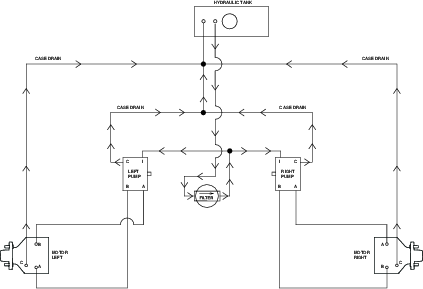
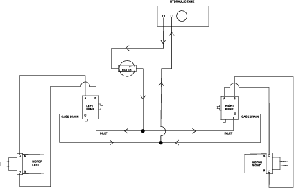
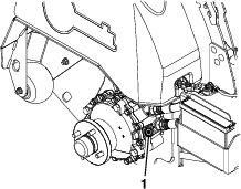
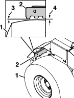
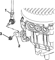
Hydraulic System Air Purge
Air must be purged from the hydraulic system when any hydraulic components, including oil filter, are removed or any of the hydraulic lines are disconnected.
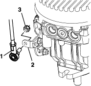
The critical area for purging air from the hydraulic system is between the oil reservoir and each charge pump located on the top of each variable displacement pump (Figure 27). Air in other parts of the hydraulic system will be purged through normal operation once the charge pump is “primed”.
-
Stop engine and wait for all moving parts to stop. Raise the rear of the machine up onto jack stands high enough to raise the drive wheels off the ground.
-
Check oil level as stated in Check Hydraulic Oil Level section.
-
Start engine and move throttle control ahead to full throttle position. Disengage parking brake and move motion control levers forward with equal pressure.
If either drive wheel does not rotate, it is possible to assist the purging of the charge pump by carefully rotating the tire in the forward position.
Note: It is necessary to lightly touch the pump to check the pump temperature. If the pump is too hot to touch, turn off engine. The pumps may be damaged if the pump becomes too hot.
If either drive wheel still does not rotate continue with step 4.
-
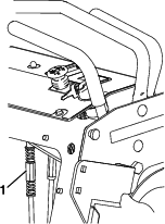
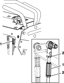
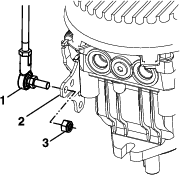
Open the bypass valve (shown in Figure 27).
-
With the bypass valve open and the engine running, slowly move the motion control levers in both forward and reverse directions five to six times. As air is purged from the unit, the oil level in the reservoir will drop.
-
Close the bypass valve. With the bypass valve closed and the engine running, slowly move the motion control levers in both forward and reverse directions five to six times.
-
Allow unit to run several minutes after the charge pumps are “primed” with drive system in the full speed position. Check oil level as stated in Check the Hydraulic Oil Level section.
-
Check hydro drive linkage adjustment as stated in Hydro Drive Linkage Adjustment section in Adjustments.
Wheel Hub Nut Specification–S-Series Only
| Maintenance Service Interval | Maintenance Procedure |
|---|---|
| After the first 100 hours |
|
| Every 500 hours |
|
Torque the nut on the wheel motor tapered shaft to 211-260 ft-lb (286-352 N-m).
Note: Do Not use anti-seize compound on the wheel hub.
Check Spark Arrester
| Maintenance Service Interval | Maintenance Procedure |
|---|---|
| Every 50 hours |
|
Warning
Hot exhaust system components may ignite gasoline vapors even after the engine is stopped. Hot particles exhausted during engine operation may ignite flammable materials. Fire may result in personal injury or property damage.
Do Not refuel or run engine unless spark arrester is installed.
-
Stop engine, wait for all moving parts to stop, and remove key. Engage parking brake.
-
Wait for muffler to cool.
-
If any breaks in the screen or welds are observed, replace arrester.
-
If plugging of the screen is observed, remove arrester and shake loose particles out of the arrester and clean screen with a wire brush (soak in solvent if necessary). Reinstall arrester on exhaust outlet.
Thread Locking Adhesives
Thread locking adhesives such as “Loctite 242” or “Fel-Pro, Pro-Lock Nut Type” are used on the following fasteners:
-
Pump sheave screws.
-
Sheave retaining bolt in end of engine crankshaft.
General Purpose Grease (Or Food-Grade Anti-seize)
General purpose grease (or food-grade anti-seize) is used in the following locations:
—Between splines of the cutter housing spindle and sheave.
Copper-Based Anti-seize
Copper-based anti-seize is used in the following locations:
-
On threads of Blade Bolts. See Check Mower Blades section.
-
Between engine crankshaft, PTO shaft, and PTO pulley.
-
Between pump shafts and sheaves.
Dielectric Grease
Dielectric grease is used on all blade type electrical connections to prevent corrosion and loss of contact. Dielectric grease should not be applied to sealed connectors.
Adjustments
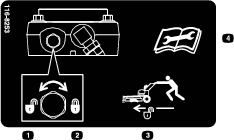
Note: Disengage PTO, shut off engine, wait for all moving parts to stop, engage parking brake, and remove key before servicing, cleaning, or making any adjustments to the machine.
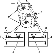
Deck Leveling
Note: Small adjustments can be accomplished by increasing the tire pressure in the tire on the low side.
-
Adjust the height — to increase, turn the adjuster screw clockwise; to decrease, turn counterclockwise.
-
Loosen the jam nuts on the top of each deck adjuster. Fine tune the adjuster on the front deck lift assembly by turning it to get the correct height for the center deck left and right front blade tips
-
Measure the back tip height. Fine tune rear adjusters as required
-
Re-measure until all four sides are the correct height. Tighten all the jam nuts on the deck lift arm assemblies
-
Position the mower on a flat surface.
-
Stop engine, wait for all moving parts to stop, and remove key. Engage parking brake.
-
Check the tire pressure in drive tires and pneumatic front caster tires (if equipped). Proper inflation pressure for tires is 13 psi (90 kPa). Adjust if necessary
-
Push the button down on top of the lever to disengage the deck lift latch. Pull the handle all the way rearward and release the button to latch the cutting deck into the raised transport position.
-
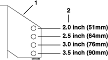
Insert the height adjustment pin into the 3 inch (7.6 cm) cutting height location.
-
Slightly pull the handle rearward and push the button down on top of the lever to disengage the transport lock. Allow the handle to move forward to lower the cutting deck to the cutting height.
-
Raise the discharge deflector.
-
Carefully rotate the blades front to rear. Measure from the level surface to the front tip of the center blade. The measurement should read 3 inches (7.6 cm).
Note: In most conditions, the back tips on the side blades should be adjusted 1/8-1/4 inch (3.2-6.4 mm) higher than the front.
-
Raise the deck to transport position.
Pump Drive Belt Tension
Self-tensioning - No adjustment necessary.
Mower Deck Drive Belt Tension
Self-tensioning - No adjustment necessary.
Park Brake Adjustment–S-Series Only
If the parking brake does not hold securely, an adjustment is required.
-
Park the machine on a level surface.
-
Shut off engine and wait for all moving parts to stop.
-
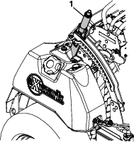
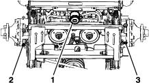
When the park brake is released, the brake bars should lift off the tires and the hand lever should travel forward. When the brake is disengaged, the gap between the brake snubber teeth and drive tire on the right side of the machine should measure 1/4–3/8 inch (6–10 mm) (see Figure 30).
-
48 and 52 Inch Models: Measure from center teeth
-
60 Inch Model: Measure from outer tooth
-
-
If the parking brake still does not hold securely, an adjustment is required. To adjust the brake, loosen whizlock nuts and slide the lower link up or down until the measurement is achieved.
-
Tighten the whizlock nuts to 27-33 ft lb (37-45 N-m).
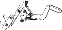
Motion Control Tracking Adjustment
If the machine travels or pulls to one side when the motion control levers are in the full forward position, adjust the rear control links.
-
Remove the thigh pad.
-
Adjust the rear control link (see Figure 32).
-
Shorten link to increase speed.
-
Lengthen link to decrease speed.
-
-
Replace thigh pad.
-
Drive the machine and check the full forward tracking.
-
Repeat steps 1 through 4 until desired tracking is obtained.
Note: The motion control lever needs to be in neutral while making any necessary adjustments.
Motion Control Neutral Lock Adjustment
There is a plate under the control panel that engages notches in the motion controls when the brake is applied in neutral. If the parking brake plate tabs do not engage these notches, adjust the front control links.
-
Slowly apply the brake while observing the tabs of the brake plate engaging the notches in the motion controls. The lock plate should drop easily and freely into the notches on each side.
-
Check that controls are in neutral. Adjust each side via the front control link (see Figure 33).
-
Remove the thigh pad.
-
Loosen upper and lower jam nuts at the top of the front control link.
-
Lengthen link to move control rearward.
-
Shorten link to move control forward.
-
-
Partially cycle brake on and off to observe plate movement in and out of notch.
-
Tighten jam nuts.
-
Replace thigh pad.
-
Check full forward tracking.
Motion Control Lever–Drive Comfort Adjustment
-
Remove the thigh pad.
-
The motion control link can be adjusted into the following positions to decrease the amount of force on the motion control levers.
-
Maximum force (factory setting) / Maximum speed forward and reverse:
-
Medium force / Reduced speed forward and reverse:
Remove the pump control bracket and position the link directly to the inside of the pump control arm.
-
Minimum force / Slowest speed forward and reverse:
Place the linkage on the outside of the pump control bracket.
-
Cleaning
Cleaning and Storing Safety
-
Park machine on level ground, disengage drives, set parking brake, stop engine, remove key, and disconnect spark plug wire. Wait for all moving parts to stop before leaving the operator’s position. Allow the machine to cool before servicing, adjusting, fueling, cleaning, or storing.
-
Clean grass and debris from the cutting unit, muffler, drives, grass catcher, and engine compartment to prevent fires.
-
Allow the machine to cool before storing the machine in any enclosure. Do not store the machine or fuel container, or refuel, where there is an open flame, spark, or pilot light such as on a water heater or other appliance.
Clean Debris From Machine
| Maintenance Service Interval | Maintenance Procedure |
|---|---|
| Before each use or daily |
|
-
Stop engine, wait for all moving parts to stop, and remove key. Engage parking brake.
-
Clean off any oil, debris, or grass build-up on the machine and cutting deck, especially under deck belt shields, around the fuel tank, around engine and exhaust area.
Important: You can wash the machine with mild detergent and water. Do not pressure wash the machine. Avoid excessive use of water, especially near the control panel, around the engine, hydraulic pumps, and motors.
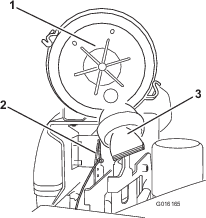
Clean Engine and Exhaust System Area
| Maintenance Service Interval | Maintenance Procedure |
|---|---|
| Before each use or daily |
|
Caution
Excessive debris around engine cooling air intake and exhaust system area can cause engine, exhaust area, and hydraulic system to overheat which can create a fire hazard.
Clean all debris from engine and exhaust system area.
-
Stop engine, wait for all moving parts to stop, and remove key. Engage parking brake.
-
Clean all debris from rotating engine air intake screen, around engine shrouding, and exhaust system area.
-
Wipe up any excessive grease or oil around the engine and exhaust system area.
-
Clean oil coolers (if equipped) of all debris, dirt, and oil.
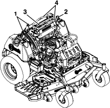
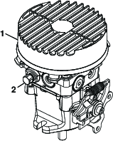
Remove Engine Shroud Access Panels and Clean Cooling Fins
| Maintenance Service Interval | Maintenance Procedure |
|---|---|
| Every 80 hours |
|
-
Stop engine, wait for all moving parts to stop, and remove key. Engage parking brake.
-
Remove cooling shroud access panels from engine and clean cooling fins. Also clean dust, dirt, and oil from external surfaces of engine which can cause improper cooling.
-
Make sure cooling shroud access panels are properly reinstalled. Operating the engine without cooling shroud access panels will cause engine damage due to overheating.
Clean Grass Build-Up Under Deck
| Maintenance Service Interval | Maintenance Procedure |
|---|---|
| Before each use or daily |
|
-
Stop engine, wait for all moving parts to stop, and remove key. Engage parking brake.
-
Raise deck to the transport (maximum cutting height) position. Lift the front of unit and support machine using jack stands or equivalent support.
-
Clean out any grass build-up from underside of deck and in discharge deflector.
Waste Disposal
Motor Oil Disposal
Engine oil and hydraulic oil are both pollutants to the environment. Dispose of used oil at a certified recycling center or according to your state and local regulations.
Battery Disposal
Danger
Battery electrolyte contains sulfuric acid, which is poisonous and can cause severe burns. Swallowing electrolyte can be fatal or if it touches skin can cause severe burns.
-
Wear safety glasses to shield eyes, and rubber gloves to protect skin and clothing when handling electrolyte.
-
Do Not swallow electrolyte.
-
In the event of an accident, flush with water and call a doctor immediately.
Federal law states that batteries should not be placed in the garbage. Management and disposal practices must be within relevant federal, state, or local laws.
If a battery is being replaced or if the unit containing the battery is no longer operating and is being scrapped, take the battery to a local certified recycling center. If no local recycling is available return the battery to any certified battery reseller.