For machines with serial numbers 239999999 and before, decal 93-9861 is not included in the kit. You must purchase decal 93-9861 separately and apply it.
Safety
Safety and Instructional Decals
 |
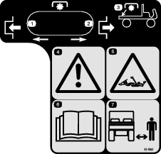
Safety decals and instructions are easily visible to the operator and are located near any area of potential danger. Replace any decal that is damaged or missing. |
Installation
Preparing the Machine
-
Park the machine on a level surface.
-
For machine models with a utility bed, perform the following:
-
Raise the bed until the lift cylinders are fully extended; refer to the Operator’s Manual for the machine.
-
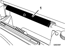
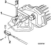
Remove the bed support from the storage brackets on back of the ROPS panel (Figure 1).
-
Push the bed support onto the cylinder rod, making sure the support end tabs rest on the end of cylinder barrel and on the cylinder rod end (Figure 2).
-
-
Engage the parking brake.
-
Shut off the engine and remove the key.
-
Allow machine to cool.
-
Disconnect the battery as follows:
-
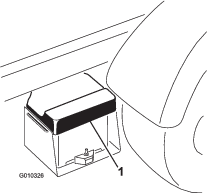
Squeeze the battery cover to release the tabs from battery base (Figure 3).
-
Remove the battery cover from the battery base (Figure 3).
-
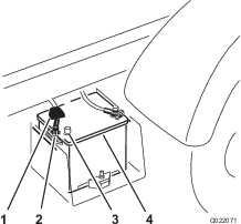
Remove the terminal of the positive battery cable from the battery post (Figure 4).
Note: Ensure that the terminal positive battery cable does not touch the battery post.
-
Installing the PTO Controls
Installing the Levers
Important: Use the instructions in steps 1 through 15 when installing the kit on a vehicle with a serial number greater than 240000001; otherwise skip to Connecting the PTO Cable.
-
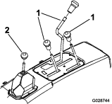
Unscrew and remove all of the knobs from the console levers and from the gear shift lever (Figure 5).
-
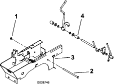
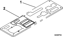
Remove the 6 screws that secure outside edge of the center console cover plate to the frame and remove the cover plate (Figure 6).
-
Disconnect the reservoir hose from the radiator and plug or clamp the hose to retain the coolant (Figure 6).
-
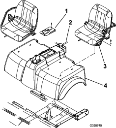
Remove the 8 capscrews securing the seats and shroud to the mounting brackets (Figure 6). Remove seats and shroud.
-
Remove the cotter pins and clevis pins that secure the cables to the console levers (Differential Lock, Hi–Low and Hydraulic Lift). Retain cotter pins and clevis pins.
Note: Retain the cotter pins and clevis pins.
-
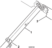
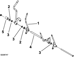
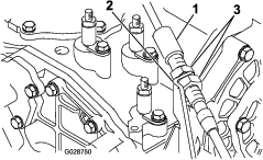
Remove the nut and bolt securing the console levers to lever the support bracket (Figure 7) and the remove console lever assembly from the lever-support bracket.
-
Remove the spacer (Figure 7) from the assembly and install the new PTO lever in its place on the pivot tube.
Note: Position the lever as shown in Figure 8.
-
Install the previously removed components onto bolt, positioning each as shown in Figure 8.
-
Secure the bolt to the lever support bracket with the nut that you removed previously (Figure 8).
Installing the PTO Cable
Routing the PTO Cable
-
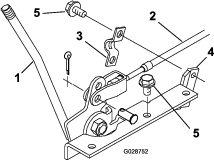
Route the PTO cable under the rear of the lever support bracket.
-
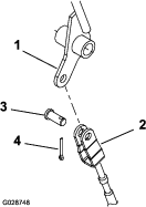
Connect the PTO cable clevis to the hole in PTO lever with a clevis pin and a cotter pin (Figure 9).
-
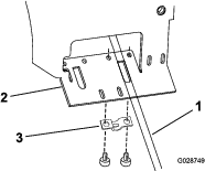
Secure the PTO cable to underside of the lever support bracket with a clamp and 2 hex-socket head self-tapping screws (Figure 10).
Note: The PTO lever should be positioned so it is in line with the Hi–Low lever (Engaged position) when the transaxle is shifted into the Low position.
-
Route the cable, along the existing cables, and to the cable bracket mounted at front left corner of the transaxle (Figure 11).
-
Loosen the rear jam nuts on the PTO cable and insert the end of cable into the opening in the bracket. Loosely secure the PTO cable to the bracket with the jam nuts.
-
Install the shroud, seats, console cover plate, and lever knobs onto the machine; refer to step 2 in Installing the PTO Controls.
Note: When the PTO is engaged, the lever must not contact the center console plate.
Connecting the PTO Cable
Important: Accomplish the installation steps in Connecting the PTO Cable only when installing the kit on a machine with a serial number prior to 239999999; otherwise skip to Installing the PTO to the Transaxle.
Note: Some of the parts required to install this kit on machines with serial numbers prior to 239999999 are not included in the kit, but are listed in the parts catalog.
-
Remove all of the knobs from the center console levers (Figure 12).
-
Remove the 6 screws that secure the outside edge of center console cover plate to the frame and remove cover plate (Figure 12).
-
Connect the PTO cable clevis to the bottom hole in PTO lever with a clevis pin and cotter pin (Figure 13)
-
Secure the PTO cable to the PTO lever support with a clamp and 2 self tapping screws (Figure 13).
-
Insert the other end of the PTO lever cable through the opening in right side of the console and through the cable holder in the rear of the console (Figure 14).
Note: Route the cable, along the existing cables to the cable bracket mounted at the front left corner of the transaxle.
-
Loosen the rear jam nuts on cable and insert the end of cable into the opening in the bracket. Loosely secure the PTO cable to the bracket with the jam nuts.
-
Using the 3 self tapping screws supplied in the kit, mount the PTO lever support to the right side of console.
Note: The lever location is shown in Figure 8.
-
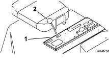
Clean console plate and install the operation decal to the console next to PTO lever, locating the decal as shown in Figure 15.
-
Install the console cover plate and the lever knobs to machine.
Note: When the PTO is engaged, the lever must not contact the center console plate.
Installing the PTO to the Transaxle
Removing the Transaxle Cover Plate
Note: The remaining steps pertain to installing the kit on all vehicles unless otherwise specified.
-
Disconnect the hydraulic hose from the fitting on transaxle cover plate (Figure 16).
Note: Cap the hose end to prevent contaminants from entering the hose.
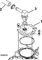
-
Remove the fitting from cover plate.
-
Install the small O-ring onto the fitting as shown in Figure 17.
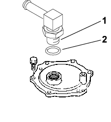
-
Install the fitting into the front of the new PTO and position the fitting as shown in Figure 18.
-
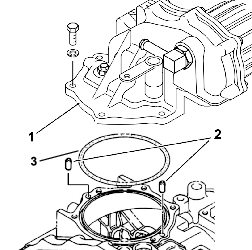
Remove the 5 bolts, lock washers, and nut that secure the cover plate to the transaxle and carefully remove the cover plate to prevent damage to the O-ring seal (Figure 18).
Note: Retain the fasteners for installation later.
Installing the PTO
-
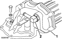
Install the 2 alignment pins into the holes in the transaxle, at locations shown in Figure 19.
-
Use the large O-ring, mounting bolts, lock washers, and nut that you removed from the transaxle cover plate mount the PTO assembly onto the transaxle (Figure 19).
Note: When mounting the PTO assembly, make sure that the large O-ring is positioned properly in the transaxle groove to prevent damage. Do not reuse an old O-ring.
-
Remove the cap from the disconnected hydraulic hose and install the hose to the PTO fitting with the previously removed clamp.
Note: Make sure the hose and fitting are clean before you connect them.
-
Move the PTO lever at the center console all the way back (towards the rear of the console) and move the PTO lever arm (Figure 20) on the transaxle to the right side (passenger side).
-
Adjust the cable clevis, jam nuts, or both clevis and nuts (which secure the cable to the bracket) until the clevis pin drops freely through the aligned mounting holes in the clevis and lever arm (Figure 20).
-
Secure the clevis pin with the cotter pin and tighten jam nut that secures the cable to the cable clevis, then tighten the jam nuts that secure the cable to the bracket.
-
Remove the jumper cable from the wire harness located in front of the PTO.
-
Route the wire harness under the positive battery cable and connect the wire—harness connector into the PTO switch connector.
-
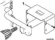
Mount the PTO shield to the rear frame tube with 4 capscrews, 2 spacers, and 4 locknuts (Figure 21).
-
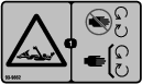
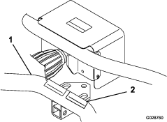
Apply the warning decal to the lower-rear cross tube next to the existing decal, just above hitch point (Figure 22).
-
Use the 5 cable ties supplied in the kit to secure the PTO cable to the existing wiring harness.
Completing the PTO Installation
-
Connect the battery cables to the battery and install the battery cover; refer to Preparing the Machine.
-
Test the interlock system; refer to Checking the Interlock System in the Operator’s Manual.
-
Shut off the engine and inspect the machine for hydraulic fluid leaks where the PTO housing mounts onto the transaxle.
Note: Repair all fluid leaks.
-
Start the engine and operate the PTO.
-
Remove the cylinder lock from the bed-lift cylinder and stow it in the brackets at the back of the ROPS panel; refer to Preparing the Machine.
-
Lower the bed and shut off the engine.
Operation
Warning
The vehicle may move unexpectedly if the PTO is engaged and the vehicle is shifted into gear, which could result in serious injury to a bystander.
-
Do not shift the transmission into gear until the PTO attachment has stopped rotating, even if the clutch is depressed.
-
Ensure that no bystanders are near the PTO output shaft or the front or rear of vehicle.
Danger
An uncovered rotating spline can catch clothing and result in serious injury or death.
-
When an attachment is not connected to the PTO shaft, disengage the drive to the PTO by pulling back on PTO lever.
-
The PTO includes a shield. This shield must remain installed on the vehicle and in good condition.
-
Always disengage the PTO and shut off the engine before coupling any attachment to the PTO shaft.
Caution
Using attachments with high inertia (i.e. mowers or blowers) will increase the amount of force required to shift the vehicle and will damage the transaxle if frequently shifted.
-
Do not shift the vehicle while the vehicle is moving if the PTO is engaged.
-
Always use the optional overrunning clutch when powering a high-inertia attachment with the PTO.
Description of Operation
The PTO takes power from the engine, through the transaxle, and supplies power through a standard 540 rpm-splined shaft at the rear of the vehicle. PTO power can be used for both mobile and stationary attachments.
Note: Refer to attachment Operator’s Manual for rpm recommendations.
Mobile PTO Operation
Important: When operating the PTO, the machine must not be moving when PTO is started.
-
Engage the parking brake.
-
Shift the transmission into the NEUTRAL position.
-
Fully depress the clutch pedal and start the engine.
Note: The engine will not crank unless the PTO lever is in the OFF position.
-
Shift the PTO lever as follows:
Important: Do not engage or disengage PTO while moving otherwise damage to the PTO will occur. Always stop vehicle before shifting PTO.
-
For machines with serial numbers 239999999 and before, move PTO lever fully forward to the ENGAGE position.
-
For machines with serial numbers 240000000 and after, move PTO lever fully rearward to the ENGAGE position.
-
-
Shift the transmission into the desired gear.
-
Disengage the parking brake.
-
Slowly release the clutch pedal.
To stop the PTO operation, fully depress the clutch pedal and move PTO lever to the DISENGAGE position.
Note: You may stop the PTO momentarily by fully depressing the clutch pedal and allowing machine to come to a complete stop.
Stationary PTO Operation
Important: When operating the PTO, the machine must not be moving when PTO is started.
-
Engage the parking brake.
-
Shift the transmission into the NEUTRAL position.
-
Fully depress the clutch pedal and start the engine.
Note: The engine will not crank unless the PTO lever is in the Disengage position.
-
Shift the PTO lever as follows:
Important: Do not engage or disengage PTO while moving otherwise damage to the PTO will occur. Always stop vehicle before shifting PTO.
-
For machines with serial numbers 239999999 and before, move PTO lever fully forward to the ENGAGE position.
-
For machines with serial numbers 240000000 and after, move PTO lever fully rearward to the ENGAGE position.
-
-
Slowly release the clutch pedal.
To stop the PTO operation, fully depress clutch pedal and shift PTO lever to the DISENGAGE position.
Note: You may stop the PTO momentarily by fully depressing the clutch pedal and allowing transaxle and PTO to come to a complete stop.