Installation
Preparing the Machine
-
Position the machine on a level surface, lower the cutting units, shut off the engine, engage the parking brake, and remove the key from the ignition.
-
Disconnect the negative battery cable from the battery.
-
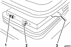
Disconnect the seat switch wire from the harness at the rear of the control arm.
-
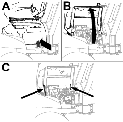
Remove the 2 adjusting bolts securing the control arm to the seat mount (Figure 1). Carefully set the control arm aside.
Important: Ensure that you do not damage the wire harness or the throttle cable.
-
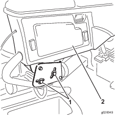
Remove the 4 nuts securing the seat adjusters and the manual tube clamps to the seat suspension (Figure 2).
-
Remove the 4 washers between the seat adjusters and seat suspension and remove the seat assembly; carefully set the seat assembly aside.
-
Remove the 4 bolts, spacers, and nuts securing the lower seat brackets to the seat base (Figure 2).
-
Remove the seat suspension and the seat brackets from the seat base.
Important: Ensure that you do not misplace the spacers during removal.
-
Remove the 4 bolts securing the seat suspension to the lower seat brackets (Figure 2).
Important: Retain the removed bolts and brackets for later installation.
Installing the Seat
Parts needed for this procedure:
| Air ride seat suspension assembly | 1 |
-
Secure the air ride seat suspension to the lower seat brackets with the 4 bolts previously removed (Figure 2).
Note: When assembling the seat components, use the front mounting holes in the seat and the rear mounting holes in the suspension.
-
Mount the lower seat brackets to the seat base with the 4 bolts, spacers, and nuts previously removed (Figure 2).
-
Position the seat assembly onto the seat suspension. Ensure that a washer is on each adjuster stud before placing it on the suspension (Figure 2).
-
Secure the seat adjusters and the manual tube clamps to the seat suspension with the 4 nuts previously removed (Figure 2).
-
Install the control arm with the 2 control arm adjusting bolts previously removed (Figure 1). Adjust as desired.
Connecting the Seat
Parts needed for this procedure:
| Fuse – 20 A (for use on machines without an air ride suspension fuse slot only) | 1 |
| Fuse block (for use on machines without an air ride suspension fuse slot only) | 1 |
| Screw (for use on machines without an air ride suspension fuse slot only) | 2 |
Determining the Appropriate Seat Connection
There are 3 configurations for connecting the seat. Determine the appropriate configuration for your machine:
If your machine has a fuse block in the control arm without an air ride suspension fuse slot, refer to Installing the Fuse Block and Connecting the Seat.
If your machine has a fuse block in the control arm with an air ride suspension fuse slot, refer to Checking the Fuse in the Arm Console.
If your machine does not have a fuse block in the control arm, refer to Checking the Fuse Under the Seat.
Installing the Fuse Block and Connecting the Seat
-
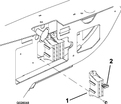
Remove the access panel from the side of the control arm.
-
Mount the fuse block next to the existing fuse block with 2 screws (#8 x 1/2 inch) as shown in Figure 3.
-
Connect the large red wire from the traction unit wire harness to the wire on the fuse block.
-
Connect the red wire with the white stripe labeled “Air Ride Seat” to one of the red wires from the fuse block.
-
Insert the 20 A fuse into the fuse slot where the wire is connected.
-
Install the access panel to the control arm (Figure 1).
-
Plug the traction unit power harness from the back of the control arm into the seat harness connector.
Checking the Fuse in the Arm Console
-
Remove the access panel from the side of the control arm.
-
Ensure that there is a 20 A fuse in the air ride suspension fuse slot.
-
Plug the traction unit power harness from the back of the control arm into the seat harness connector.
Checking the Fuse Under the Seat
-
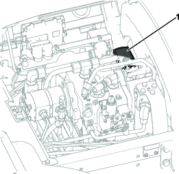
Unlatch, tilt open, and support the seat base with the prop rods.
-
Refer to the decal on the fuse block cover to locate the air ride suspension fuse slot.
-
Remove the cover from the fuse block.
-
Ensure that there is a 20 A fuse in the air ride suspension fuse slot.
-
Plug the traction unit power harness from the back of the control arm into the seat harness connector.
Completing the Installation
-
Slide the seat completely forward and backward to ensure proper operation and that the seat wires and connectors are not pinched or do not contact any moving parts.
-
Connect the negative battery cable to the battery.