Warning
Hydraulic fluid escaping under pressure can penetrate skin and
cause injury. Seek immediate medical attention if hydraulic fluid
is injected into your skin.
-
Ensure that all hydraulic-fluid hoses and lines are
in good condition and all hydraulic connections and fittings are tight
before applying pressure to the hydraulic system.
-
Keep your body and hands away from pinhole leaks or
nozzles that eject high-pressure hydraulic fluid.
-
Use a piece of cardboard or paper to find hydraulic
leaks.
-
Release all pressure in the hydraulic system before
performing any work on the system.
Preparing the Machine
-
Park the machine on a level surface.
-
Ensure that the transmission is in neutral.
-
Lower all attachments (if equipped).
-
Engage the parking brake.
-
Shut off the engine and remove the key.
-
Remove all attachments (if equipped).
-
Raise the front and rear of the machine; refer to
the Pre-Maintenance Procedures section in your traction unit Operator’s Manual.
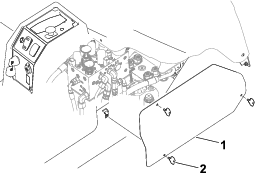
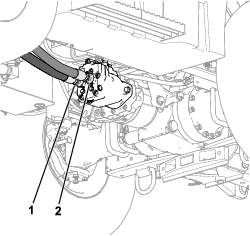
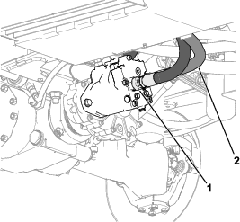
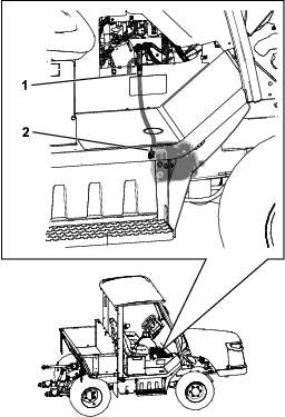
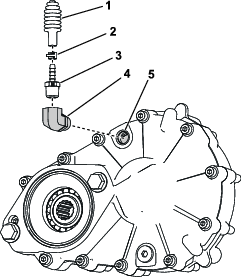
Removing the Front 2-Speed Hydraulic Hose
-
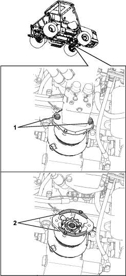
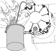
Remove the access panel from the right side of the
control console (Figure 1).
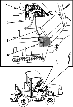
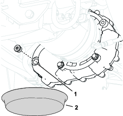
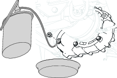
-
Remove and discard the front 2-speed
hydraulic hose (Figure 2) from the front hydraulic motor and the tee fitting
on the hydraulic manifold.
Note: The rear 2-speed hydraulic hose should
remain installed on the tee fitting.
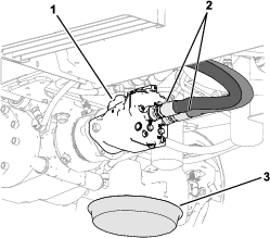
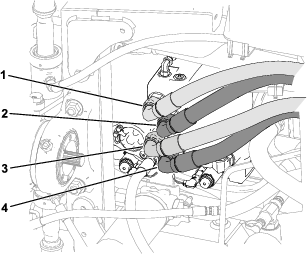
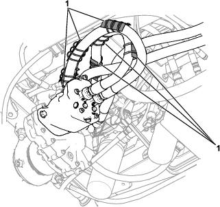
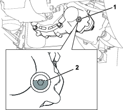
Removing the Hydraulic Hoses from the Hydraulic Pump and Motors
Note: You can use a drain pan to collect any hydraulic fluid that
drains from the machine.
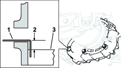
-
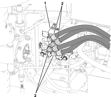
Remove the hydraulic hoses (shown in Figure 3) from the
front hydraulic motor.
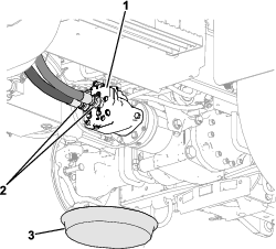
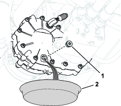
-
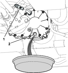
Remove the hydraulic hoses (shown in Figure 4) from the
rear hydraulic motor.
-
Remove the hydraulic hoses (shown in Figure 5) from the
hydraulic pump.
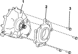
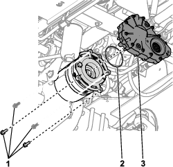
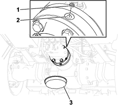
Removing the Hydraulic Motors from the Axles
-
Remove the bolts that secure the hydraulic motor to
the front axle (Figure 6). Retain the bolts.
-
Remove the bolts and the thin sheet metal covers (Figure 6). Discard
the bolts and metal covers.
-
Drain the parking-brake fluid at the rear axle (Figure 7).
Note: This reduces the mess when the hydraulic motor and parking brake
are separated from the axle.
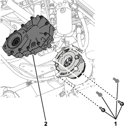
-
Remove the 2 bolts that secure the hydraulic motor
to the parking brake and the rear axle (Figure 8).
-
Retain the bolts (1/2 x 5 inches) for installing the
gearbox adapter to the parking brake.
-
There is a gasket that seals the surface between the
parking brake and the hydraulic motor (shown in Figure 11). Install a new gasket when
you install the gearbox adapter. The gasket is not needed on the front
axle.
Note: The parking brake should remain mounted to the axle.
Installing the Hoses to the Hydraulic Pump
Parts needed for this procedure:
| Hydraulic hose (109 cm or 43 inches) | 2 |
| Hydraulic hose (122 cm or 48 inches) | 2 |
Connect the appropriate hydraulic hoses to the hydraulic-pump
ports as shown in Figure 9.
Note: The curved end of each hose must be installed to the pump. The
straight end of each hose will be installed to the motors later.
Installing the Gearboxes
Parts needed for this procedure:
| Gearbox | 2 |
| Gearbox adapter | 2 |
| Gasket | 1 |
| O-ring (3 inches) | 1 |
| Bolt (3/8 x 1-1/4 inches) | 8 |
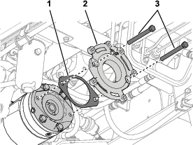
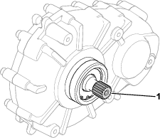
-
Remove the gearbox adapters from the gearboxes (Figure 10).
-
Install a gearbox adapter and a gasket on the rear
axle using the existing bolts (1/2 x 5 inches). Position the adapter
with “” towards the top of the machine (Figure 11).
Torque the bolts
to 98 to 106 N∙m (72 to 78 ft-lb).
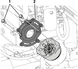
-
Install a gearbox adapter on the front axle using
the existing bolts. Position the adapter with “” towards the
top of the machine (Figure 12).
Torque the bolts to 98 to 106 N∙m (72
to 78 ft-lb).
-
Apply anti-seize compound to all surfaces of the gearbox
output-shaft splines prior to installation (Figure 13).
-
Lightly oil the O-ring (3 inches) and install the
O-ring and a gearbox on the rear axle (Figure 14).
Note: The gearbox will pilot onto the adapter; there are 4 mounting
holes that will line up with the adapter.The gearbox should be positioned horizontally to the ground.
-
Use 4 hex-head bolts (3/8 x 1-1/4 inches) to secure
the gearbox to the adapter (Figure 15); torque the bolts to 39 to
45 N∙m (29 to 33 ft-lb).
-
Apply anti-seize compound to all surfaces of the output-shaft
splines for the second gearbox (Figure 13).
-
Install the second gearbox on the front axle (Figure 15).
Note: The hydraulic motor mount will be angled with respect to the
ground.
-
Use 4 hex-head bolts (3/8 x 1-1/4 inches) to secure
the gearbox to the adapter (Figure 15); torque the bolts to 39 to
45 N∙m (29 to 33 ft-lb).
Installing the Hydraulic Motors
Parts needed for this procedure:
| O-ring (3-3/4 inches) | 2 |
| Hex-head bolt (1/2 x 1-1/4 inches) | 4 |
-
Prior to installing the hydraulic motors, lightly
oil an O-ring and install onto the hydraulic-motor pilot. Ensure that
the O-ring is not twisted.
-
Apply anti-seize compound to all surfaces of the motor
output-shaft splines.
-
For each hydraulic motor, use 2 hex-head bolts (1/2
x 1-1/4 inches) to secure the motor to the gearbox (Figure 16).
Torque the bolts to 98 to 106 N∙m (72 to 78 ft-lb).
Installing the Hydraulic Hoses to the Motors
Parts needed for this procedure:
| Hydraulic hose (73-2/3 cm or 29 inches) | 1 |
| Hose protector | 6 |
| Cable tie | 18 |
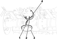
Installing the Hydraulic-Pump Hoses to the Motors
The following table shows the appropriate hose connections. Figure 17 identifies
the hose connections at the hydraulic pump.
Motor Port and Pump Port Connections
| Pump Port | Motor | Motor Port | Figure 9 Callout |
| A | Front | M2 | 1 |
| B | Front | M1 | 2 |
| D | Rear | M1 | 3 |
| C | Rear | M2 | 4 |
-
Connect the previously installed hydraulic-pump hoses
to the hydraulic motors as follows:
-
Connect the hydraulic hoses (109 cm or 43 inches)
to the rear hydraulic motors (Figure 18).
-
Connect the hydraulic hoses (122 cm or 48 inches)
to the front hydraulic motors (Figure 19).
-
Use the cable ties to secure the hose protectors to
the hydraulic hoses (109 cm or 43 inches) as shown in Figure 20.
-
Torque the hose fittings to 149 to 164 N∙m (110 to
121 ft-lb).
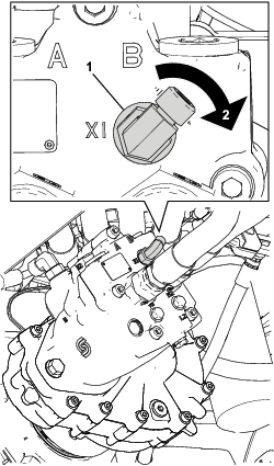
Installing the 2-Speed Hose
-
Adjust the 2-speed 90° hydraulic
fitting on the front hydraulic motor by 25° clockwise (Figure 21).
Torque the elbow to 81 to 89 N∙m (60 to 66 ft-lb).
-
Install the new hydraulic hose (73-2/3 cm or 29 inches)
as follows (Figure 22):
-
Install the hose to the motor fitting that you adjusted
in Step 1; torque the hose fitting to 24 to 27 N∙m (18 to 20 ft-lb).
-
Install the hose to the tee fitting at the hydraulic
manifold; torque the hose fitting to 41 to 45 N∙m (30 to 33 ft-lb).
Installing the Hydraulic Fitting and Bellows to the Gearboxes
Parts needed for this procedure:
| 90° hydraulic fitting | 2 |
| Hose barb | 2 |
| Spring clamp | 2 |
| Bellows | 2 |
| Sight plug | 1 |
| Pipe sealant compound (not included) | – |
| Thread-sealing tape (not included) | – |
-
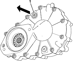
Remove the plug on the upper area of both gearboxes
(Figure 23)
and discard it.
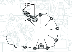
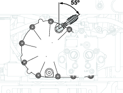
-
Install a 90° hydraulic fitting oriented 55°
from vertical on the gearbox (as shown in Figure 24 and Figure 25); torque the fitting to 49
to 54 N∙m (36 to 40 ft-lb).
Note: The fitting must be tilted so the bellows do not contact other
parts.
-
Apply pipe sealant compound or thread-sealing tape
to the threads on the hose barb.
-
Install the hose barb into the hydraulic fitting (Figure 26).
-
Install the spring clamp to the bellows and secure
the bellows to the hose barb with the spring clamp (Figure 26).
-
Remove the plug from the front of the front gearbox
and replace it with the included sight plug.
Adding Fluid to the Gearboxes
Fluid specification: Toro Premium Tractor
Fluid
Add fluid to the front and rear gearboxes; refer to Changing the Front Traction-Gearbox Oil and Changing the Rear Traction-Gearbox Oil.
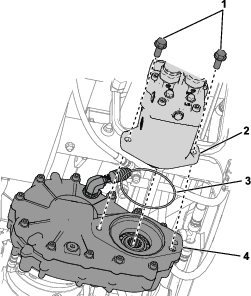
Adding Fluid to the Parking Brake
Fluid specification: Toro Premium Tractor
Fluid
-
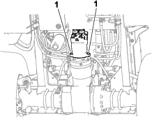
Remove the fill plug at the top of the brake housing
(Figure 27).
-
Fill the brake housing with 160 ml (5.4 fl oz) of
the specified oil through the fill port.
-
Apply PTFE thread sealant to the fill plug (Figure 27) and tighten
it 3 turns past finger-tight.
Updating the Traction-Unit Software
Use Toro DIAG to update the traction-unit software to Rev H; refer to the Toro DIAG Software User’s Guide for instructions to update the software.
Completing the Installation
Perform the following steps to complete the installation:
-
Check the hydraulic-fluid level and add more fluid
as needed; refer to the hydraulic system maintenance section in the
traction unit Operator’s Manual.
-
Ensure that the machine moves forward when the shift
lever is in the FORWARD position; ensure
that it moves backward when the lever is in the REVERSE position.
-
Ensure that the machine does not move faster than
23 km/h (14 mph) during operation. The InfoCenter displays the current
machine speed.
-
Ensure that there are no unusual noises or leaks.
-
Ensure that the machine operates smoothly when changing
speed or direction.