Introduction
The AutoSteer kit is an accessory for the GeoLink spray system, used for a turf spray application vehicle, and is intended to be used by professional, hired operators in commercial applications. It is designed primarily for spraying on well-maintained lawns in parks, golf courses, sports fields, and on commercial grounds. Using this product for purposes other than its intended use could prove dangerous to you and bystanders.
Read this information carefully to learn how to operate and maintain your product properly and to avoid injury and product damage. You are responsible for operating the product properly and safely.
Visit www.Toro.com for product safety and operation training materials, accessory information, help finding a dealer, or to register your product.
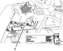
Whenever you need service, genuine Toro parts, or additional information, contact an Authorized Service Dealer or Toro Customer Service and have the model and serial numbers of your product ready. Figure 1 identifies the location of the model and serial numbers on the product. Write the numbers in the space provided.
Important: With your mobile device, you can scan the QR code (if equipped) on the serial number plate to access warranty, parts, and other product information.
This manual identifies potential hazards and has safety messages identified by the safety-alert symbol (Figure 2), which signals a hazard that may cause serious injury or death if you do not follow the recommended precautions.

This manual uses 2 words to highlight information. Important calls attention to special mechanical information and Note emphasizes general information worthy of special attention.
Safety
Warning
Chemical substances used in the spray system may be hazardous and toxic to you, bystanders, animals, plants, soil, or other property.
-
Carefully read and follow the chemical warning labels and safety data sheet (SDS) for all chemicals used and protect yourself according to the chemical manufacturer's recommendations. For example, use appropriate personal protective equipment (PPE), including face and eye protection, gloves, or other equipment to guard against personal contact with a chemical.
-
There may be more than 1 chemical used and information on each chemical; assess each chemical.
-
Refuse to operate or work on the sprayer if this information is not available.
-
Before working on a spray system, ensure that the system has been triple rinsed and neutralized according to the recommendations of the chemical manufacturer(s) and that all the valves are cycled 3 times.
-
Verify that there is an adequate supply of clean water and soap nearby, and immediately wash off any chemicals that contact you.
Shut off the machine, remove the key (if equipped), and wait for all movement to stop before you leave the operator’s position. Allow the machine to cool before adjusting, servicing, cleaning, or storing it.
Improperly using or maintaining this machine can result in injury.
To reduce the potential for injury, comply with these safety instructions
and always pay attention to the safety-alert symbol  , which means
Caution, Warning, or Danger—personal safety instruction. Failure
to comply with these instructions may result in personal injury or
death.
, which means
Caution, Warning, or Danger—personal safety instruction. Failure
to comply with these instructions may result in personal injury or
death.
Safety and Instructional Decals
|
Safety decals and instructions are easily visible to the operator and are located near any area of potential danger. Replace any decal that is damaged or missing. |
Installation
Preparing the Machine
Caution
Chemicals are hazardous and can cause personal injury.
-
Read the directions on the chemical labels before handling the chemicals and follow all manufacturer recommendations and precautions.
-
Keep chemicals away from your skin. Should contact occur, wash the affected area thoroughly with soap and clean water.
-
Wear goggles and any other protective equipment recommended by the chemical manufacturer.
-
Park the machine on a level surface.
-
Engage the parking brake.
-
Ensure that the tires are aligned straight ahead.
-
Shut off the engine and remove the key.
-
Wait for all movement to stop before leaving the operator’s seat.
-
Clean the sprayer; refer to Cleaning the Sprayer in the Operator’s Manual for the machine.
-
Allow the machine components to cool.
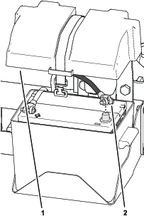
Remove the Negative Battery Cable
Remove the cover from the battery box and disconnect the negative-battery cable from the battery.
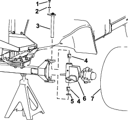
Removing the Hood
-
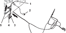
Remove the headlight connector of the machine wire harness from the connector of the headlight bulb (Figure 4).
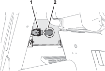
-
Repeat step 1 at the other headlight.
-
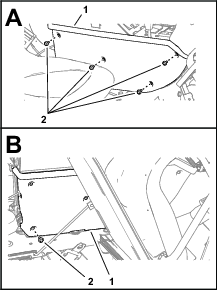
Remove the 4 push-in fasteners that secure the bottom flange of the hood to the machine (Figure 5).
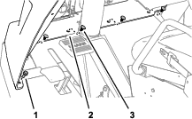
-
Remove the 2 flange-head bolts (5/16 x 3/4 inch) that secure the bottom flange to the machine (Figure 5).
-
Remove the 4 Phillips pan-head screws (1/4 x 1 inch) that secures the hood to the dash support (Figure 6).
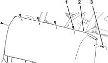
-
Remove the 2 push-in fasteners that secure the hood to the dash support (Figure 6).
-
Remove the hood from the machine (Figure 7).
Note: Retain the hood, 2 flange-head bolts, and 4 Phillips pan-head screws.

Removing the Heat Shield and Undercarriage Shroud
If equipped, remove the heat shield and shroud from the bottom of the machine; refer to the Operator’s Manual for your machine.
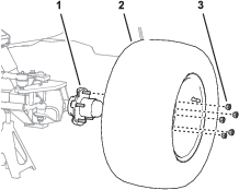
Removing the Left, Front Wheel
-
Lift the machine and support it with jack stands; refer to the Operator’s Manual for your machine.
-
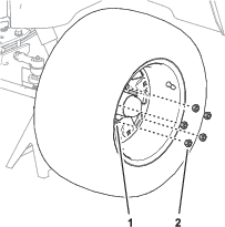
Remove the 5 wheel nuts that secure the left tire and wheel to the wheel hub, and remove the wheel from the machine (Figure 8).
Installing the Wheel Angle Sensor Shim
Parts needed for this procedure:
| Shim | 1 |
-
Install the shim into the wheel hub/spindle assembly.
-
Install the wheel hub/spindle assembly and king pin.
Installing the Wheel Angle Sensor (WAS)
Parts needed for this procedure:
| Wheel angle sensor (WAS; magnetic target and sensor) | 1 |
| Jam nut (10 mm) | 1 |
| Sensor bracket | 1 |
| Sensor alignment tool | 1 |
| Pan-head screw (#4 x 3/4 inch) | 2 |
| Locknut (#4) | 2 |
| Flange-head capscrew (1/4 x 3/4 inch) | 2 |
| Locknut (1/4 inch) | 2 |
Installing the Sensor Bracket
-
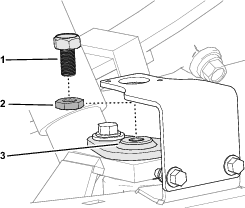
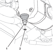
Remove the capscrew from the end of the kingpin (Figure 10).
Note: Discard the capscrew.
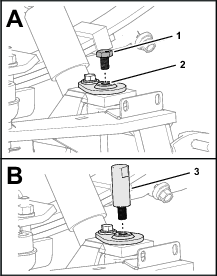
-
Thread the alignment tool into the top of the king pin (Figure 10).
-
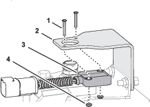
Align the sensor bracket over the alignment tool and the slots in the flange of the spindle (Figure 11).
-
Loosely assemble the bracket to the flange (Figure 11) with 2 flange-head capscrews (1/4 x 3/4 inch) and 2 locknuts (1/4 inch).
-
Position the bracket to the bottom of the slots in the flange of the spindle, and tighten the flange-head capscrews and locknuts (Figure 11).
-
Remove the alignment tool (Figure 12).

Assembling the Wheel Angle Sensor (WAS)
-
Fully thread the jam nut onto the WAS.
-
Thread the WAS into the top of the king pin.
-
Assemble the steering position sensor to the sensor bracket with 2 pan-head screws (#4 x 3/4 inch) and locknuts (#4), and tighten the screws and locknuts.
Adjusting the WAS
-
Adjust the position of the WAS until you measure a gap 4 mm (0.16 inch) between the target and the face of sensor (Figure 15).

-
Rotate the WAS until the indicator line that is stamped into the flat face of the WAS aligns with the wiring port of the sensor (Figure 15).
-
Tighten the jam nut (Figure 15).
-
Measure the gap between the target and the face of sensor (Figure 15). You should measure 2 to 4 mm (0.08 to 0.16 inch).
Note: If the gap is smaller than 2 mm (0.08 inch) or larger than 4 mm (0.16 inch)—adjust the position of the WAS, align the indicator line, and tighten the jam nut.
Installing the Wheel
Removing the Steering Valve Hoses
Parts needed for this procedure:
| Cap | 1 |
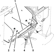
Removing the Hose Support Clamps
-
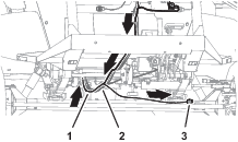
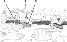
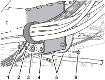
Under the floor plate, remove the nut (1/4 inch), lock washer (1/4 inch), washer (3/8 x 7/8 inch), and capscrew (1/4 x 7/8 inch) that secure the clamp supporting the hydraulic hoses to the clutch plate, and remove the clamp (Figure 17).
-
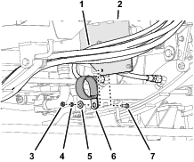
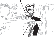
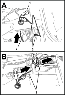
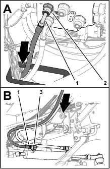
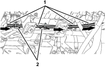
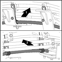
At the right side of the machine, remove the flange locknuts (5/16 inch), carriage bolt (5/16 x 1 inch), and carriage bolt (5/16 x 1-1/2 inches) that secure the 2 clamps supporting the return hose of the steering valve to the engine mounts, and remove the clamps (Figure 18).

-
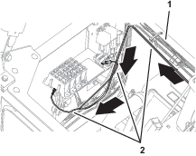
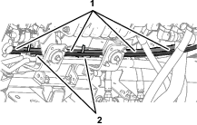
Remove the 2 flange locknuts (5/16) securing the 2 upper tube-clamp halves as shown in Figure 19, and remove the clamp halves.

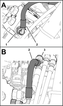
Removing the Return Hose for the Steering Valve
Removing the Pressure Hose for the Steering Valve
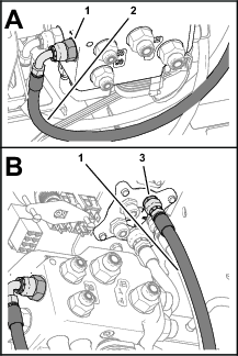
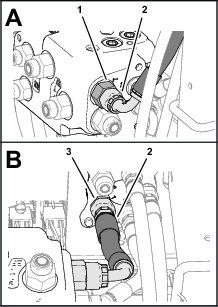
-
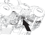
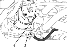
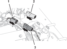
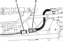
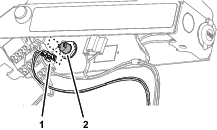
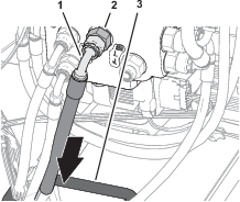
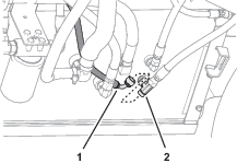
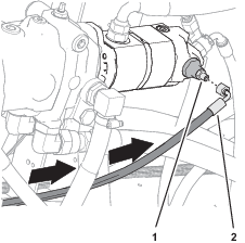
Disconnect the pressure hose for the steering valve from the T-fitting at the end of the hydraulic pump.

-
Remove the pressure hose from the machine.
Note: Discard the pressure hose.

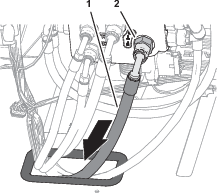
Removing the Load Sense Hose
-
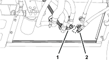
Disconnect the load-sense hose for the steering valve from the straight fitting at the bottom of the hydraulic pump.
Removing the Steering Cylinder Hoses
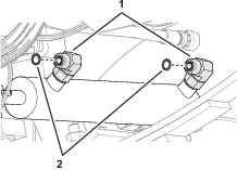
-
Disconnect the steering-cylinder hoses from the 90° fittings in the extend and retract ports of the steering cylinder (Figure 27).
-
Remove the steering-cylinder hoses from the machine.
Note: Discard the steering-cylinder hoses.
Installing the EHI Steering Valve
Parts needed for this procedure:
| Manifold mount | 1 |
| Flange-head capscrew (1/4 x 1/2 inch) | 2 |
| Washer (1/4 inch) | 2 |
| Flange locknut (1/4 inch) | 2 |
| U-bolt (3/8 inch) | 2 |
| Flange locknut (3/8 inch) | 4 |
| Model/serial decal | 1 |
| EHI steering valve | 1 |
| Straight hydraulic fitting (-6 x 12 mm) | 2 |
| Straight hydraulic fitting (-8 x 22 mm) | 4 |
| Straight hydraulic fitting (-6 x 18 mm) | 4 |
| Flange-head capscrew (8 x 16 mm) | 3 |
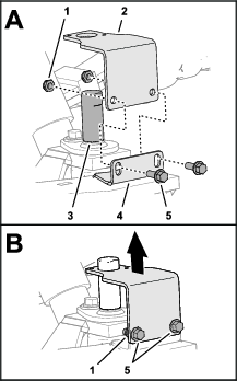
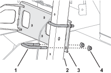
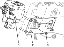
Installing the Manifold Mount
-
Align the manifold mount to the front of the machine as shown in Figure 28.
-
Align the holes in the manifold mount with the slots in the flange of the storage compartment (Figure 29).
Note: Ensure that the wires harness is not pinched between the mount and the compartment.
-
Loosely assemble the manifold mount to the flange (Figure 29) with 2 flange-head capscrews (1/4 x 1/2 inch), 2 washers (1/4 inch), and 2 flange locknuts (1/4 inch).
-
Loosely assemble the manifold mount to the dash support tube (Figure 30) with 2 U-bolts (3/8 inch) and 4 flange locknuts (3/8 inch).
-
Tighten the capscrews, U-bolts, and locknuts.
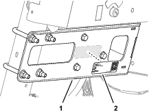
Affixing the Model/Serial Decal
-
Remove the backing from the model/serial decal.
-
Affix the decal to the manifold mount as shown in Figure 31.
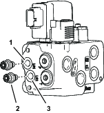
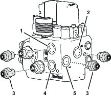
Preparing the EHI Steering Valve
-
Assemble 2 straight hydraulic fittings (-6 x 12 mm) into the EHI steering valve (Figure 32) as follows:
-
Port LS1
-
Port LS2
-
-
Remove the 2 plugs from port P and port T of the EHI steering valve (Figure 33).
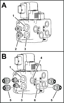
-
Assemble 4 straight hydraulic fittings (-6 x 22 mm) into the valve (Figure 33) as follows:
-
Port P
-
Port T
-
Port P (EF)
-
Port T (EF)
-
-
Assemble 4 straight hydraulic fittings (-6 x 18 mm) into the EHI steering valve (Figure 34) as follows:
-
Port CR
-
Port R
-
Port CL
-
Port L
-
Drilling the Console Base
Parts needed for this procedure:
| Grommet | 1 |
-
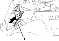
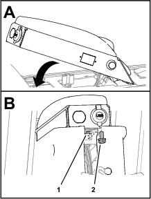
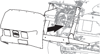
Tilt the passenger seat forward to access the console base (Figure 36).
-
Align a piece of sheet metal, approximately 120 mm (4 inches) wide, through the prop-rod slot in the console base, between the base and the wire harness below it.
Note: The sheet metal protects the wire harness when you drill through the console base.
-
Measure 69 mm (2-11/16 inches) rearward from the square hole near the prop-rod slot in the console base, and mark the console base (Figure 37).

-
Measure 45 mm (1-3/46 inches) inward from the slotted flange of console base, and mark the console base (Figure 37).
-
Center punch the console base at the intersection of the marks.
-
Drill a hole in the console base at the centerpunch mark with a 32 mm (1-1/4 inches) drill bit (Figure 37).
-
Remove the sheet piece of sheet metal, and remove any burrs around the hole.
-
Install the grommet into the hole (Figure 38).

Installing the Electrical Harness
Parts needed for this procedure:
| 2-position switch | 1 |
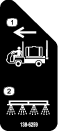
| Transport decal | 1 |
| Wire harness | 1 |
| Cable tie | 7 |
| Fuse (10 A) | 1 |
| Push-button switch, jam nut, and lock washer | 1 |
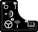
| AutoSteer remote-engage decal | 1 |
Assembling the Road Switch to the Dash
-
Remove the plug in the dash panel as shown in Figure 39.
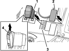
-
Align the 2-position switch with the shoulder of the switch (Figure 39) aligned to the top of the dash panel.
-
Insert the 2-position switch into the hole in the dash panel (Figure 39).
-
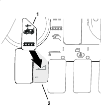
Apply the transport decal over the dash decal as shown in Figure 40.
Routing the Wire Harness at the Dash
-
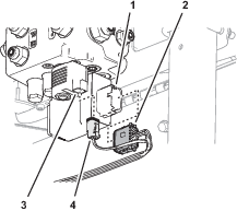
At the front of the machine, route the wire-harness connectors (Figure 44) with the following labels through the bottom of the floor plate:
-
Plug the 12-socket wire-harness connector labeled into the 12-pin connector of the EHI steering-valve (Figure 45).
-
Plug the 2-socket wire-harness connector labeled into the 2-pin connector of the EHI-solenoid (Figure 45).
-
Remove the cap from the 4-socket connector GeoLink wire harness labeled (Figure 46).
-
Plug the 4-pin connector of the kit wire harness labeled into the 4-socket connector labeled (Figure 46).
-
Plug the 8-socket connector of the kit wire harness labeled (Figure 47) into the 2-position switch that you installed in Assembling the Road Switch to the Dash.

Routing the Wire Harness Under the Operator’s Platform
-
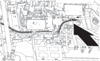
Route the wire harness for the kit rearward, along the wire harness for the machine (Figure 48).
-
Route the wire harness branch with the connector labeled along the back of the front axle tube (Figure 48).
-
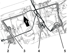
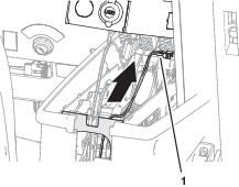
At the bottom, back side of the radiator, route the wire harness up, along the machine wire harness (Figure 49).
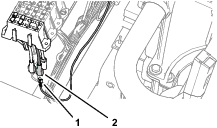
Connecting the Wheel Angle Sensor
-
Plug the 6-pin connector of the angle-sensor harness into the 6-socket connector of the kit wire harness labeled (Figure 50).
-
Secure the harness of the wheel angle sensor and the angle-sensor branch of the kit wire harness to the axle tube with 2 cable ties.
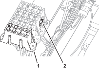
Connecting the Wire Harness to the Ground Block and Fuse Block
-
Route the wire harness branch with the terminals labeled and across the top of the radiator, along the machine wire harness (Figure 51).

-
Remove a terminal screw from the ground block (Figure 52).
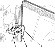
-
Assemble the ring terminal of the kit wire harness labeled to the ground block with the terminal screw (Figure 52).
-
Plug the terminal of the kit wire harness labeled into the blade connector for options power of the fuse block (Figure 53).
Note: If the fuse block of your machine does not have an available options-power circuit, install an additional options-fuse block; refer to your authorized Toro distributor.
-
Insert the fuse (10 A) into the fuse-block socket (Figure 54) for the options power circuit that you used in step 4.
-
Secure the switched power and ground branch of the kit wire harness to the machine wire harness with 4 cable ties.
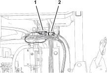
Connecting the Remote Engage Connectors
Plug the 2-pin connector of the kit wire harness labeled into the 2-socket connector of the GeoLink wire harness labeled (Figure 55).
Removing the Armrest
-
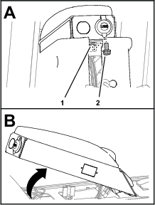
Remove 4 flange-head capscrews (1/4 x 3/4 inch) that secure the side panel of the center console as shown in Figure 56.
-
Tilt the seat forward, and remove the lower rear flange-head capscrew (Figure 56).
-
Repeat steps 1 and 2 at the other side of the center console.
-
Remove the flange-head capscrew (5/16 x 5/8 inch) that secures the arm panel to the console frame (Figure 57).
-
Lift the arm panel from the frame (Figure 57).
Drilling a Hole in the Armrest
-
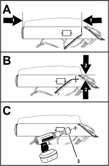
Measure 260 mm (10-1/4 inches) from the back end of the arm panel, and mark the panel (Figure 58).
-
Measure 35 mm (1-3/8 inches) from the top of the arm panel, and mark the panel (Figure 58).
-
Center punch the intersection of the marks.
-
Protect the wire in the arm panel.
-
Drill a 17 mm (11/16 inch) hole in the arm panel at the centerpunch mark (Figure 58).
-
Remove any burrs from the hole.
Assembling the Push-Button Switch to the Armrest
Routing the Wire Harness to the Remote Engage Switch
-
Route the wire harness branch labeled REMOTE ENGAGE SWITCH through the grommet (Figure 60) that you installed in Drilling the Console Base.
-
Route the wire harness branch labeled REMOTE ENGAGE SWITCH) into the center console (Figure 60).
-
Route the wire harness branch labeled REMOTE ENGAGE SWITCH) toward the arm panel (Figure 61).
-
Assemble the terminals of the wire harness branch labeled REMOTE ENGAGE SWITCH) onto the terminals of the push-button switch (Figure 62).
-
Secure the wire harness branch to the machine wire harness with a cable tie.
Assembling the Arm Panel to the Console Frame
-
Align the tabs at the front of the arm panel with the slots in the console frame, and rotate the arm pane down (Figure 63).
-
Secure the arm panel to the console frame (Figure 63) with the flange-head capscrew (5/16 x 5/8 inch).
-
Assemble the side panel to the console frame (Figure 64) with 4 flange-head capscrews (1/4 x 3/4 inch).
-
Tilt the seat forward and install the lower rear flange-head capscrew (Figure 64).
-
Repeat steps 3 and 4 at the other side of the center console.
-
Affix the AutoSteer remote-engage decal to the arm panel as shown in Figure 65.

Replacing the Steering Valve O-rings
Parts needed for this procedure:
| O-ring 9.2/1.8 mm (0.364/0.070 inch) | 3 |
| O-ring 7.6/1.8 mm (0.301/0.070 inch) | 2 |
-
Remove the 3 O-rings from the face of the -6 fittings of the steering valve.
Note: Discard the O-ring.
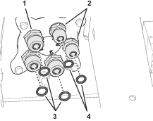
-
Install a 3 new O-ring 9.2/1.8 mm (0.364/0.070 inch) into the grooves of the -6 fittings.
-
Remove the 2 O-rings from the face of the -4 fittings of the steering valve.
Note: Discard the O-ring.
-
Install a 2 new O-ring 7.6/1.8 mm (0.301/0.070 inch) into the grooves of the -4 fittings.
Installing the Hoses
Parts needed for this procedure:
| Hose 6 x 203 mm (1/4 x 8 inches); -6 (straight) and -6 (45°) fittings | 1 |
| O-ring 12.4/1.8 mm (0.489/0.070 inch) | 2 |
| Hose 6 x 2819 mm (1/4 x 111 inches); -4 (90°) and -6 (90°) fittings | 1 |
| Hose 6 x 673 mm (1/4 x 26-1/2 inches); -4 (straight) and -6 (90°) fittings | 1 |
| Hose 6 x 711 mm (1/4 x 28 inches); -4 (straight) and -6 (90°) fittings | 1 |
| Hose 10 x 187 mm (3/8 x 7-3/8 inches); -6 (straight) and -8 (90°) fittings | 1 |
| Hose 10 x 264 mm (3/8 x 10-3/8 inches); -8 (90°) and -6 (45°) fittings | 1 |
| O-ring 9.2/1.8 mm (0.364/0.070 inch) | 2 |
| Hose 6 x 1397 mm (1/4 x 55 inches); -6 (straight) and -6 (90°) fittings | 1 |
| Hose 6 x 1270 mm (1/4 x 50 inches); -6 (straight) and -6 (90°) fittings | 1 |
| Hose 10 x 2921 mm (3/8 x 115 inches); -8 (90°) and -8 (90°) fittings | 1 |
| O-ring 7.6/1.8 mm (0.301/0.070 inch) | 1 |
| Cable tie | 3 |
Installing the Steering Valve Hoses
-
Assemble the 45° fitting of the hose 6 x 203 mm (1/4 x 8 inches) onto the port LS2 fitting of the EHI steering valve (Figure 67).
-
Assemble the straight fitting of the hose 6 x 203 mm (1/4 x 8 inches) onto the port E fitting of the steering valve, and tighten both hose fittings (Figure 67).
-
Route the end of the hydraulic pump hose 6 x 2819 mm (1/4 x 111 inches) with the -4, 90° fitting through the grommet in the floor plate (Figure 68).
-
Assemble the -6, 90° fitting of the hose 6 x 2819 mm (1/4 x 111 inches) onto the port the LS1 fitting of the EHI steering valve, and tighten the hose fitting (Figure 68).
-
Assemble the 90° fitting of the hose 6 x 673 mm (1/4 x 26-1/2 inches) into the port R fitting of the EHI steering valve (Figure 69).
-
Assemble the straight fitting of the hose 6 x 673 mm (1/4 x 26-1/2 inches) into the port R fitting of the steering valve, and tighten both hose fittings (Figure 69).
-
Assemble the 90° fitting of the hose 6 x 711 mm (1/4 x 28 inches) onto the port L fitting of the EHI steering valve (Figure 70).
-
Assemble the straight fitting of the hose 6 x 711 mm (1/4 x 28 inches) onto the port L fitting of the steering valve, and tighten both hose fittings (Figure 70).
-
Assemble the 90° fitting of the hose 10 x 187 mm (3/8 x 7-3/8 inches) onto the port T fitting of the EHI steering valve (Figure 71).
-
Assemble the straight fitting of the hose 10 x 187 mm (3/8 x 7-3/8 inches) onto the port T fitting of the steering valve, and tighten both hose fittings (Figure 71).
-
Assemble the 90° fitting of the hose 10 x 264 mm (3/8 x 10-3/8 inches) onto the port P fitting of the EHI steering valve (Figure 72).
-
Assemble the 45° fitting of the hose 10 x 264 mm (3/8 x 10-3/8 inches) onto the port P fitting of the steering valve, and tighten both hose fittings (Figure 72).
Installing the Steering Cylinder Hoses
-
Route the end of the hose 6 x 1397 mm (1/4 x 55 inches) with the straight fitting through the grommet in the floor plate (Figure 73).

-
Assemble the 90° fitting of the hose 6 x 1397 mm (1/4 x 55 inches) onto the port CR fitting of the EHI steering valve (Figure 73).
-
Remove the 2 O-ring in the face 90° fittings in the extend and retract ports of the steering cylinder (Figure 74).
Note: Discard the O-ring.
-
Install a 2 new O-ring 9.2/1.8 mm (0.364/0.070 inch) into the groove of the 90° fittings (Figure 74).
-
Assemble the straight fitting of the hose 6 x 1397 mm (1/4 x 55 inches) onto the 90° fitting in the retract port of the steering cylinder, and tighten both hose fittings (Figure 73).
-
Route the end of the hose 6 x 1270 mm (1/4 x 50 inches) with the straight fitting through the grommet in the floor plate (Figure 75).
-
Assemble the 90° fitting of the hose 6 x 1270 mm (1/4 x 50 inches) onto the port CL fitting of the EHI steering valve (Figure 75).
-
Assemble the straight fitting of the hose 6 x 1270 mm (1/4 x 50 inches) onto the 90° fitting in the extend port of the steering cylinder, and tighten both hose fittings (Figure 75).
Assembling the Tank-Return Hose and Hydraulic-Pump Hose to the EHI Steering Valve
-
Identify the tank-return hose 10 x 2921 mm (3/8 x 115 inches) with 2 fittings (90°).
-
Route the end of the tank-return hose 10 x 2921 mm (3/8 x 115 inches) through the grommet in the floor plate (Figure 76).
-
Assemble the 90° fitting of the tank-return hose 10 x 2921 mm (3/8 x 115 inches) onto the port EF fitting of the EHI steering valve, and tighten the hose fitting (Figure 76).
-
Identify the hydraulic-pump hose 10 x 2921 mm (3/8 x 115 inches) with a 90° fitting and a 45° fitting.
-
Route the end of the hydraulic-pump hose 10 x 2921 mm (3/8 x 115 inches) with the 45° fitting the through the grommet in the floor plate (Figure 77).
-
Assemble the 90° fitting of the hydraulic-pump hose 10 x 2921 mm (3/8 x 115 inches) onto the port PT fitting of the EHI steering valve, and tighten the hose fitting (Figure 77).
-
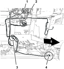
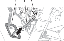
Route the 2 hydraulic pump hoses and the tank-return hose rearward, along the right frame tube of the machine (Figure 78).
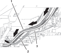
Routing the Hydraulic Pump Hoses
-
Route the hydraulic pump hose 10 x 2921 mm (3/8 x 115 inches—EHI steering valve port PT) with the 45° fitting into the top groove of the tube-clamp half at the upper location (Figure 79).
-
Route the 45° fitting of the hose toward the hydraulic pump.
-
Route the hydraulic pump hose 6 x 2819 mm (1/4 x 111 inches—EHI steering valve port LS1) with the 90° fitting into the bottom groove of the tube-clamp half at the upper location (Figure 80).
-
Route the 90° fitting of the hose toward the hydraulic pump.
-
Assemble the 2 tube-clamp halves onto the capscrews, and secure the tube-clamp halves and hoses (Figure 81) with 2 flange-head locknuts (5/16 inch).
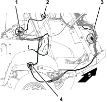
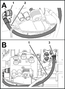
Installing the Hydraulic Tank Return Hose
-
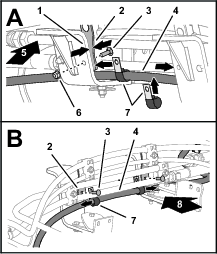
Route the tank-return hose 6 x 2819 mm (1/4 x 111 inches—EHI steering valve port EF) across the top of the right engine mount brackets (Figure 82).
-
Assemble the 2 P-clamps onto the hose as shown in Figure 82.
-
Align the 2 P-clamps between the tube clamp mount plates and the engine mount brackets (Figure 82).
-
Secure the clamp mount plates and P-clamps to the engine mount brackets (Figure 82 and Figure 83) with the 2 carriage bolt (5/16 x 1 inch) and 2 flange locknut (5/16 inch).
-
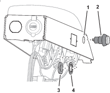
Remove the O-ring in the face of the T-fitting of the hydraulic tank (Figure 84).
Note: Discard the O-ring.

-
Install a new O-ring 12.4/1.8 mm (0.489/0.070 inch) into the groove of the T-fitting (Figure 84).
-
Assemble the 90° fitting of the tank-return hose 6 x 2819 mm (1/4 x 111 inches) onto the T-fitting, and tighten the hose fitting (Figure 85).
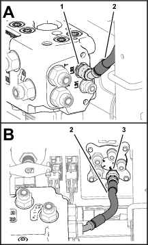
Installing the Hydraulic Pump Hoses
-
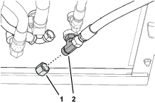
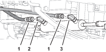
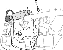
Remove the O-ring in the face of the T-fitting at the end the hydraulic pump (Figure 86).
Note: Discard the O-ring.
-
Install a new O-ring 12.4/1.8 mm (0.489/0.070 inch) into the groove of the T-fitting (Figure 86).
-
Assemble the 45° fitting of the hose 10 x 2921 mm (3/8 x 115 inches) onto the T-fitting, and tighten the hose fitting (Figure 87).
-
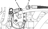
Remove the O-ring in the face of the straight fitting at the end of the hydraulic pump (Figure 88).
Note: Discard the O-ring.
-
Install a new O-ring 7.6/1.8 mm (0.301/0.070 inch) into the groove of the straight fitting (Figure 88).
-
Assemble the 90° fitting of the hose 6 x 2819 mm (1/4 x 111 inches) onto the straight fitting, and tighten the hose fitting (Figure 89).
Installing the Lower Hose Cover
-
Under the floor plate, secure the hoses and wire harnesses to the clutch and clutch plate as shown in Figure 90 with the support clamp, capscrew (1/4 x 7/8 inch), nut (1/4 inch), lock washer (1/4 inch), and washer (3/8 x 7/8 inch) that you removed in Removing the Hose Support Clamps.
-
Assemble the lower hose cover over the steering hoses (Figure 91).

-
Secure the cover to the hoses with 3 cable ties (Figure 91).
Installing the Negative Battery Cable
Purging Air from the Hydraulic System
-
Start the engine.
-
Fully turn the steering wheel left and right until the wheel turns smoothly.
-
Shut off the engine and remove the key.
Checking for Hydraulic Leaks
-
Check the hoses and fittings at the EHI steering valve and the steering valve for hydraulic leaks.
Important: Fix all leaks before installing the hood.
-
Check the hoses and fittings at the hydraulic tank and hydraulic pump for leaks.
Important: Fix all leaks.
Installing the Hood
Parts needed for this procedure:
| Push-in fasteners | 6 |
-
Align the holes in the hood with the holes in the chassis of the machine (Figure 93).
-
Assemble the hood to the dash support with 2 push-in fasteners (Figure 94).
-
Secure the hood to the dash support (Figure 94) with 4 Phillips pan-head screws (1/4 x 1 inch).
-
Assemble the bottom flange of the hood to the machine with 4 push-in fasteners (Figure 95).
-
Secure the flange to the machine (Figure 95) with 2 flange-head bolts (5/16 x 3/4 inch).
-
Assemble the headlight connector of the machine wire harness to the connector of the headlight bulb (Figure 96).
-
Repeat step 6 at the other headlight.
Installing the Heat Shield and Undercarriage Shroud
If removed, installed the heat shield and undercarriage shroud to the bottom of the machine; refer to the Operator’s Manual for your machine.
Checking the Hydraulic Fluid Level
Check the hydraulic fluid level. If the fluid level is low, add fluid to the hydraulic tank; refer to the Operator’s Manual for the hydraulic fluid specification and checking procedure.
Verifying the Software Version
-
Turn the ignition key to the RUN(gasoline) or PREHEAT/RUN (diesel) position.
-
Press the ABOUT (Toro) icon at the upper left corner of the control console (Figure 97).

-
When the software version is correct, the About dialog box displays software version 4.04 or higher.
Note: If the software versions differ, contact the Toro technical assistance center.
Verifying the Minimum Hardware Requirements
Ensure that your laptop computer that meets the hardware, operating system, and application requirements before installing the Danfoss PLUS+1® Service Tool; refer to the tables that follow.
|
Component |
Minimum Capacity |
|---|---|
|
CPU* |
1.5 GHz, 32–bit, 1 core, 2008 or later |
|
Memory |
1 GB |
|
Unused Hard Drive Space |
Greater than 1 GB |
|
Minimum Display Resolution |
1024 x 768 |
|
USB Port |
Version 2.0 or higher |
|
* The CPU must be intended for laptop use. Processors intended for netbooks, tablets, or similar devices are not recommended. |
|
|
Software |
Version |
|---|---|
|
Operating System Version |
Microsoft Windows 7—32 bit |
|
OS Components |
MSXML 4.0, Service Pack 2 (Microsoft XML Core Services) |
|
User Account Rights |
Local administrator access |
|
Software |
Notes |
|---|---|
|
Email Client/Reader |
For license registration. |
|
PDF Reader |
Any recent standards compliant reader. |
|
Web Browser |
Any recent standards compliant web browser (for HTML based F1 Help). |
Downloading the Software
Refer to the AutoSteer Software Guide.
Setting Up and Calibrating the Software
Calibrating the Compass
Ensure that the GeoLink compass is calibrated, refer to the GeoLink Software Guide for your machine.
Preparing to Calibrate the Machine
Installer provided equipment: a USB/CAN interface cable (Toro DIAG cable) Part No. 115-1944
-
Park the machine on the grass at a level location.
-
Shut off the engine and engage the parking brake.
Connecting the Laptop Computer to the Machine
-
If the Toro Diag application is running on the laptop computer, close the Toro Diag application.
Important: Do not begin the calibration process if the Toro Diag application is running on the laptop computer.
-
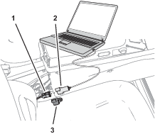
Plug the USB/CAN interface cable into a USB port of the laptop computer.
-
At the machine, rotate the key to the ON position.
-
Open the Plus+1 program.
-
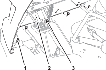
Remove the cap from the 3-socket connector of the kit wire harness CAN port labeled DUPLICATE DIAG CONNECTOR, and plug the 3-pin connector USB/CAN interface cable into the 3-socket connector.
-
On the dash panel of the machine, press enable/transport switch to the ENABLE MODE position.
-
In the System Navigator tab, navigate to the AUTO CALIBRATION directory, expand the directory, and click on WAS Calibration.
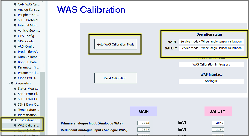
-
Click GOTO WAS CALIBRATION MODE button.
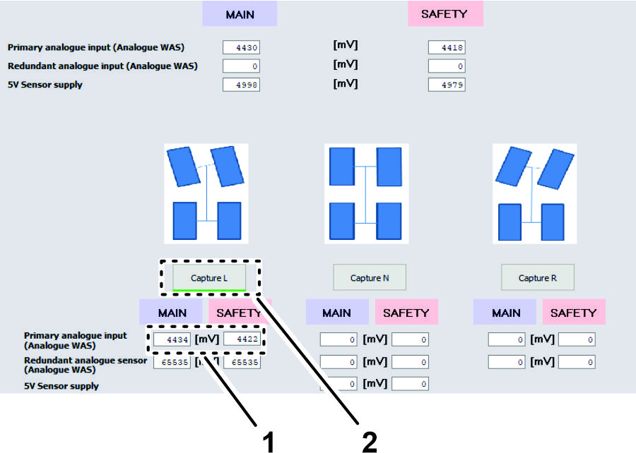
Capturing Steering Values
-
Start the engine of the machine.
-
Fully turn the steering wheel to the left and stop.
-
Click the CAPTURE L button.
Note: The sensor value changes as you turn the steering wheel.
-
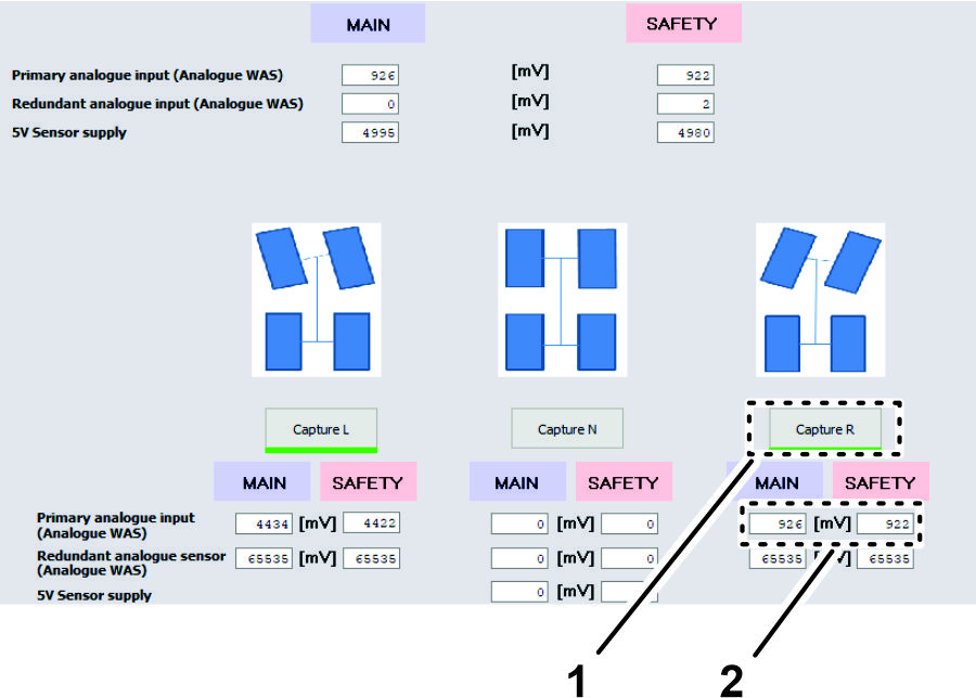
Fully turn the steering wheel to the right and stop.
-
Click the CAPTURE R button.
Note: The sensor value changes as you turn the steering wheel.
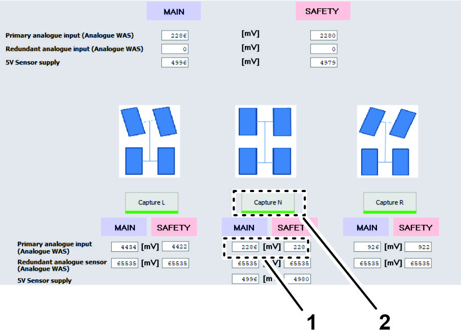
-
Turn the steering wheel until the tires align straight ahead and stop.
-
Click the CAPTURE N button.
Note: The sensor value changes as you turn the steering wheel.
Verifying / Checking the WAS Calibration Values
-
Ensure that your values are within the minimum and maximum ranges as listed.
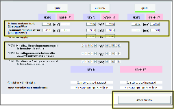
-
Click the ACCEPT AND SAVE button.
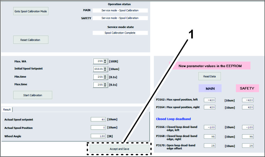
Running Spool Calibration Process
-
Turn the steering wheel as needed to position the front tires straight ahead.
-
In the System Navigator tab, navigate to the AUTO CALIBRATION directory, expand the directory, and click on SPOOL CALIBRATION.

-
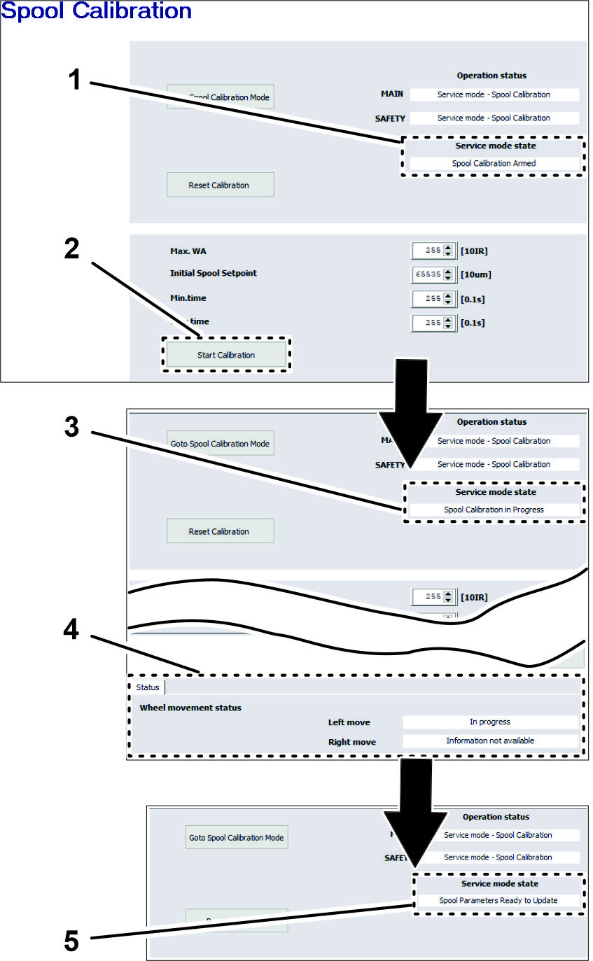
On the spool calibration page, click the GOTO SPOOL CALIBRATION MODE button.
-
Click the START CALIBRATION button.
Note: The service mode state must display Spool Calibration Armed before starting calibration.
Important: Do not touch the steering wheel.
The steering wheel moves while spool calibrations proceeds. The spool calibration process takes several minutes. Note that the wheel movement status changes in Status tab. Calibration is finished when Service Mode State field displays SPOOL PARAMETERS READY TO UPDATE.
-
At the bottom of the spool calibration screen, click the ACCEPT AND SAVE icon (Figure 106).
-
Shut off the engine.
-
Remove the connector of the USB/CAN interface cable from the connector of the kit wire harness, and install the cap onto the wire harness connector.
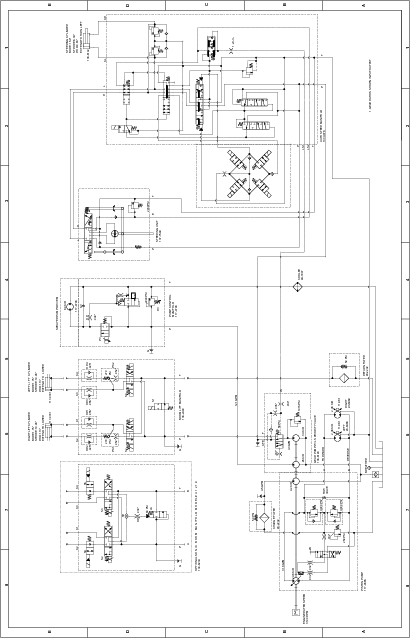
Schematics
Hydraulic Schematic 138-6255