Installation
Preparing the Machine
-
Park the machine on a level surface.
-
Ensure that the parking brake is engaged; refer to your Operator's Manual.
-
Lower the cutting unit (if equipped).
-
Shut off the machine and remove the key.
-
Turn the battery-disconnect switch to the OFF position.
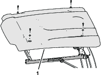
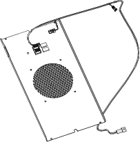
Removing the Sunshade
Preparing the Switch Panel
Parts needed for this procedure:
| Decal | 1 |
| Switch panel | 1 |
| Plug | 4 |
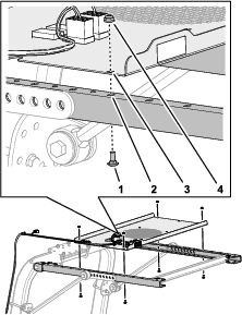
Installing the Decal to the Switch Panel
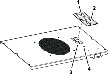
Installing the Switch Panel to the Sunshade Frame
Parts needed for this procedure:
| Sunshade wire harness | 1 |
| Carriage bolt | 4 |
| Nut | 4 |
| Cable tie | 6 |
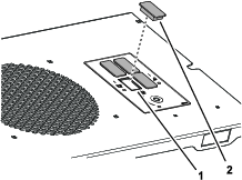
Aligning the Sunshade Wire Harness to the Switch Panel
Align the sunshade wire harness to the switch panel as shown in Figure 5.
Assembling the Switch Panel to the Sunshade Frame
Routing the Sunshade Wire Harness
-
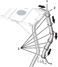
Route the sunshade wire harness along the roll-bar tube as shown in Figure 7.
-
Route the wire-harness end labeled P08 through the platform grommet (Figure 7).
-
For Groundsmaster e3300 machines: Perform the following steps to complete the wire-harness installation:
-
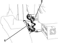
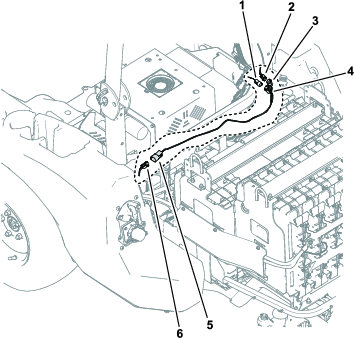
Raise the hood and install the kit wire-harness connector labeled to the machine wire-harness connector labeled .
Note: The P19 connector is located above the hydraulic-tank cap.
-
Secure the wire harness to the roll-bar tube with the cable ties as needed (Figure 7).
Note: The additional jumper wire harness is not needed for the Groundsmaster e3200.
-
-
For Groundsmaster e3200 machines: Refer to Installing the Jumper Wire Harness to complete the wire-harness installation.
Installing the Jumper Wire Harness
Parts needed for this procedure:
| Jumper wire harness | 1 |
-
Raise the hood and install the connector for the sunshade wire harness labeled to the connector for the jumper wire harness labeled (Figure 9).
-
Install the connector for the jumper wire harness labeled to the connector on the machine wire harness labeled (Figure 9).
-
Route the connector for the jumper wire harness labeled along the machine wire harness to the left side of the machine and install it to the connector labeled (Figure 9).
-
Secure the sunshade wire harness to the roll-bar tube with the cable ties as needed (Figure 7).
Installing the Sunshade
-
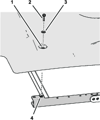
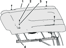
Align the holes in the grommets of the sunshade with the 4 clip nuts of the side-frame channels.
-
Assemble the sunshade to the frame channels (Figure 10) with the 4 flange-head bolts (5/16 x 1-1/4 inches) and 4 washers (5/16 inch) that you removed in Removing the Sunshade.
-
Torque the flange-head bolts to 1,017 to 1,355 N∙cm (90 to 120 in-lb).
Completing the Installation
Turn the battery-disconnect switch to the ON position.