Safety

Safety and Instructional Decals

Graphic

Safety decals and instructions are easily visible to the operator and are located near any area of potential danger. Replace any decal that is damaged or missing.

decal127-7388

Installation

Note: Determine the left and right sides of the machine from the normal operating position.

Preparing the Machine

  1. Park the machine on a level surface.

  2. Engage the parking brake.

  3. Shut off the engine and remove the key.

  4. Lift the lever on either side of the cargo bed and lift the bed up (Figure 1).

    g014860
  5. Pull the prop rod into the detent slot to secure the bed (Figure 2).

    Warning

    A raised bed could fall and injure persons that are working beneath it.

    • Always use the prop rod to hold the bed up before working under the bed.

    • Remove any load material from the bed before raising it.

    g029622
  6. Remove the 4 flange nuts securing the latch-rod brackets to the underside of the bed (Figure 3).

    g024927
  7. Remove and retain the latch rod and latches.

Installing the Bed-Lift Brackets

Parts needed for this procedure:

Outboard-lift bracket (short flanges)1
Inboard-lift bracket (long flanges)1
Hex-head bolt (5/16 x 5-1/2 inches)1
Flange nut (5/16 inch)1

Perform the bed bracket installation at the bottom side of the bed.

  1. Remove the 2 left-most bolts (5/16 x 3/4 inch) that secure upper-bed brace to the bed (Figure 4).

    g025008
  2. Remove the 2 left-most bolts (5/16 x 3/4 inch) that secure lower-bed brace to the bed (Figure 4).

    Note: Retain the 4 bolts for installation.

  3. Align the left outboard-lift bracket (the bracket with the short flanges) to the outboard holes in the upper- and lower-bed braces (Figure 5).

    g025009
  4. Secure the outboard lift bracket to the bed using the 2 bolts that you removed in step 1, and hand-tighten the bolts (Figure 5).

  5. Align the inboard-lift bracket (the bracket with the long flanges) to the inboard holes in the upper- and lower-bed braces (Figure 5).

  6. Secure the inboard-lift bracket to the bed with the 2 bolts that you removed in step 2, and hand-tighten the bolts (Figure 5).

  7. Insert the hex-head bolt (5/16 x 5-1/2 inches) through hole 8 mm (5/16 inch) in the inboard-lift bracket (long flanges), bed structure, and the outboard bed-lift bracket (short flanges) as shown in Figure 6.

    g025010
  8. Secure the bolt with the flange nut (5/16 inch) hand-tight (Figure 6).

Installing the Switch

Parts needed for this procedure:

Switch1
Fuse (15 A)—machine serial number 411599999 and before only1

Machine Serial Number 411599999 and Before

  1. Disconnect the negative-battery terminal from the battery.

  2. Remove the plug from the dash panel, to the right of the steering column and above the key switch (Figure 7).

    Note: If the hole in the dash is in use, measure over 13 mm (1/2 inch) and cut another 21 x 35 mm (27/32 x 1-15/32 inches) rectangular opening in the dash. Ensure that you do not damage any existing components behind the dash when cutting the hole.

    g001324
  3. Plug the bed-lift switch into the harness connector in the dash.

    Note: Do not install the switch.

  4. Trim the fuse tabs so they sit flush with the fuse block.

  5. Install the new fuse (15 A) into the open slot in the fuse block.

Machine Serial Number 411600000 and After

  1. Cut out the opening in the dashboard decal for the switch (box A of Figure 8).

  2. Install the switch connector through the opening in the dashboard (box B of Figure 8).

  3. Install the switch to the switch connector (box C of Figure 8).

  4. Ensure that the switch is oriented properly (box D of Figure 8).

g382366

Installing the Lift Actuator

Parts needed for this procedure:

Lift actuator1
Clevis pin (3-1/2 inches)1
Clevis pin (2-1/4 inches)1
Hairpin2
Hex-head bolt (1/2 x 5-1/2 inches)1
Locknut (1/2 inch)1
  1. Align the hole in the lower-mount point for the lift actuator with the holes in the chassis-mount brackets (Figure 9).

  2. Secure the lift actuator to the chassis-mount brackets with the clevis pin (2-1/4 inches) and hairpin (Figure 9).

    g024929
  3. Connect the 2-socket electrical connector of the rear wire harness of the machine to the 2-pin connector of the lift actuator (Figure 10).

    Note: The 2-socket electrical connector of the rear wire harness is located adjacent to the electrical-control cover.

    g025011
  4. Connect the negative-battery terminal to the battery.

  5. Press the up-paddle of the bed-lift switch to extend the actuator (Figure 7).

    Note: If the lift actuator does not extend, press the other paddle of the switch.

  6. Align the up-paddle to the 12 o’clock position and insert the bed-lift switch into the opening in the dash (Figure 7).

    Note: The switch should snap and lock into position.

  7. Press the up paddle the bed-lift switch to extend the rod of the lift actuator rod until the hole in the rod is aligns with the holes in the inboard and outboard-lift brackets (Figure 11).

    Note: Select the set of holes in the bracket for the gasoline and diesel machines; refer to for the hole locations for this machine.

    g025012
  8. Secure the lift-actuator rod to the lift brackets with the clevis pin (3-1/2 inches) and hairpin (Figure 11).

    Note: Tighten the locknut and flange nut until they are snug.

  9. Tighten the 4 bolts (5/16 x 3/4 inch) that secure the inboard and outboard-lift brackets to the bed (Figure 5) to 15 to 16.6 N-m (133 to 147 in-lb).

  10. Align the hex-head bolt (1/2 x 5-1/2 inches) through the remaining 12.7 mm (1/2 inch) holes in the inboard and outboard-lift brackets (Figure 11) and secure it with a locknut (1/2 inch) until the nut is snug.

  11. Tighten the flange nut that secures the bolt (5/16 inch) until it is snug (Figure 6).

Removing the Prop Rod

  1. Remove the hairpin and washer that secure the prop rod to the bottom of the bed (Figure 12).

    g025013
  2. Slide the prop rod forward to remove it from the bracket on the frame (Figure 12).

    Note: Retain the prop rod components for future use.

    Note: If the electric box lift is ever removed, install the prop rod and latch rod again, using the existing fasteners and the prop-rod bracket.

Operation

Warning

Driving the machine with the cargo bed raised could cause the machine to tip or roll easier. You could damage the structure of the cargo bed if you operate the machine with the bed raised.

  • Operate the machine when the cargo bed is down.

  • After emptying the cargo bed, lower it.

Warning

The weight of the bed may be heavy. Hands or other body parts could be crushed.

Keep your hands and other body parts clear when lowering the bed.

Important: When you hear a ratcheting sound, the bed lift is completely extended or retracted. Do not continue pressing the switch.

Raising the Bed

  1. Turn the key switch to the ON position.

  2. Push the top of the switch to raise the bed.

Lowering the Bed

Push the bottom of the switch to lower the bed.

Note: The actuator may cause slight deformation to the bed after it is fully lowered and before the actuator clutch engages. Release the switch when you hear a ratcheting noise.

Maintenance

Servicing the Air Cleaner

For Workman MDX-D Machines
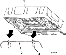
  1. Support the bed with lifting equipment.

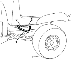
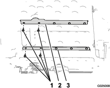
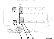
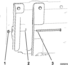
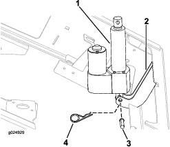
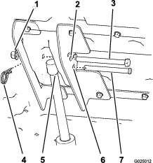
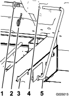
  2. Remove the hairpin cotter and clevis pin securing the actuator rod to the inboard and outboard-lift brackets (Figure 11).

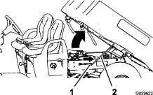
  3. Tip the bed all the way up.

  4. Rotate the actuator forward.

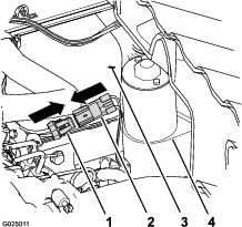
  5. Remove the air cleaner and service it as required; refer to the machine Operator’s Manual.

  6. Install the air cleaner; refer to the machine Operator’s Manual.

  7. Lower the bed and align the lift actuator to the lift brackets (Figure 11).

  8. Secure the lift actuator to the lift brackets with the clevis pin and hairpin (Figure 11).