 |
| CALIFORNIA |
| Proposition 65 |
| This product contains a chemical or chemicals known to the State of California to cause cancer, birth defects, or reproductive harm. |
 |
Warning | |
| Important |
| Model Number: |
Serial Number: |

|
Danger | |
|
Warning | |
|
Caution | |
| Important |
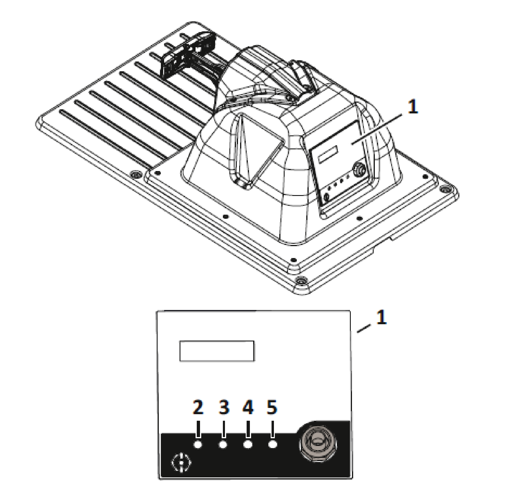
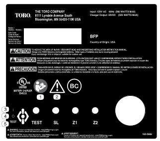
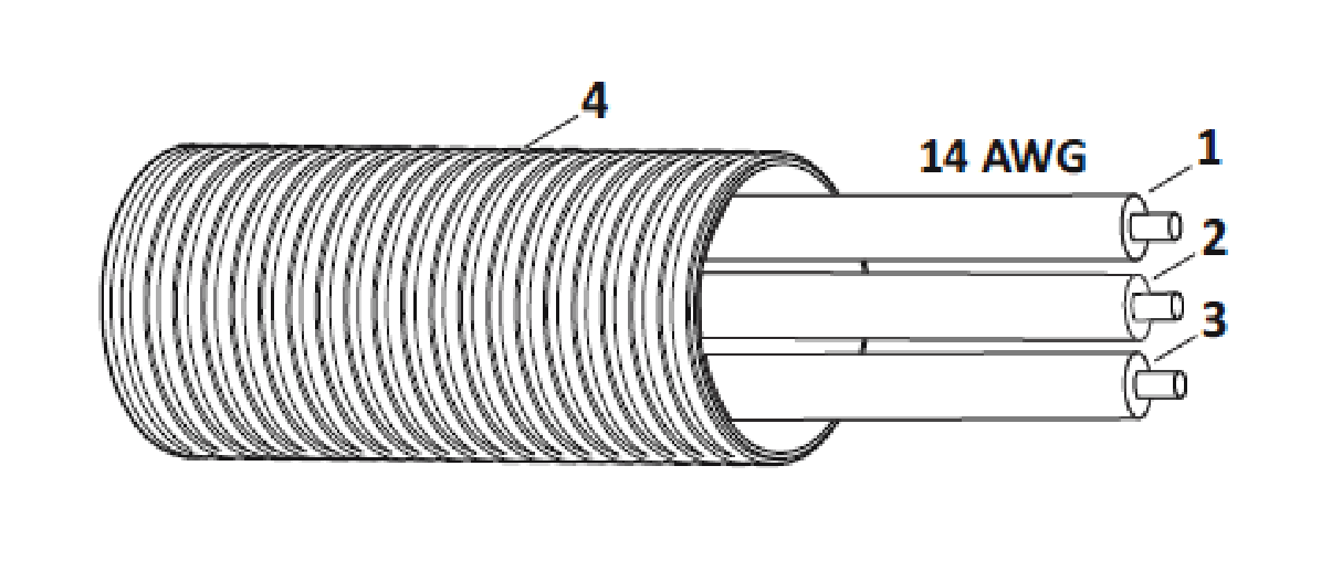
| TEST LED
|
Illuminates green when AC power
is present and the power switch is in the TEST position. |
| SL (Station Loop) LED |
Blinks green when the station
loop peripheral wire is correctly connected, blinks red when an issue
is detected. |
| Z1 (Field Zone 1) LED |
Blinks green when Field Zone 1
peripheral wire is correctly connected, blinks red when an issue is
detected. |
| Z2 (Field Zone 2) LED |
Blinks green when Field Zone 2
peripheral wire is correctly connected, blinks red when an issue is
detected. |
| Green - blinking
|
The wire is operating normally. |
| Red - blinking
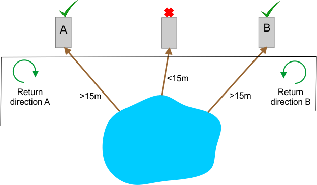
|
No peripheral wire can be detected.
This could be because the wire has been cut or that it is too long. |
| Red - steady
|
This indicates a problem. This
could be due to the wire being too short, less than 200 m (656 ft),
or there is a problem with the
electronics. |
| Length
|
993 mm (39.1 inches) |
| Width
|
646 mm (25.4 inches) |
| Height
|
356 mm (14 inches) |
| Operating Temperature |
0 to 50°C (32 to 122°F) |
| Input
|
120 VAC - 60 Hz 3.5 A (360 W maximum)
|
| Charge Outputs
|
32 VDC 10.7 A (320 W maximum) |
| Output Circuits
|
Class 2
|
| 1
|
Deep-well socket/driver (8 mm) |
| 1
|
Flat-blade screwdriver (3 mm) |
| 1
|
Phillips screwdriver (#1) |
| 1
|
Adjustable wrench |
| 1
|
Wire strippers
|
| 1
|
Tape measure
|
| 1
|
Hammer
|
| 1
|
Slip-joint pliers |
| 1
|
Driver (T-27) (supplied with charging
station) |
| Important |
| Important |
| Important |
| Important |
| Important |
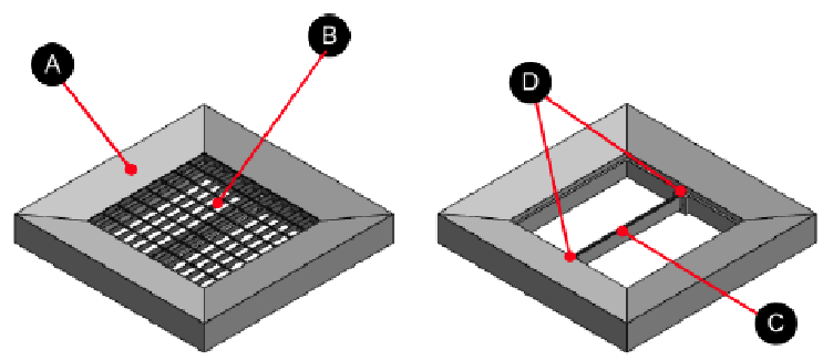
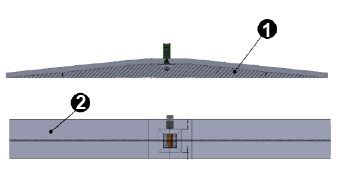
| Grating
|
800 x 800 x 30mm (31.5 x 31.5
x 1.2 inches) |
| Mesh size
|
66 x 99 mm (2.6 x 3.9 inches) |
| Steel thickness
|
3 mm (0.118 inches) |
| Finish
|
Galvanized
|
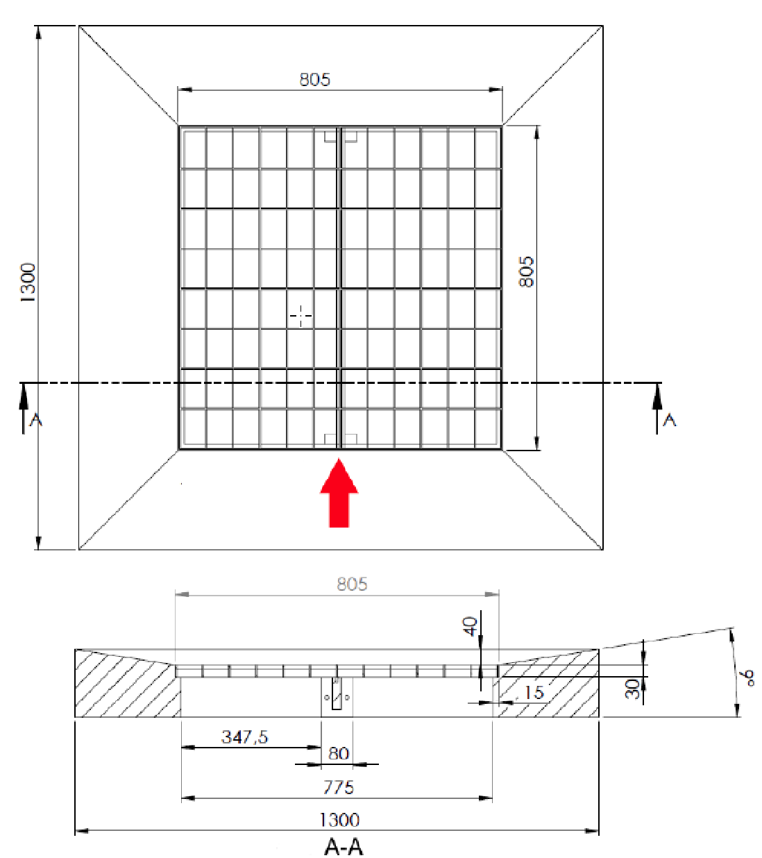
| 1,300 mm
|
51.18 inches
|
| 805 mm
|
31.7 inches
|
| 775 mm
|
30.5 inches
|
| 347.5 mm
|
13.68 inches
|
| 80 mm
|
3.15 inches
|
| 40 mm
|
1.57 inches
|
| 30 mm
|
1.18 inches
|
| 15 mm
|
0.6 inches
|