Product Overview
Overview of the RTK GPS
- Standard GPS positioning data
retrieved from satellites using GNSS (Global Navigation Satellite
System) is accurate to between 5m and 10m.
This is because the signal received from a satellite is distorted
due to atmospheric and environmental conditions.
Higher precision positioning can be achieved by using an
RTK (Real-Time Kinematic) technique.
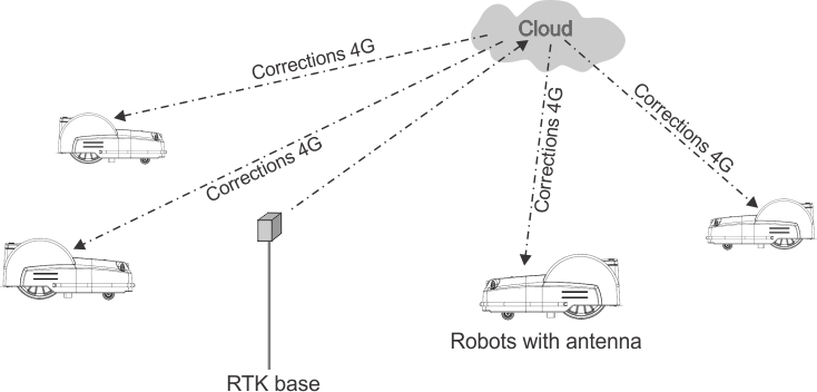
- This technique involves the use of an RTK base placed in a fixed
position, which receives GNSS signals from satellites. Since
the base is fixed, the data it receives relates
to its precise location.
- The robots are also fitted with
antennas, which receive GNSS signals from satellites in order to determine
their position. Both the RTK base and the
robots receive the GNSS signals from satellites in different constellations
(GPS, GLONASS, Galileo, BeiDou). Since
the robots are moving however, the evaluation of their position is
less precise that that of the fixed base.
- The RTK base computes correctional data for each of the satellites
and sends these to the robot. The robot is then able to
use these corrections to achieve a positional accuracy
of between 2cm and 3cm. With such accurate positioning, the robot
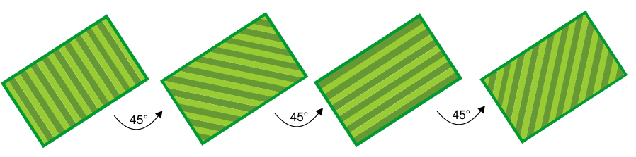
is able to follow a defined pattern and cover
the field in a series of straight lines.
Corrections
can also be made via the cloud using 4G. In this case, obstacles do
not impede the transfer of correctional data
and the base can connect to an unlimited number robots at distances
of up to 15km.
Transfer of corrections using
4G
G520851
One base station can feed corrections
to multiple robots, but each robot must receive corrections from only
1 base station to keep corrections consistent.
Basic components of the RTK GPS
mowing system
G520852
This topic describes the mechanical
characteristics of the robot.
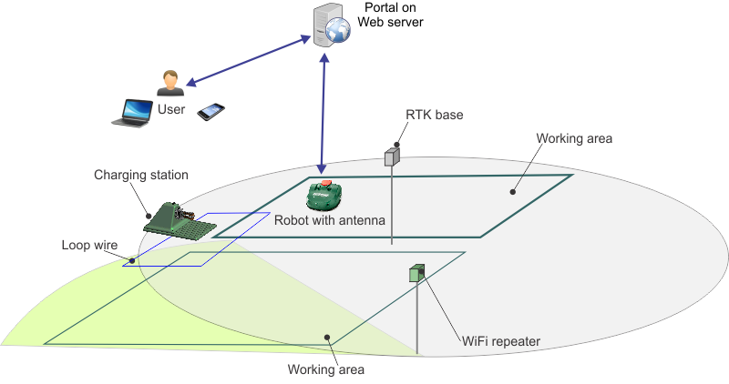
A user can exercise direct control
over the robot using the User Interface. Once a robot is registered
on the portal running on a web-server:
- The robot can send information
to this server which can be seen by the user.
- The user can issue commands to
the robot, assess its performance and adjust the configuration.
Turf Mower 500SL Product Overview
Top view
G519921
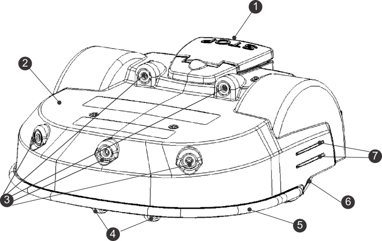
-
Stop button
-
Body
-
Obstacle detection sonars
-
Front wheels
-
Bumper
-
Rear wheels
-
Charge contacts
Bottom view
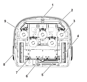
G529049
-
Coil
-
Front wheels
-
Cutting heads
-
Rear wheels
-
Battery
-
Sealed electronic box (smartbox)
-
ON/OFF switch
-
Charge contacts
-
Guard disc
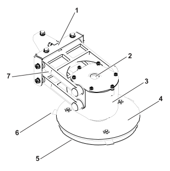
Cutting head
G526500
-
Bracket
-
Cable entry
-
Motor housing
-
Blade-support disc
-
Anti-friction disc
-
Cutting blade
-
Pantograph
Note: The blade support disc (D), the anti-friction disc (E) and the cutting
blades (F) are referred to collectively as the "cutting
disc".
Power switch
 |
The power switch is located under
the cover on the right-rear of the robot.
Move the power
switch up, to the ON position,
to operate the robot. Move the power switch down, to
the OFF position,
for extended idle time or winter storage.
|
RTK GPS antenna
G519918
This is a specific GNSS antenna
installed at center front of the shell. It is used to receive data
about the robot's global position from satellites.
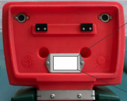
Identification label
The identification
label can be found on the inside of the Stop button lid as shown below.
G519938
Sensor Overview
The Turf Pro 500SL is equipped
with a comprehensive set of sensors that ensure its safe operation.
These sensors ensure that the robot can detect,
and react if an obstacle lies in its path or if a small object is
in danger of being damaged by the cutting
blades.
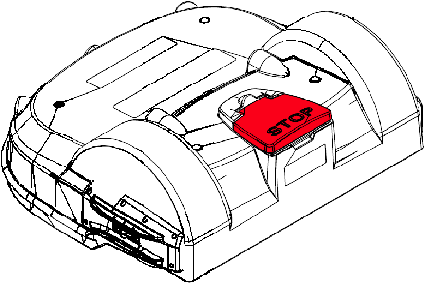
Stop Button
The stop button is easily
visible, situated on the top of the robot. Hitting this button will
cause the robot to stop moving and cutting.
The stop button also acts as a lid, which when lifted, provides access
to the robot's control user interface.
An instruction must be issued using this control interface in order
to restart the robot.
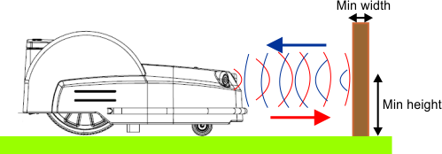
Obstacle Detection Sonars
The robot is equipped with a set
of sonar sensors to detect obstacles. These sensors transmit a constant
sonar signal (40kHz). When these hit an
obstacle the reflected waves are received by the sensors and the speed
of the robot is reduced to 200mm/s (less
than 1km/h).
Detection of obstacles by sonar
sensors
G525070
If the robot is always
moving at a slow speed, even if there are no obstacles in view, it
indicates a problem with the sensors. In
this case you should contact the after-sales team for help in analyzing
the problem.
Bumper
The
bumper is a pressure sensor which senses when the robot touches an
obstacle. The robot will be moving at a slow speed
because the sonar detectors will have already detected
the obstacle. When the bumper touches the obstacle, the robot will
move backwards and then rotate through
an angle until it can avoid the obstacle.
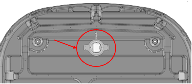
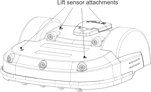
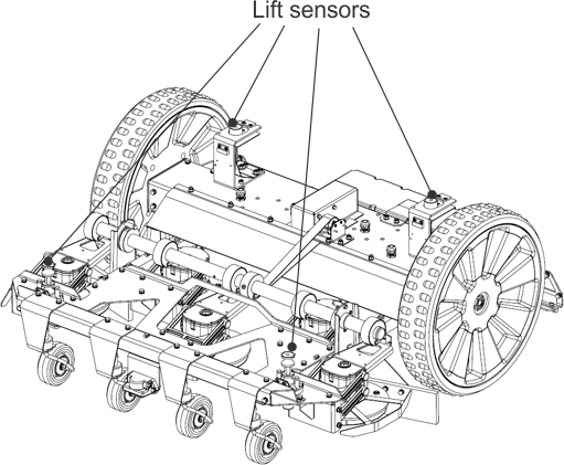
Lift and Body Displacement Sensors
Location of the lift sensor attachments
G525071
Lift sensors are attached
to the body of the robot at 4 points. If the robot touches a low object
which pushes the bodywork up or if someone
tries to lift the body, the lift sensors will react. The robot will
stop mowing and move backwards. If this
movement frees the obstacle from the body, the robot will perform
a manoeuvre to avoid the object and continue mowing. If
not, after 10 seconds the robot will register an
alarm and remain in safe mode (stationary) until the obstacle is removed.
Coil
The
induction coil detects the intensity of the magnetic field that is
generated within the peripheral wire. The maximum intensity
is located on the wire which causes the robot
to stop, rotate and then continue mowing in a new direction.
Tilt Sensor
The tilt sensor detects the angle
of the slope on which the robot is working. If this angle exceeds
30° (58%), an alarm will be raised
and the robot will stop moving.
Rollover Sensor
The rollover sensor detects whether
the robot has been tipped upside down or whether someone is trying
to start the motor when the robot is upside
down.
Temperature Sensor
The temperature sensor measures
the ambient temperature and will prevent the robot from operating
if this temperature is too low. The minimum
temperature at which the robot can operate is set as an operating
parameter.
RTK GPS Receiver
This sensor collects data from
satellites to determine the robot's precise global location.
Attachments/Accessories
A selection of Toro approved attachments and
accessories is available for use with the machine to enhance and expand
its capabilities. Contact your Authorized Service
Dealer or authorized Toro distributor or go to www.Toro.com for a list of all approved
attachments and accessories. To ensure optimum performance
and continued safety certification of the machine, use only genuine Toro replacement parts
and accessories.
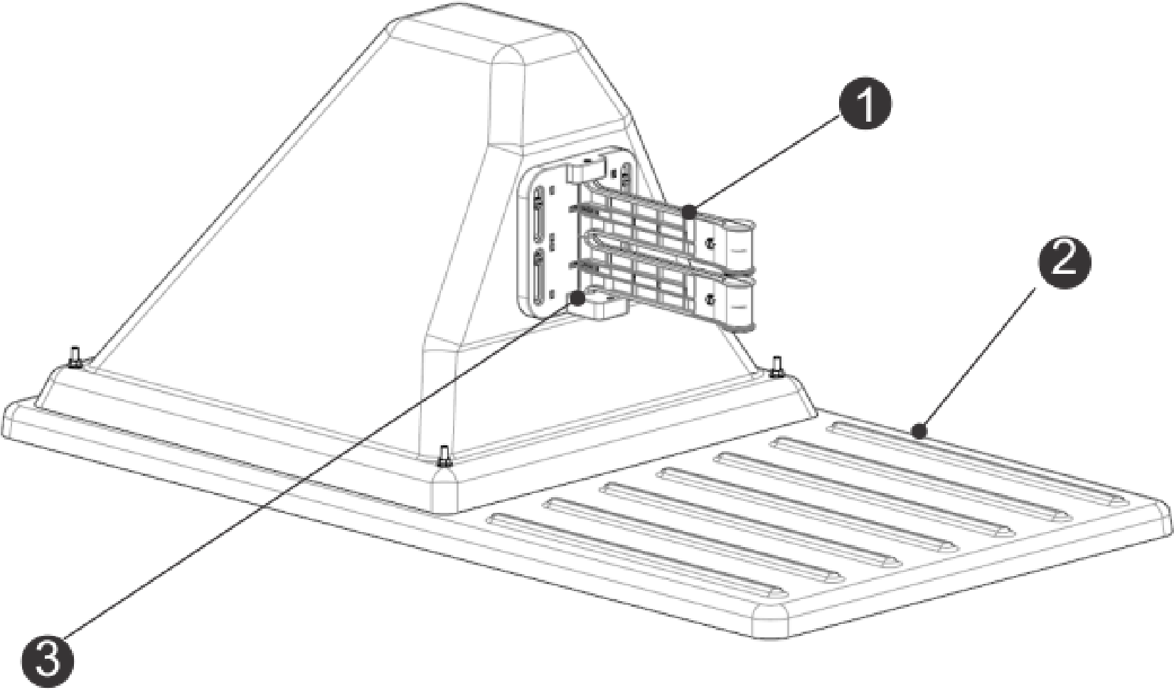
Charging Station Overview
Charging Station Components
G525910
-
Charge arms
-
Base
-
Occupation sensor
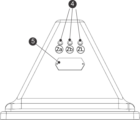
Rear view of the charging station
(2 zone light configurations shown)
G520731
-
LED indicators
-
Identification label
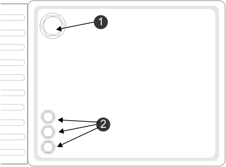
Bottom View of the Charging Station
(2 zone light configurations shown)
G520732
-
Power cable input
-
Peripheral cable input
LED Indicators
The LED indicators show the current
state of each wire. Refer to the following table.
| Green - blinking
|
The wire is operating normally. |
| Red - blinking
|
No peripheral wire can be detected.
This could be because the wire has been cut or that it is too long. |
| Red - steady
|
This indicates a problem. This
could be due to the wire being too short, less than 200 m (656 ft),
or there is a problem with
the electronics. |
The LEDs are labelled as follows:
- ZL: The wire for the loop zone
- Za: The wire for the working zone
A
- Zb: The wire for the working zone
B
Note: If you are using a charging station with multiple loops and you are
not using one of the loops, the LED will blink red. To
stop the LED from blinking red, turn the channel on
the board to 9.
Specifications
Note: Specifications and design are subject to change without notice.
Capacity
| Maximum working area [m2]
|
75,000 m2 |
| Recommended working area [m2]
|
55,000 m2 |
| Mowing width [mm] |
1033 mm
|
| Working speed [kph] |
3.6 kph
|
| Maximum slope [%] |
45% (24°)
|
Cutting
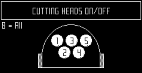
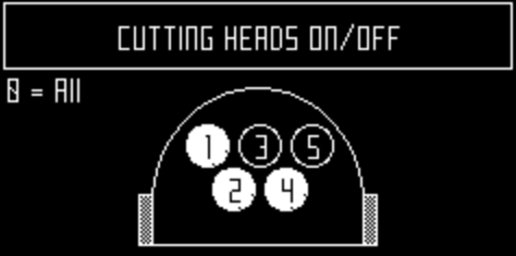
| Number of cutting heads |
5
|
| Number of cutting blades |
15
|
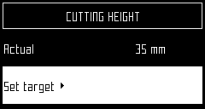
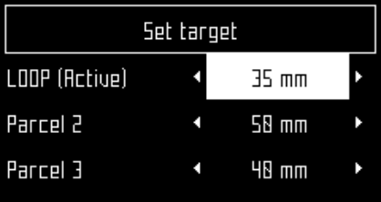
| Minimum cut height (standard disc/low
height disc) |
20 mm / 15 mm
|
| Maximum cutting height (standard
disc / low height disc) |
100 mm / 90 mm
|
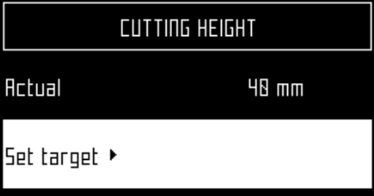
| Adjustment of cutting heads |
Electronic
|
| Maximum noise level (measured
at 5 m) |
52 db
|
Battery
| Type
|
LIFePo4
|
| Nominal voltage [V] |
25.6 V
|
| Nominal capacity [Ah] |
19.2 Ah
|
| Energy [Wh]
|
491.5 Wh
|
| Working temperature range |
-5°C an +60°C |
| Average mowing time [min] |
110
|
| Average time to full charge [min] |
90
|
Weight and Dimensions
| Weight [kg]
|
71 kg
|
| Length [mm]
|
1,110 mm
|
| Width [mm]
|
1,278 mm
|
| Height [mm]
|
515 mm
|
Software and Monitoring
| Security PIN code |
Yes
|
| GPS location
|
RTK
|
| Robot management via server and
app. |
Standard
|
Intelligence
| Sonar detection of obstacles |
Multiple
|
| Return to station via GPS |
Yes
|
| Type of mowing
|
Patterned
|
| Multiple starting zone |
Yes
|
| Multi field (optional) |
Yes
|
| Multi robots/station |
No
|
Safety
| Sonars for obstacle detection |
5
|
| Resistive bumper for collision |
1
|
| Front lift sensors |
2
|
| Rear lift sensors |
2
|
| Rear collision sensors |
2
|
| Roll over / tilt sensor |
1
|
| Cutting head deflectors |
2, 1 one each outer cutting head |
Maintenance
Maintenance Overview
- Maintenance refers to a set of
tasks that should be carried out regularly throughout the mowing season.
- The service interval depends to
some extent on the operational load of your robot, but it is recommended
that it is serviced by an authorized technician
at least once a year.
- Whilst maintaining your robot
for optimum performance, do not attempt to make any changes to your
robot. You risk disturbing its operation,
causing an accident, and damaging parts.
Note: If you notice any unusual behavior or damage - call a technician.
- When carrying out these maintenance
procedures the following safety regulations should be observed:
- Stop the machine: Always switch
off the power and wait for the all moving parts to stop before handling
the machine.
- Operate the disabling device before
the following:
- Before working on or lifting the
machine.
- Before clearing a blockage.
- Before checking, cleaning or working
on the machine.
- After striking a foreign object
to inspect the machine for damage.
- If the machine starts to vibrate
abnormally.
Keep
all nuts, bolts and screws tight to be sure the machine is in safe
working condition.
- Use gloves: Protective gloves
must be worn whenever handling the machine, and especially when handling
the cutting system.
- Always use OEM (Original Equipment
Manufacturer) parts. In addition to the risk of accidents, the use
of any non-OEM parts will result in the
annulment of the guarantee for any resulting damage.
Recommended Maintenance Schedule
Note: These procedures should be carried out at the recommended frequency
by the regular user of the robot.
Note: Throughout the mowing season you should regularly check that all
screws, nuts and bolts are properly tightened. Tighten any
that are loose, and if there is damage or evidence
of a problem contact an authorized technician.
| Before each use or daily |
|
| Every 40 hours |
|
| |
|
|
|
|
|
|
|
|
|
|
|
|
|
|
| Every 6 months |
|
|
|
| Yearly or before storage |
|
| |
Electrical System Maintenance
Checking the Wiring
-
Visually
inspect the wiring under the robot. If any problems are detected,
contact an Authorized Service Dealer.
Battery Service
The automatic (programmed) operation
of the robot optimizes battery life. It is advisable to allow the
robot to manage its working cycles. If these
work cycles seem unusually short, contact an Authorized Service Dealer
to check the condition of the battery.
Note: It is possible to monitor these cycles using the portal.
Cutting Unit Maintenance
Inspecting the Cutting Unit
-
Inspect the
blades, blade bolts, and cutting disc assembly each week to maintain
the proper cutting function.
Replacing the Blades
The condition
of the cutting blades is essential for a satisfactory mowing operation.
The service life of the blades depends on
a number of factors. Cutting disc assembly parts should be replaced
whenever they are damaged.
 |
Warning |
|
The blades are sharp; contacting
the blades could result in death or serious injury.
Use care when
replacing or cleaning the blades.
-
Rotate the
disc, so that the screw head holding the blade is visible.
-
Remove the
blade by removing the screw.
-
Install the
new blade and tighten the screw.
Note: After any intervention on the cutting heads, rotate each of them
independently and verify rotating one does not cause the
others to rotate.
Overview of Blade Replacement
The frequency
with which blades needs to be replaced depends on the robot type,
its use and the ground it is working on. Since
the condition of the blades is essential for satisfactory mowing
it is recommended that you check this part of your robot
each week after installation and at the beginning of
each new mowing season.
The pantograph allows the blade
to follow the curves of the ground. If the pantograph is not operating
correctly, blades can become blunt or break.
The pantograph should be checked and cleaned regularly.
Refer to the
following list of ways in which you can prolong the life of your cutting
blades.
- Make sure the terrain is even.
If the terrain has severe bumps or dips in it, the cutting head may
not be able to follow the contours of
the terrain and blades my hit the ground. Try to even out the terrain
and if necessary exclude very uneven patches
from the mowing area.
Note: Furrows may appear near the charging station. It is therefore recommended
to level the ground near the station or lay artificial
turf.
- Remove molehills. When the robots
hits a molehill, the blades slow down or may stop. Once past the molehill,
the blade returns to a normal speed.
The resistance of the earth and the changes in speed might loosen
the screws (or damage the screw hole).
- Avoid bare patches. The presence
of bare patches within a grassy zone will cause the rotational speed
to change. If this speed shift occurs
too often it may damage the pivot and the screw hole. To avoid this
problem you can raise the cutting height
so that the robot is cutting less grass and speed differences
are diminished. Alternatively the bare patches can be re-seeded.
- Avoid contact with nylon ground
marker. These can cause bluntness. It is recommended to lower them
below your cutting height.
- Avoid low solid obstacles in the
grass. These include sprinklers, stones, roots... Stones and other
moveable objects should be removed.
To avoid permanent solid objects such as sprinklers, set the cutting
height to be higher than the obstacle, or
adapt the mowing area to avoid them.
Note: Removable goals are another example of a solid obstacle which can
not be detected by the robot. Make sure they are removed
before the mowing is scheduled.
- Remove tall weeds near the peripheral
wire. Tough tall plants can blunt or damage the blade. It is therefore
preferable to keep clear the areas around
your peripheral cables.
Cleaning
Cleaning the Machine
During periods
of wet weather it is necessary to ensure that mud and grass do not
accumulate on the moving parts: the wheels
and the cutting heads. These should be inspected and cleaned daily.
-
Hit the red
button to stop the robot.
-
Turn the
machine onto its rear side.
-
Turn the
machine off.
-
Remove any
accumulations of grass and dirt using a blower, compressed air, and/or
a wire brush.
-
Rub the body
with a soft, damp cloth or sponge.
-
If the body
is very dirty, use a soapy solution or washing-up liquid.
Cleaning the Charge Contacts
-
Rub the charge
contact surfaces with sandpaper (280 grade) until they appear clean.
Cleaning the Bumper
-
Check that
the bumper material is intact; no cuts or tears. If it is, contact
an Authorized Service Technician.
-
Clean the
bumper with a damp cloth.
Cleaning the Sonar Sensors
The sonar sensors need to be kept
clean if they are to operate properly. All need to work properly.
If any of the sensors are not operating properly
an alarm is issued.
-
Remove any
mud, grass or dirt and wipe with a damp cloth.
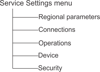
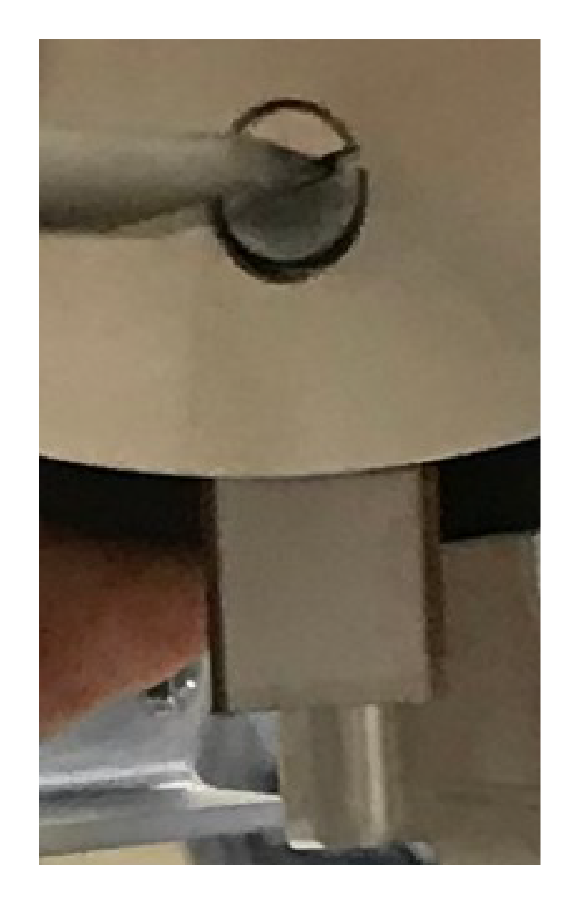
Cleaning the Front Wheels
-
Remove any
mud and grass with a wire brush or a cloth
-
Check that
the wheels rotate easily and that there is not too much play. If there
is too much play, replace the wheels using
genuine Toro Replacement parts.
Cleaning the Front Wheel Axle
-
Clean the
front wheel axle with a brush and/or a cloth.
-
Visually
inspect the axle. If there is a problem, replace the axle using genuine
Toro Replacement parts.
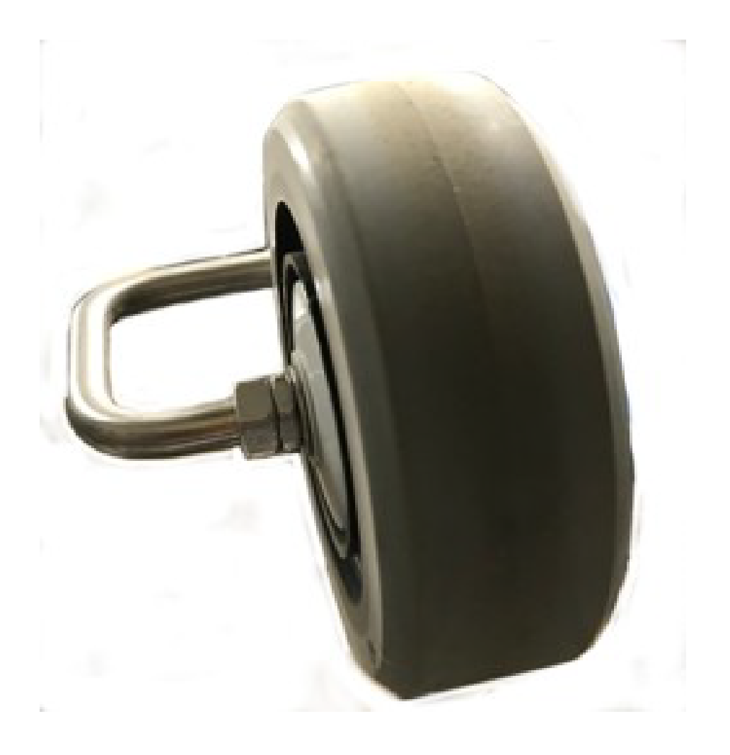
Cleaning the Cutting Head
-
Clean the
cutting head using a brush. If compressed air is available, this is
preferable.
-
Check that
the entire cutting head moves smoothly backward and forwards as shown
by the arrow in the figure below.
Cleaning the Cutting Disk
This procedure should be performed
weekly. This is important if the cutting height is set to 25 mm (2.2
cm) or less. If this is the case, the wear
on the anti-friction disc is increased and will need to be replaced
at least every 2 months
-
Clean the
cutting disc using a brush. If compressed air is available, this is
preferable.
-
Check that
the cutting disc rotates smoothly. If there is a problem, replace
the cutting discs using genuine Toro Replacement
parts.
Cleaning the Rear Wheels
-
Remove any
mud and grass using a wire brush.
Glossary
Border mode
When the robot cuts the
grass at the very edge of the field. This is done a number of times
per week.
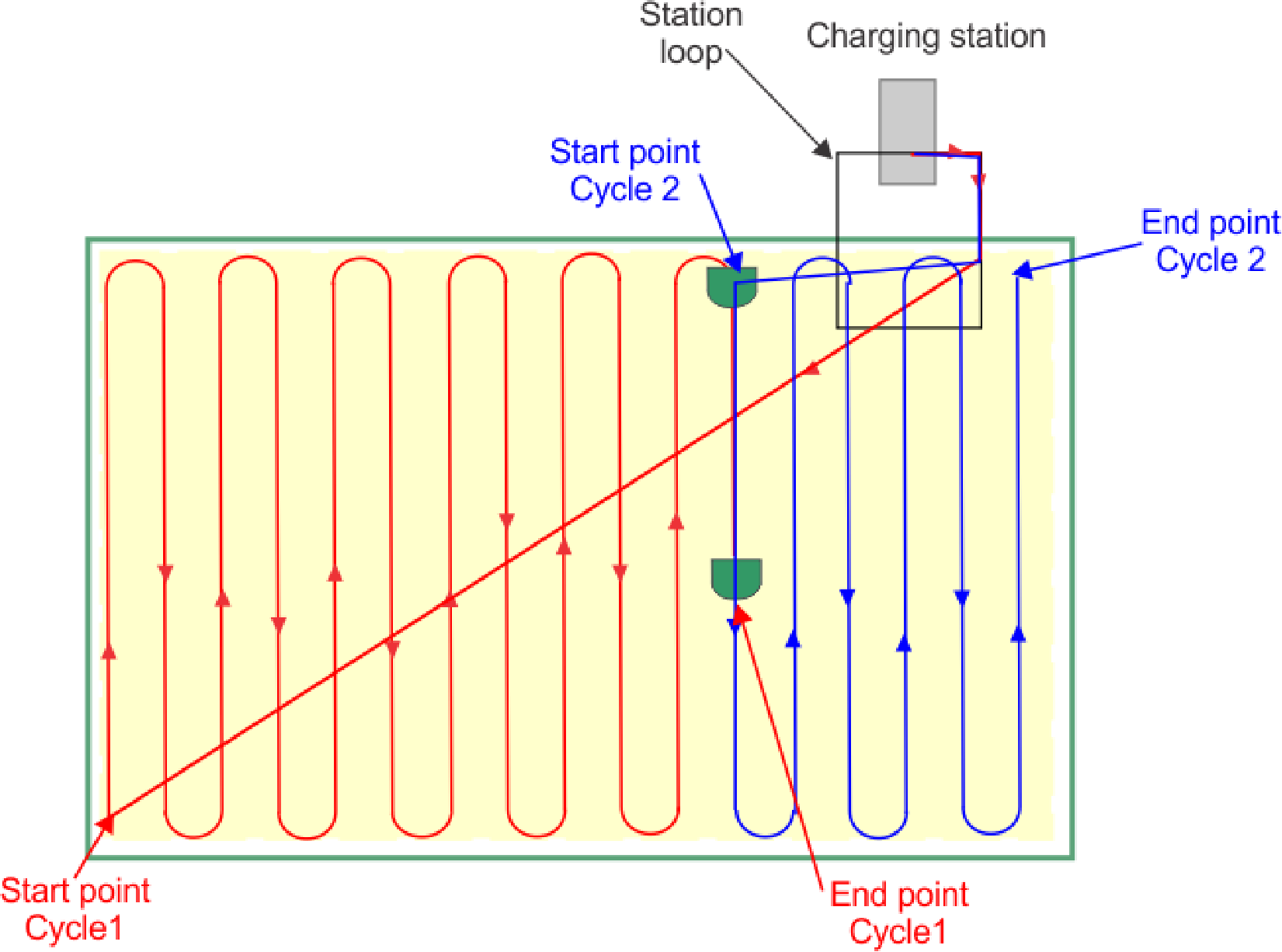
Cycle
A cycle is a working session
of the robot. It starts when the robot leaves the station and ends
when it returns to the station or there is an problem
that halts the working cycle.
Entity
A collection of robots
and users that operate within a site. Information about the robots
in an entity can be viewed on the web portal.
GPS navigation zone
This is an
RTK GPS zone that is defined by the border discovery process. it encompasses
the entire working area. Sub-zones can then be created
by copying and editing this zone to optimise the efficiency of the
robot.
GPS point
A specific point within
a parcel that the robot uses to return to or leave a station. The
point is defined by its latitude and longitude.
The robot takes a direct route to this point then follows the trackborder
and the loop wire to return to the station.
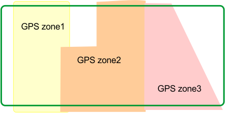
GPS zone
A GPS zone is defined by
set of GPS coordinates. It allows a wired parcel to be subdivided
without having to use additional wires and channels.
GPS zones in a wired parcel
G520046
This provides greater flexibility
in defining working areas since the robot can be scheduled to work
with optimum efficiency over the zones.
Idle
A robot will enter idle mode,
if the current mission has been ended using the Stop button. By default
the robot will enter the sleep mode after 15 minutes.
Island
A loop in the peripheral
wire specially installed to prevent the robot working inside it. The
peripheral wire is taken around the obstacle and
the approach and return wires laid next to each other.
Map
Map of the robots routes on the
portal.
Mapping
The information built up
by the robot using GPS data.
NoGo zone
GPS defined No-Go zones
are regions on the field defined by GPS coordinates where the robot
can never enter during any of its autonomous operating
states. GPS defined No- Go zones are used to exclude zones from the
working area of the robot that cannot be detected
during border discovery. Use of GPS defined No-Go zones allows the
robot to calculate the most efficient mowing pattern
in advance. GPS defined No-Go zones are used to exclude obstacles,
typically done by islands and pseudo islands.
Obstacle
An object in the field
that the robot must avoid. Obstacles can be permanent (e.g. trees,
furniture) or transitory, (e.g.. animals). Obstacles
are detected by sensors. Permanent obstacles can be avoided by making
loops in the peripheral wire to form "islands" or
"pseudo-islands".
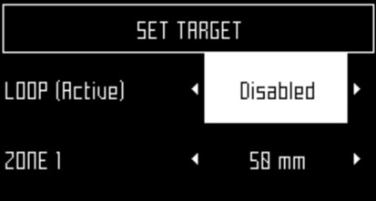
Parcel
An area to be mowed within
a peripheral wire. At least one parcel is associated with one wire.
Several parcels can be defined.
Percentage
This represents the proportion
of time that the robot will spend working a particular parcel. If
there is only one parcel, the robot will spend 100%
of its time there.
Peripheral wire
A wire laid
below the surface of the field which defines the area in which the
robot works. The area defined by the peripheral
wire is termed a "parcel".
Pseudo-island
The peripheral
wire is taken around the obstacle, maintaining a specific distance
between the approach and the return wires.
Robot status values
- Off
Robot has been switched off.
- Off after alarm
Robot has switched itself off
after an alarm.
- Alarm
Robot is in a state of alarm.
- Staying
Robot is waiting at a charge station.
- Charge
Robot is charging the battery.
- Heading for unload station
Robot is going to the drop pit
station to unload balls. This status starts when a robot decides to
return to the station.
- Heading for charge station
Robot is going to the charging
station. This status starts when the robot decides to return to the
station.
- Leaving station
Robot is leaving the station and
starting to work.
RTK GPS zone
The working area for a
robot performing pattern mowing. The RTK GPS zone is defined by the
robot making a tour of the peripheral wire.
Site
The entire area which includes
the area in which the robot works.
Sleep
A robot will enter sleep
mode 15 minutes after an alarm has occurred which has not been cleared.
After 2 days in sleep mode, the robot will enter
the OFF mode. This will also occur if the battery charge level reaches
a low level. When in sleep mode the robot uses minimal
power to reduce the risk of the battery.
The robot can be brought out of
sleep mode by:
- clearing the alarm and switching
the robot on, using the button on the LED screen
- pushing the robot to the charging
station, if the battery is flat
- sending a remote wakeup command
via the web portal
Station loop
A station loop is a short
wire around a charging station which is used to guide the robot into
the station. When the robot detects that it is in
the station loop it follows the wire until it arrives in the station.
Terrain
An area of grass surrounding
the field that is not to be mowed.
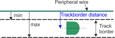
Track border
A width of grass around
the edge of the parcel in which the robot works. The robot follows
the track border when leaving or returning to a
station unless it is using GPS. There is no track border specified
for a wire that acts as a "return to station loop".
The track border lies next to
the peripheral wire, and is defined by minimum and maximum dimensions
set as installation parameters. It is wider than
the robot. The path taken by the robot within the track border is
selected in a random manner. This ensures that the
robot does not repeatedly move along the same path and so create ruts
in the field. If the robot encounters an obstacle
whilst in the track border, the sensors will cause it to reverse
and then rotate through a random angle in order to proceed.
This may be repeated a number of times if necessary.
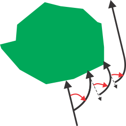
Maneuvers to avoid an obstacle
within the track border
G520315
Trackwire
Movement of the robot along
the loop wire as it enters and leaves the station.