Introduction
 |
Warning |
|
Failing to follow the operating
instructions or to receive training from an authorized Toro distributor
may result in death or serious injury.
- To maximize the safety, performance,
and proper operating of this machine, carefully read and fully understand
the content of this Operator's Manual.
- For more information on safe operating
practices, including safety tips and training materials, go to www.Toro.com.
This manual
covers the installation and maintenance of the charging station for
the Turf Pro series robotic mowers and Range Pro
series ball pickers.
Note: Information about the peripheral wires and loop wires is located
in the Operator’s Manual for each mower.
This
charging station is intended to be used by professional, hired operators
for autonomous, programmable lawn care. It is designed
for charging the batteries on the Turf Pro and Range Pro autonomous
robots. Using the autonomous robots, battery, charging
station, and base station for purposes other than their intended use
could endanger you and bystanders.
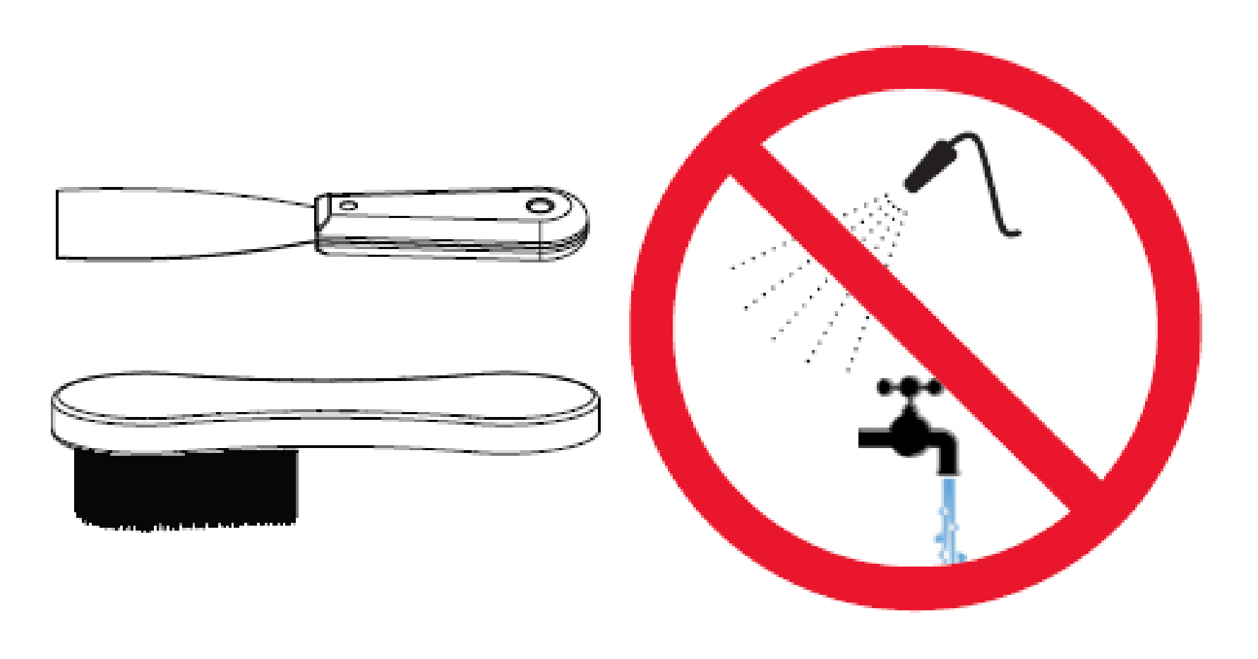
Read this information carefully
to learn how to operate and maintain your product properly and to
avoid injury and product damage. You are responsible
for operating the product properly and safely.
Getting Help
Visit www.Toro.com for product
safety and operation training materials, accessory information, help
finding a dealer, or to register your product.
Whenever you
need service, genuine Toro parts, or additional information,
contact an Authorized Service Dealer or Toro Customer Service and have the
model and serial numbers of your product ready. These numbers are
located on the serial plate on your product.
Write the numbers in the space provided.
With your mobile device, you can
scan the QR code on the serial number decal (if equipped) to access
warranty, parts, and other product information.
| Model Number: |
|
Serial Number: |
|
Manual Conventions
This manual identifies potential
hazards and has safety messages identified by the safety-alert symbol,
which signals a hazard that may cause serious
injury or death if you do not follow the recommended precautions.
This manual uses 2 words to highlight
information. Important calls attention
to special mechanical information and Note emphasizes
general information worthy of special attention.
Safety Alert Classifications
The safety-alert
symbol shown in this manual and on the machine identifies important
safety messages that you must follow to prevent
accidents.
Safety-alert symbol appears above
information that alerts you to unsafe actions or situations and is
followed by the word DANGER, WARNING,
or CAUTION.
|
Danger |
|
Danger indicates an imminently
hazardous situation which, if not avoided, will result in death or serious injury.
|
Warning |
|
Warning indicates a potentially
hazardous situation which, if not avoided, could result in death or serious injury.
|
Caution |
|
Caution indicates a potentially
hazardous situation which, if not avoided, may result in minor or moderate injury.
Product Overview
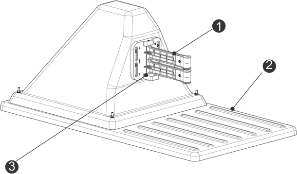
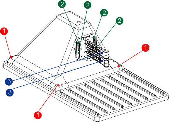
Charging Station Components
Note: Model 30914 is shown
G520730
- Charge
arms
- Base
- Occupation
sensor
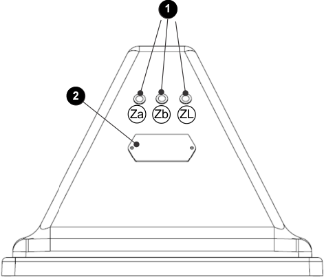
Rear View of the Charging Station
Note: Model 30914 is shown
G526516
- LED indicators
- Identification
label
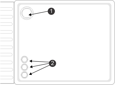
Bottom View of the Charging Station
G520732
- Power-cable
input
- Peripheral-cable
input
Occupation Sensor
The occupation
sensor is an optional feature indicating that the charging station
is occupied in charging a robot. This particularily
important when using multiple ball-collecting robots.
LED Indicators
The LED indicators
show the current state of each wire. Refer to the following table.
| Green - blinking
|
The wire is operating normally. |
| Red - blinking
|
No peripheral wire can be detected.
The wire may have been cut or is too long.
|
| Red - steady
|
This indicates a problem. The
wire may be too short (less than 200 m or 656 ft) or a problem with
the electronics. |
The LEDs are labelled as follows:
- ZL: The wire for the station loop
zone
- Za: The wire for the working zone
A
- Zb: The wire for the working zone
B
Note: If you are using a charging station with multiple loops and you are
not using one of the loops, the LED will blink red. To
stop the LED from blinking red, turn the channel on the
board to 9.
Stations
One station
is required for each robot to charge.
The maximum number of boards in
a station (and therefore wires that can be connected) is 3. If more
wires need to be connected (if 2 loops and 2
peripheral wires are required), install an extra channel board.
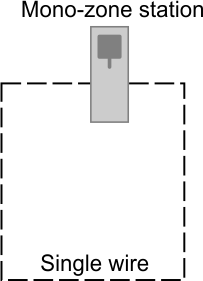
Mono-Zone Station (Loop Wire Only)
A single board is installed in
this type of station, supporting just a single wire. This type of
station would typically be used in a golf
installation, where the single wire would be the loop wire. This board
and wire is labelled ZL on the station.
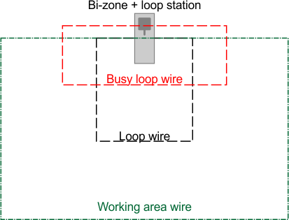
Bi-Zone and Loop Station
For golf course installation:
These 3 wires could be used for:
- A loop wire to allow the robot
to return to this station.
- A peripheral wire defining the
area in which the robot will work.
- A busy loop used when 2 ball-collecting
robots are in operation.
For mower installation:
3 boards will be installed in
this type of station. These boards and wires are labelled ZL (for
the loop) and Za and Zb (for the working zones).
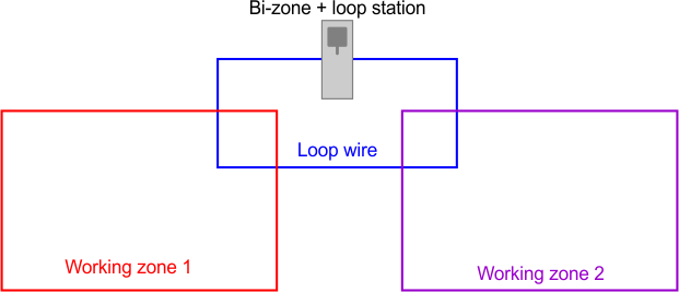
This
station can be used for:
- A loop wire to allow the robot
to return to this station.
- 2 peripheral wires for separate
working areas.
Electronic Board
The charging station contains
a board for each wire (channel) required. A maximum of 3 boards can
be installed.
Note: If necessary, install a signal channel board in an external box.
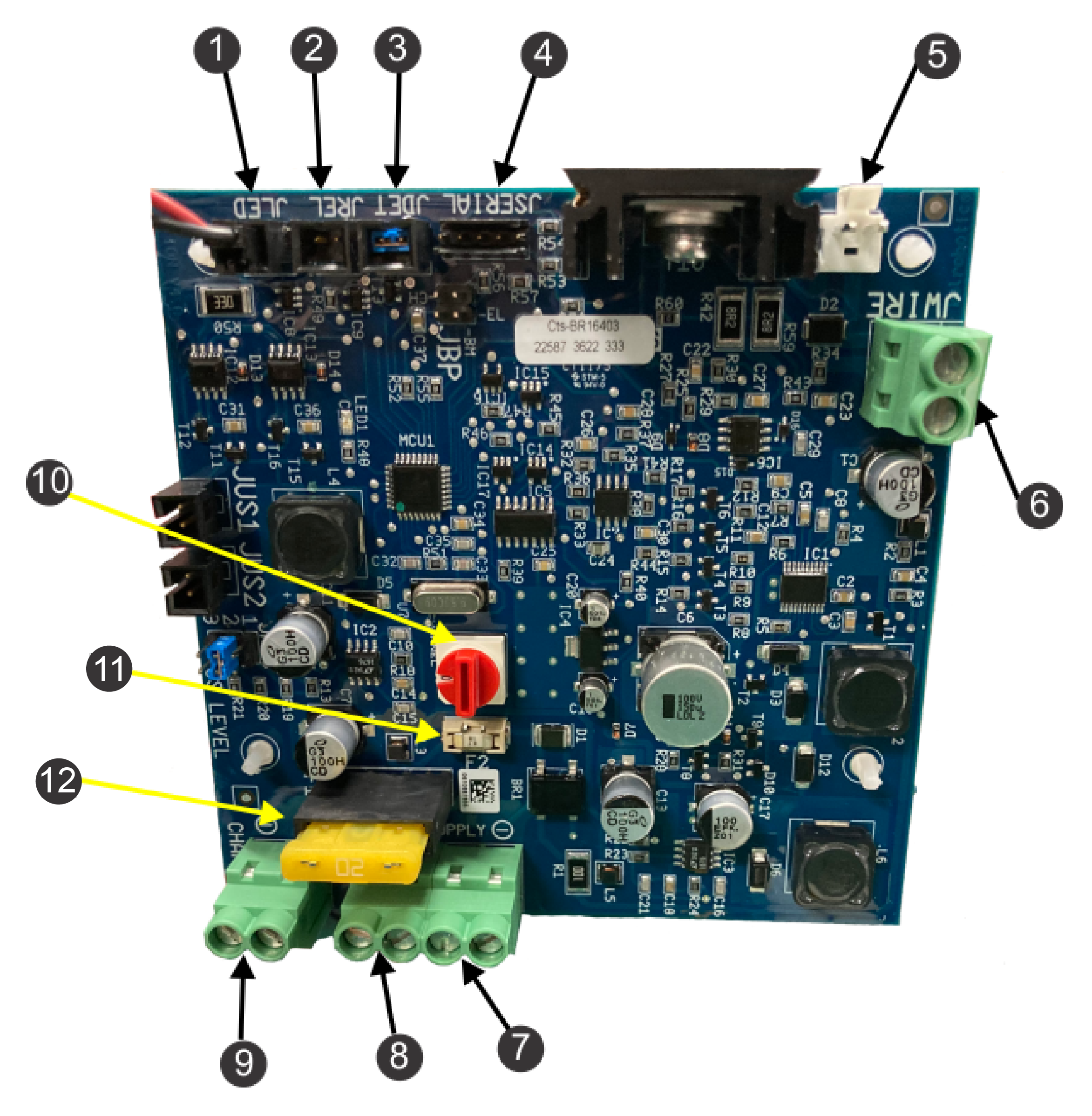
Electronic Board Components
G520838
-
Pilot LED (JLED)
-
Optional relay connection (JREL)
-
Optional presence detection (JDET)
-
PC interface for updates (JSERIAL)
-
JWire connection for surge protection
-
Peripheral wire (JWIRE)
-
Negative DC supply (JTR1)
-
Positive DC supply (JTR2)
-
32 V contact arm (JCHRG)
-
Magnetic signal channel selection
switch
-
20 A fuse (main)
-
1 A fuse (electronic board)
Specifications
Note: Specifications and design are subject to change without notice.
| Width
|
45 cm (17.7 inches) |
| Length
|
85 cm (33.5 inches) |
| Height
|
34.5 cm (13.6 inches) |
| Operating temperature |
0°C to 50°C (32°F
to 122°F) temperature protections has been implemented for higher
temperatures |
| Ingress protection |
IP54
|
| Power input
|
100-240 VAC 3.5 A 50-60 HZ |
| Charge output
|
23-32 VDC 10.7 A
|
| Output circuits
|
Class II
|
Installation
Charging Station Installation
Requirements
This is a basic installation procedure.
Each installation varies by application. Contact an Authorized Service
Dealer if you have specific questions.
One
station is required for each robot.
The installation is required to
be performed by a qualified professional.
Follow all of the national
and regional codes.
Do no bend, warp or crack the
base during the installation process.
- Develop an installation plan and
a map of the site. If the installation is for ball picker, make sure
to determine the area needed for the ball
drop.
- Identify a location for installing
the AC power supply, station loop peripheral wire(s), and field zone
peripheral wire(s).
- There should be no risk of flooding
after heavy rain.
- Obstacles must be more than 6
m (19.7 ft) away from the charging station. For more details concerning
water obstacles, refer the following section
that details positioning the station near water.
- When GPS navigation is being used,
the station should be positioned in the following ways to optimize
the GPS precision:
- to the south of the site, if the
site is in the northern hemisphere
- to the north of the site, if the
site is in the southern hemisphere
- The charging station must lie
within the range of the 4G RTK base or Wi-Fi repeater and receive
a good signal level. A signal level of
1.2 is required for the robot to be able to leave the station and
signal level of 2.0 is required for 4G RTK.
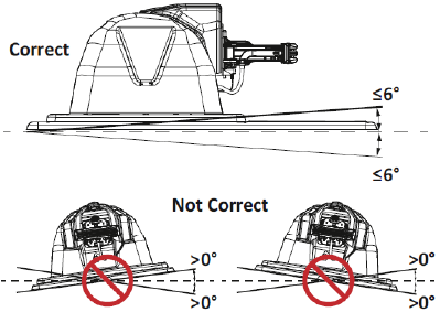
- Install the charging station on
flat ground where flooding or water accumulation will not occur.
Note: If the entire field is on a slope, install the charging station on
a flat portion at the top. The robot has no brake when
it is in charge mode and can slide away from the
charging arm contacts if the longitudinal slope is greater than 0°.
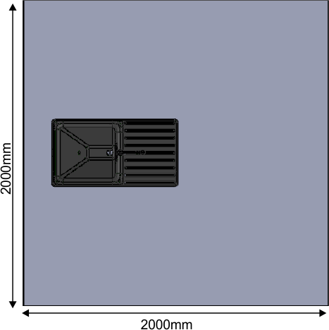
Positioning the Charging Station
Near Water
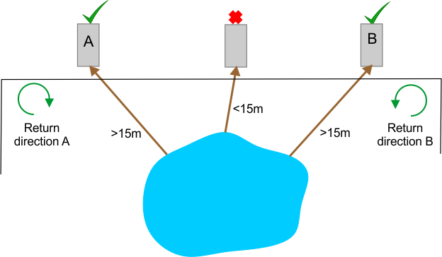
The charging station must be located
at least 15 m (49 ft) from the water's edge.
The figure below summarizes
critical factors associated with the placement of the charging station
near a water feature.
In the situation illustrated above,
two possible locations for a charging station have been shown. The
robot should return to the station from the
direction away from the water. So if the charging station is located
in point A, the robot must return to it in
a clockwise direction. If the charging station is located in point
B, the robot must return to it from a counter-clockwise
direction.
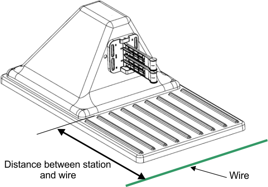
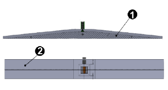
Charging Station and Wire Distance
Turf Pro 300 only: The distance between the
station and the loop wire is 0.57 m (22.4 inches).
Turf Pro 500 and Range
Pro series only: The distance between the station and the loop wire is 0.67 m (26.4
inches).
Connecting the Peripheral and
Loop Wires
-
The installation must be performed
by a qualified professional.
Follow all national and regional
codes.
If necessary, remove the lid by
removing the nuts.
-
Feed the
wire(s) through the base of the station.
Note: Model 30914 is shown.
G520732
- Power
cable input
- Peripheral
cable input
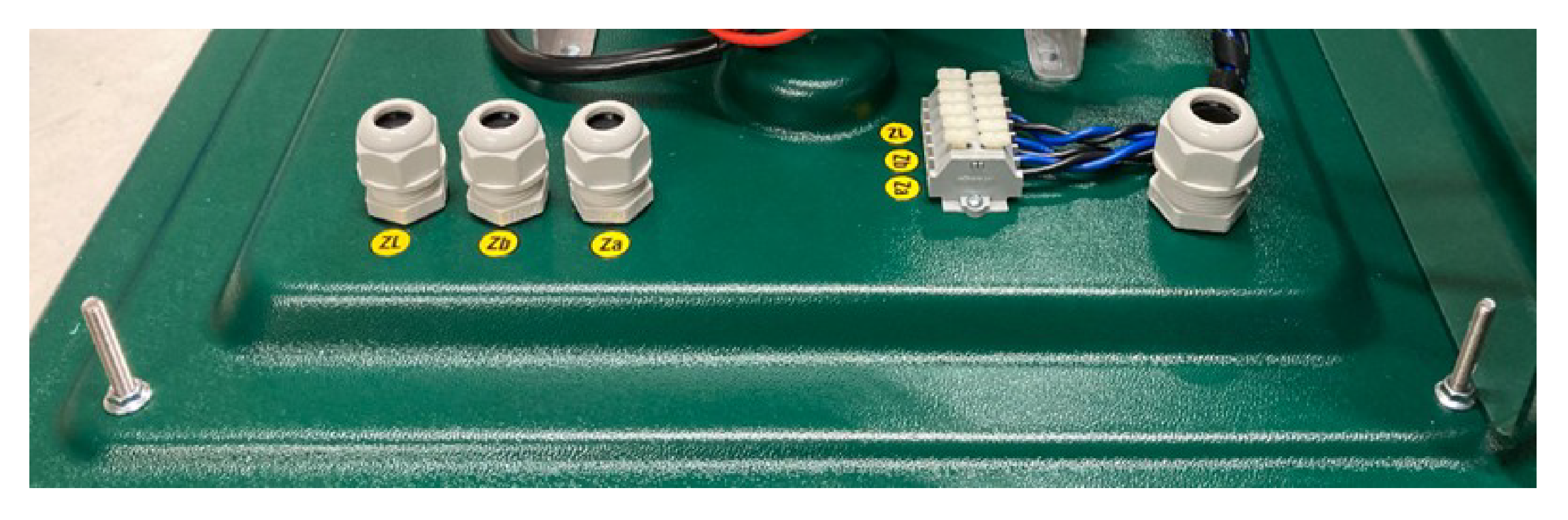
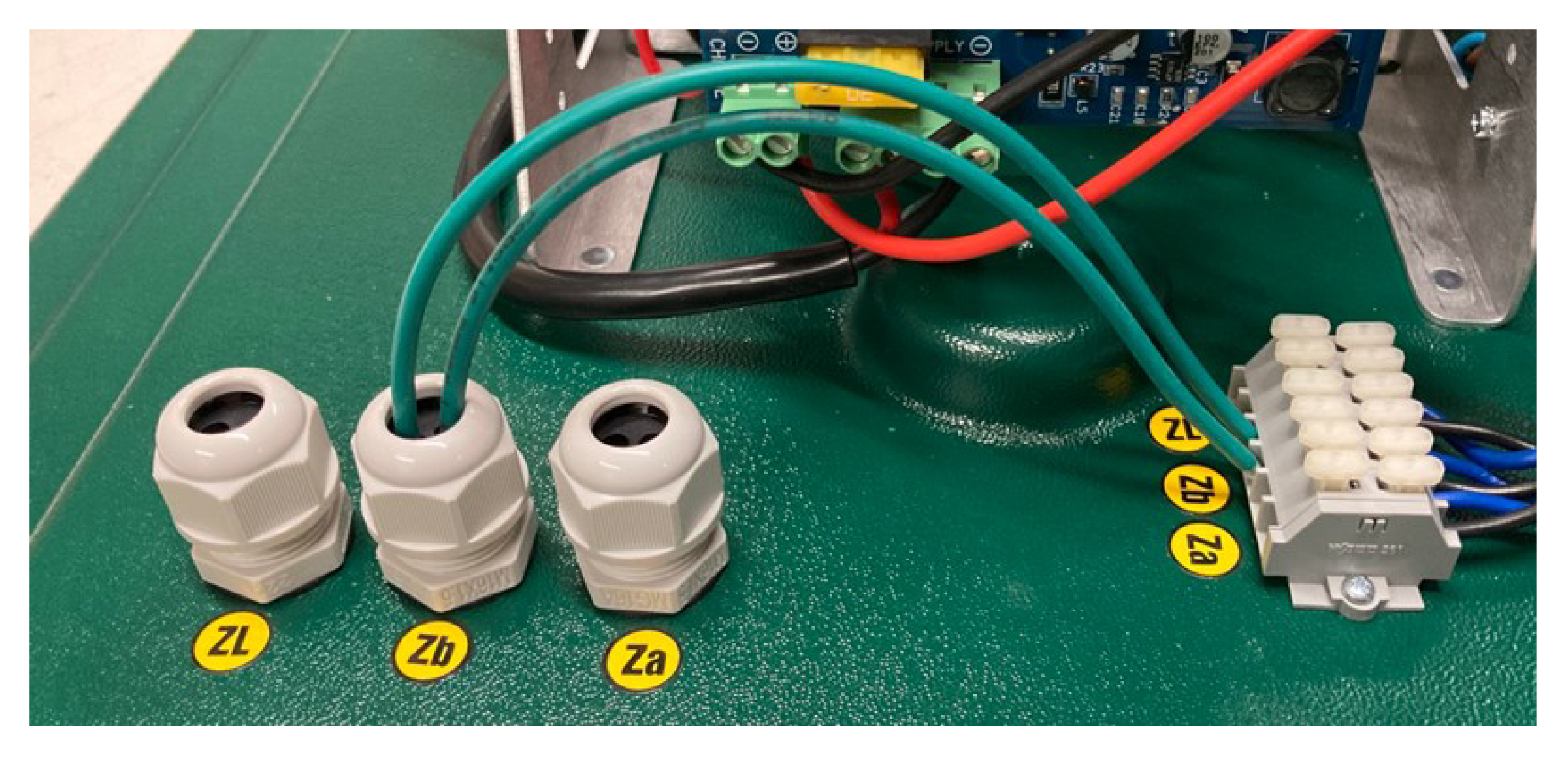
The label for
the circuit can be seen on the inside of the station base.
Note: Za and Zb are for the peripheral wires around the working areas.
ZL is for the loop wire.
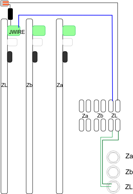
-
Connect the
2 wires to the corresponding connections on the station as shown.
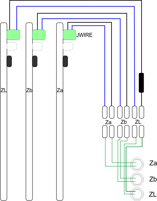
A schematic
wiring diagram for the peripheral and loop wires is shown in the figure.
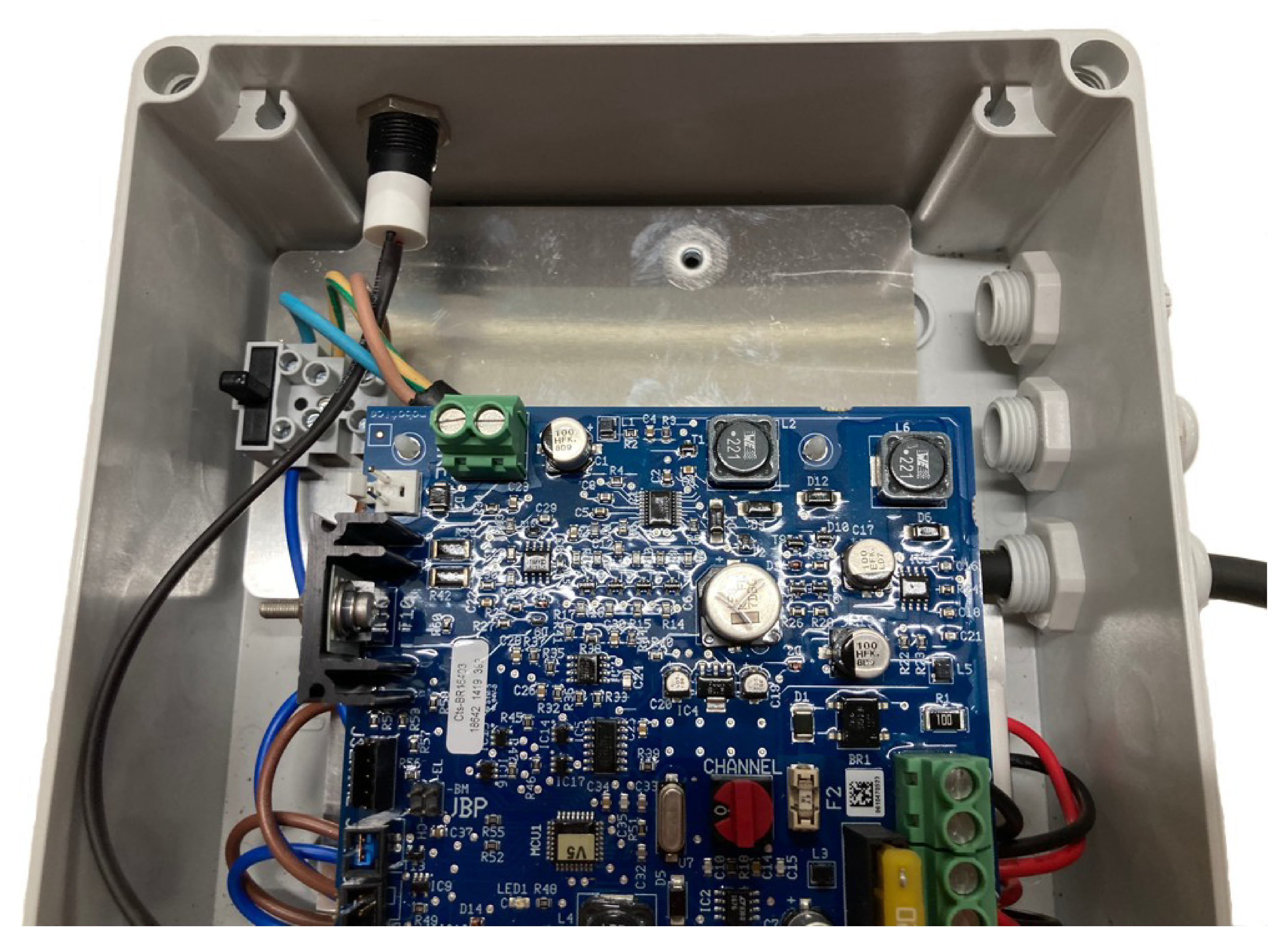
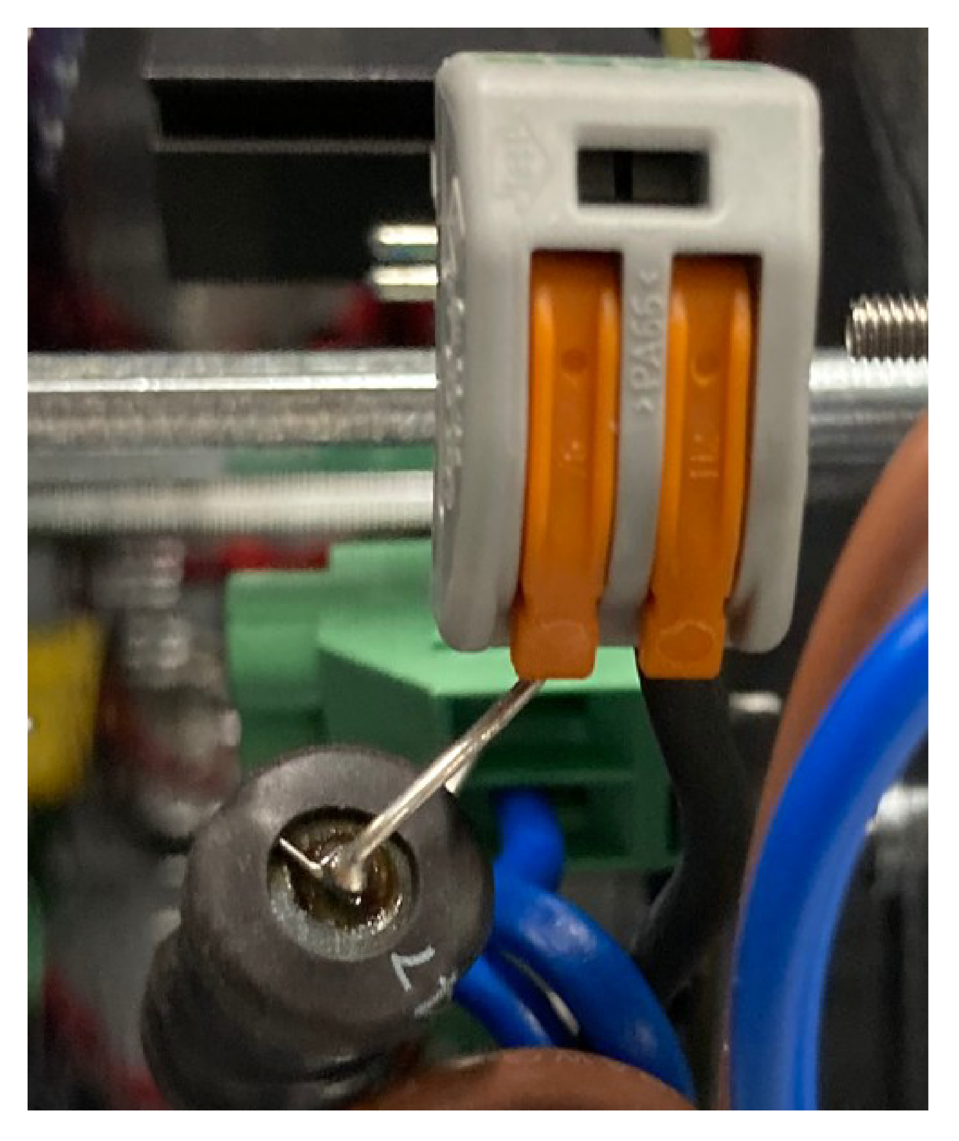
Connecting the Power Supply
-
The installation must be performed
by a qualified professional.
Follow all national and regional
codes.
Note: The charging station may only be connected to a supply circuit protected
by a Residual Current Device (RCD) with a tripping
current of less than 30 mA.
Open the station by removing the
nuts on the lid.
-
Thread the
power cable through the base .
.
Note: Model 30914 is shown below.
G520732
- Power
cable input
- Peripheral
cable input
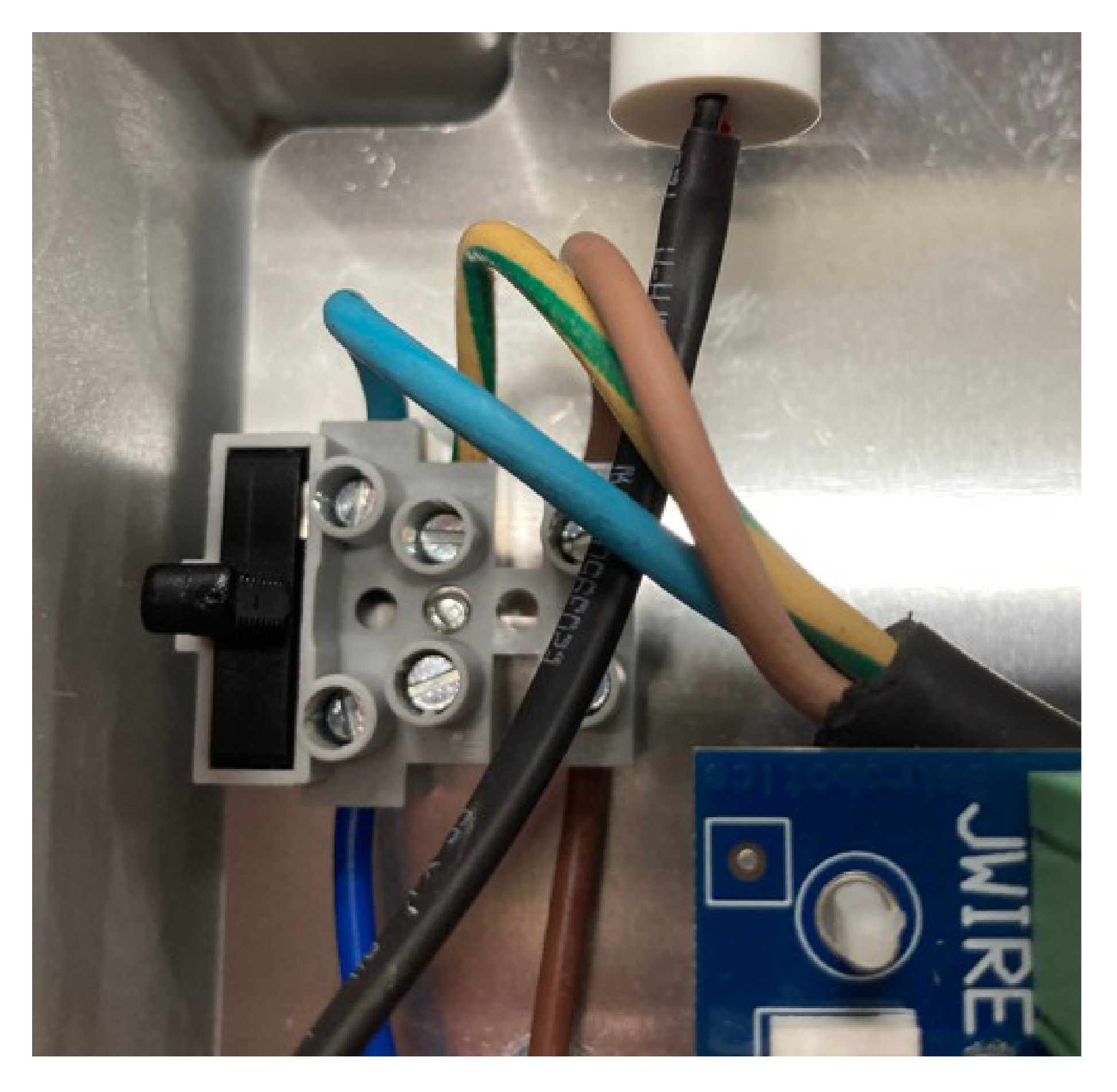
-
Note: The station needs a good ground connection.
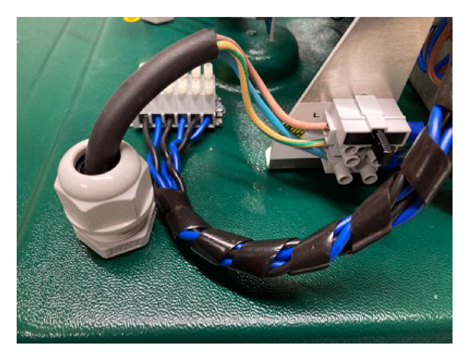
Connect the 3 wires to the corresponding
connection in the station as shown in the following figure.
- Live: upper connection (brown)
- Ground: middle connection (green/yellow)
- Neutral: lower connection (blue)
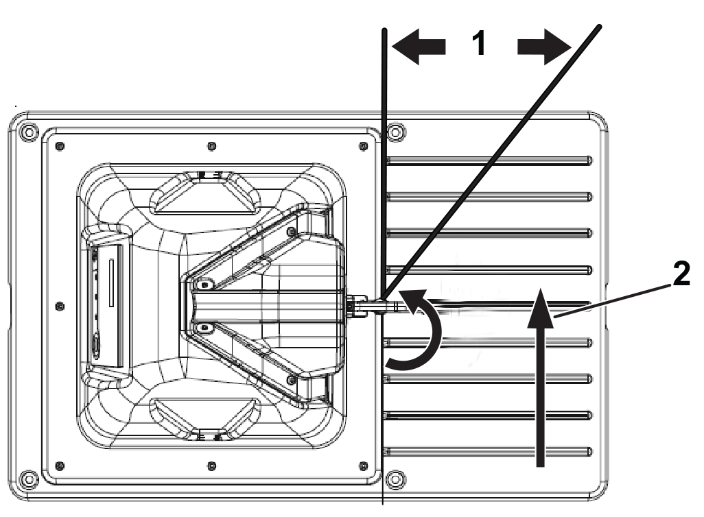
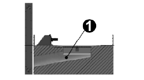
Station and Robot Alignment
The position of the charging
station must ensure that when the robot is in place:
- The height of the arms has been
set to make good contact between the charging station and the contacts
on the robot.
- The angle of the charge arms is
at 30° to 45°. The robot can charge in either direction.
G541732
-
30° to 45°
-
Robot direction
Multiple Station Installation
When considering the position
of multiple stations, the criteria listed below should be taken into
account.
In the case of a multi-station
installation, it is recommended to place the stations as a group in
a location with easy access to a power supply.
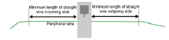
The
station should be positioned on a straight section of the peripheral
wire with defined minimum free distances on both
the incoming and outgoing sides.
- The minimum length of wire on
the incoming side is 3.5 m (11.5 ft).
- The minimum length of wire on
the outgoing side is 3.5 m (11.5 ft).
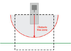
An obstacle
free zone of at least 6 m (20 ft) is required.
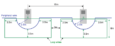
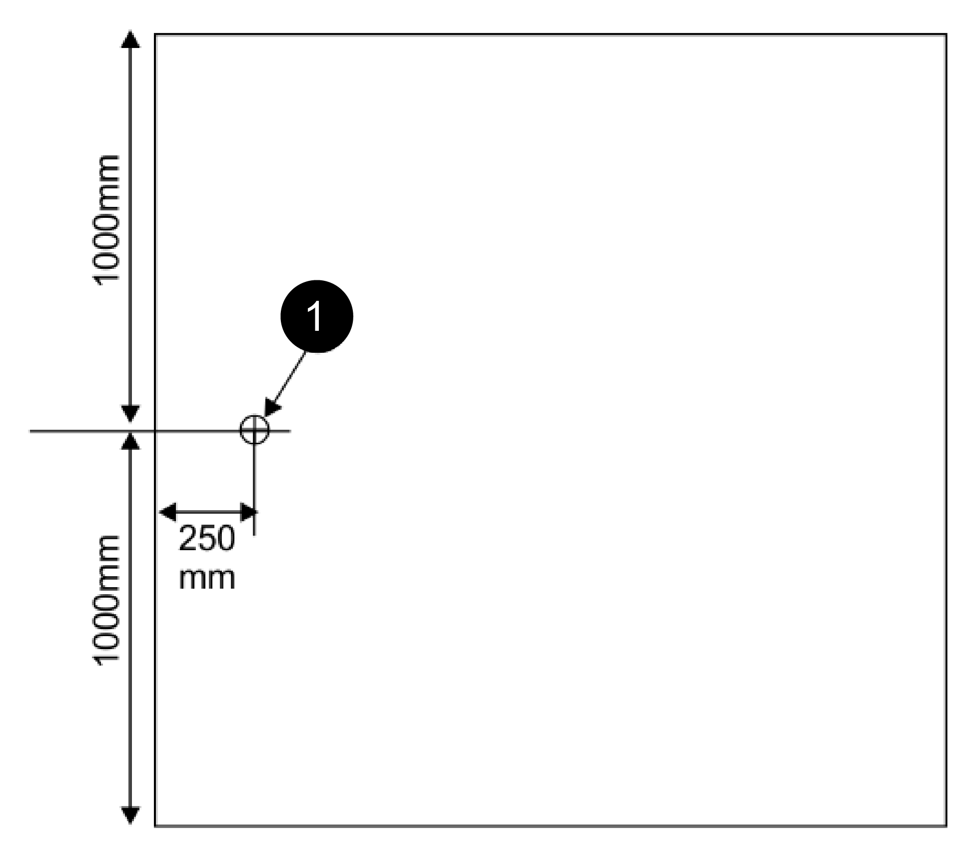
Multiple Stations Position
The dimensions
associated with the positioning of multiple stations are shown below.
The
minimum distance between stations is 15 m (49 ft).
In the example
shown below, the peripheral wire bends around the station with a 2.5
m (8 ft) radius. This is to ensure that a
working robot does not collide with a robot that is parked at the
station.
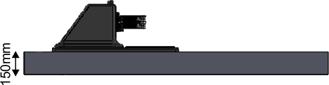
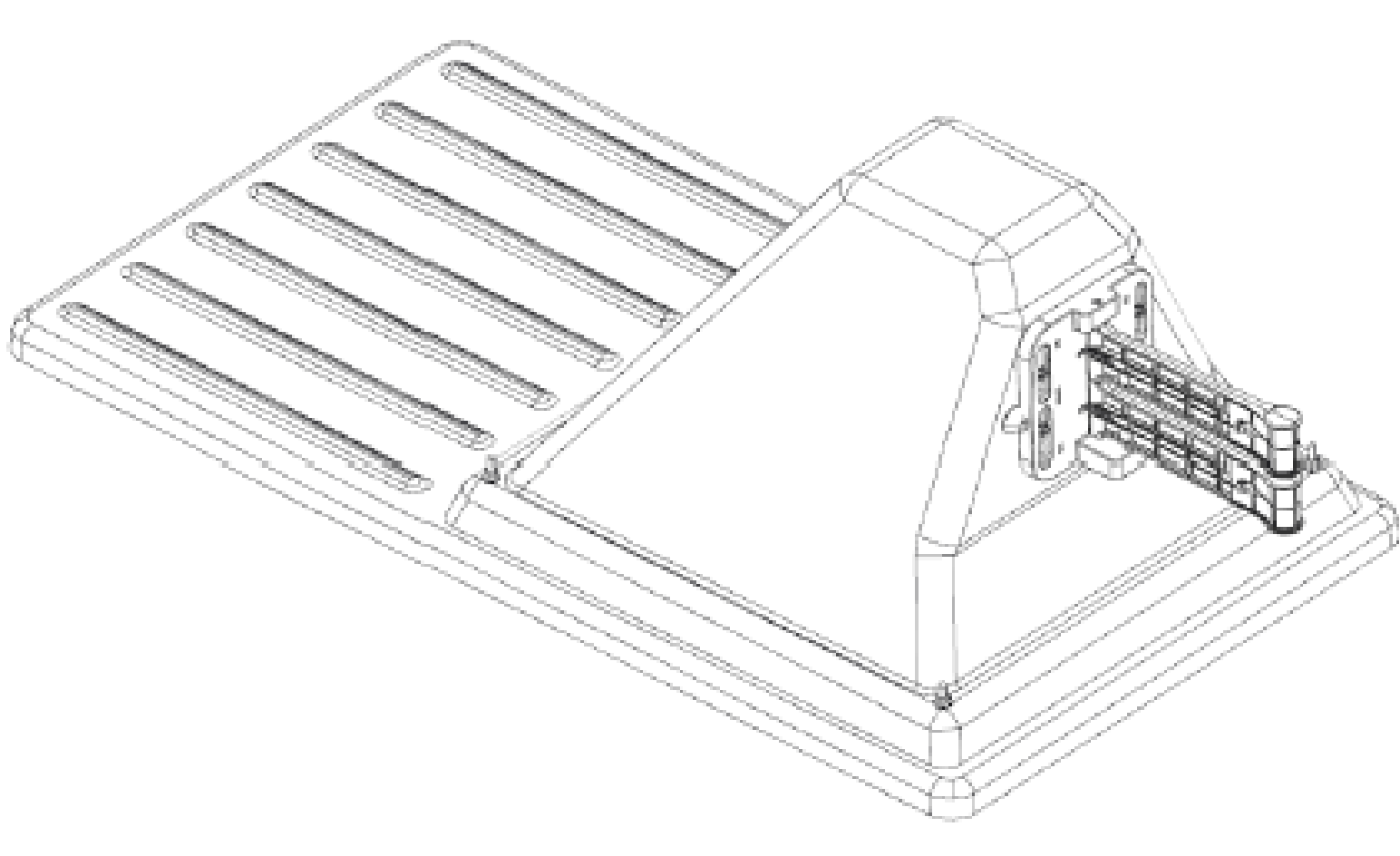
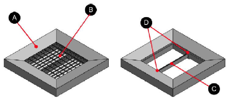
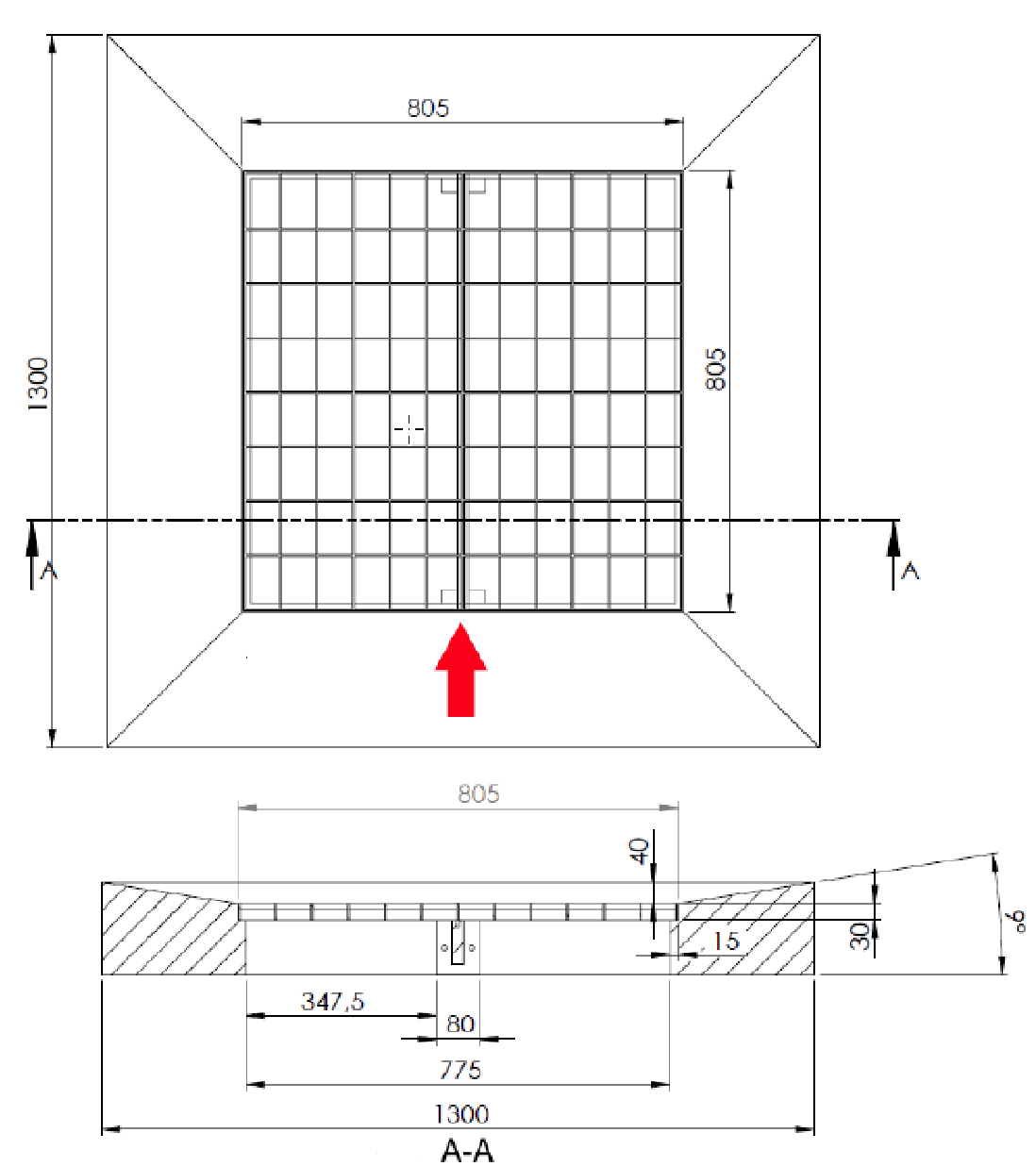
Mounting the Charging Station
on Concrete
You can mount the charging station
on a concrete base.
Note: The concrete should contain no reinforcing mesh or any other metallic
parts.
The following figures show the
recommended dimensions for this base.
G520986
-
Location of the power supply for
the base
Installing the Channel Board Outside
of the Charging Station
If multiple wires for working
areas and loops are required, or if a wire is located at a significant
distance from the charging station, it may be
necessary to install a channel board closer to the wire rather than
in the charging station. This can save on the
total length of wire required.
It may also be necessary to install
an external channel board, near the charging station, if there is
not sufficient space in the charging station.
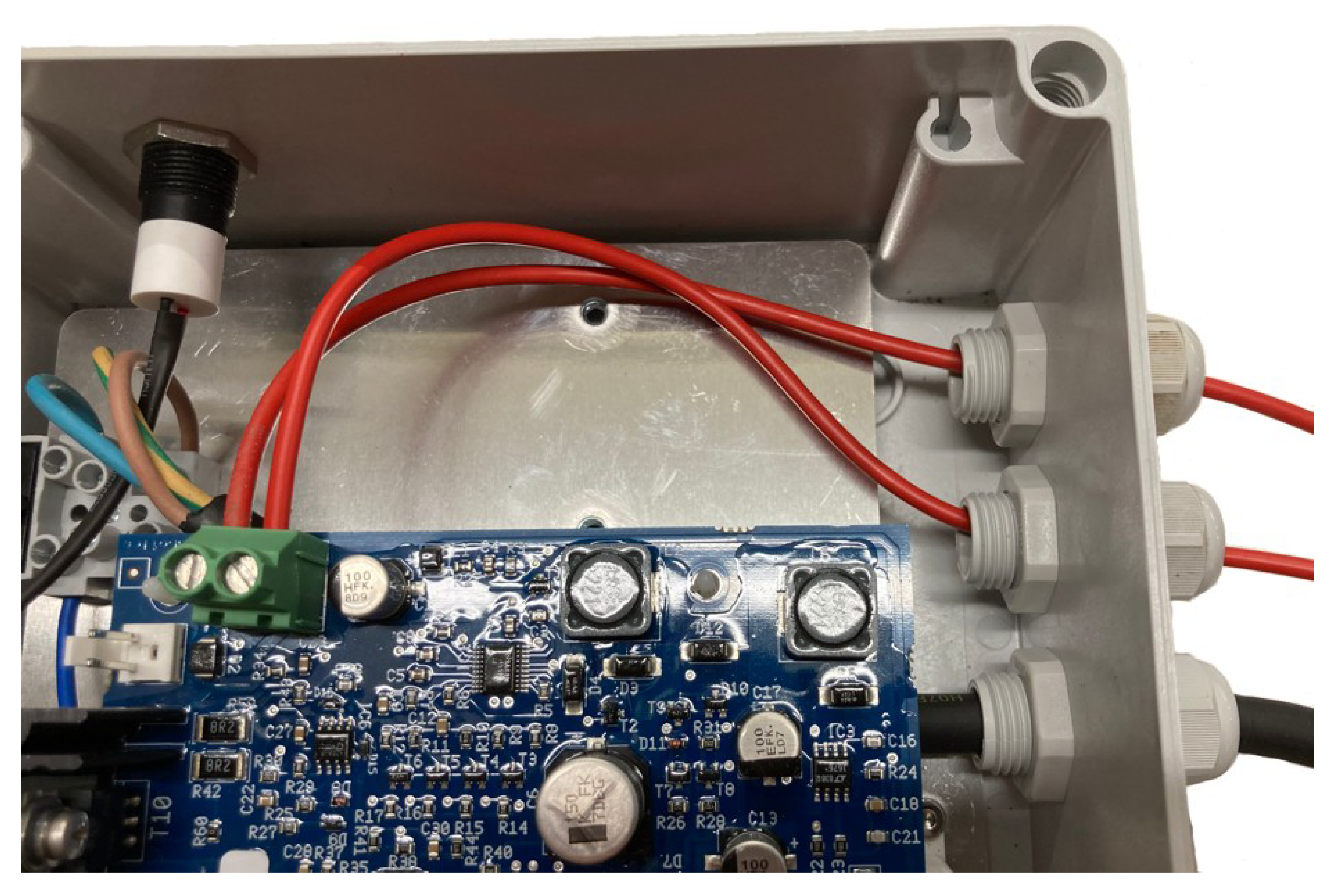
-
Insert the
mains power cable through the gland as shown in the following figure.
-
Connect the
live (brown), ground (green/yellow), and neutral (blue) cables to
the connectors in the box, as shown in the following
figure.
-
Insert the
2 peripheral wire cables through the glands as shown in the following
figure.
-
Connect the
peripheral wire cables to the connectors on the card as shown in the
previous figure.
Installing an Inductor in the
Charging Station
If the total length of any of
the wires is less than 200 m (656 ft), it is necessary to install
an inductor in the charging station. This is
important when using a small loop to return the robot to the charging
station.
Note: The loop wire circuit is labelled ZL and has the inductor installed.
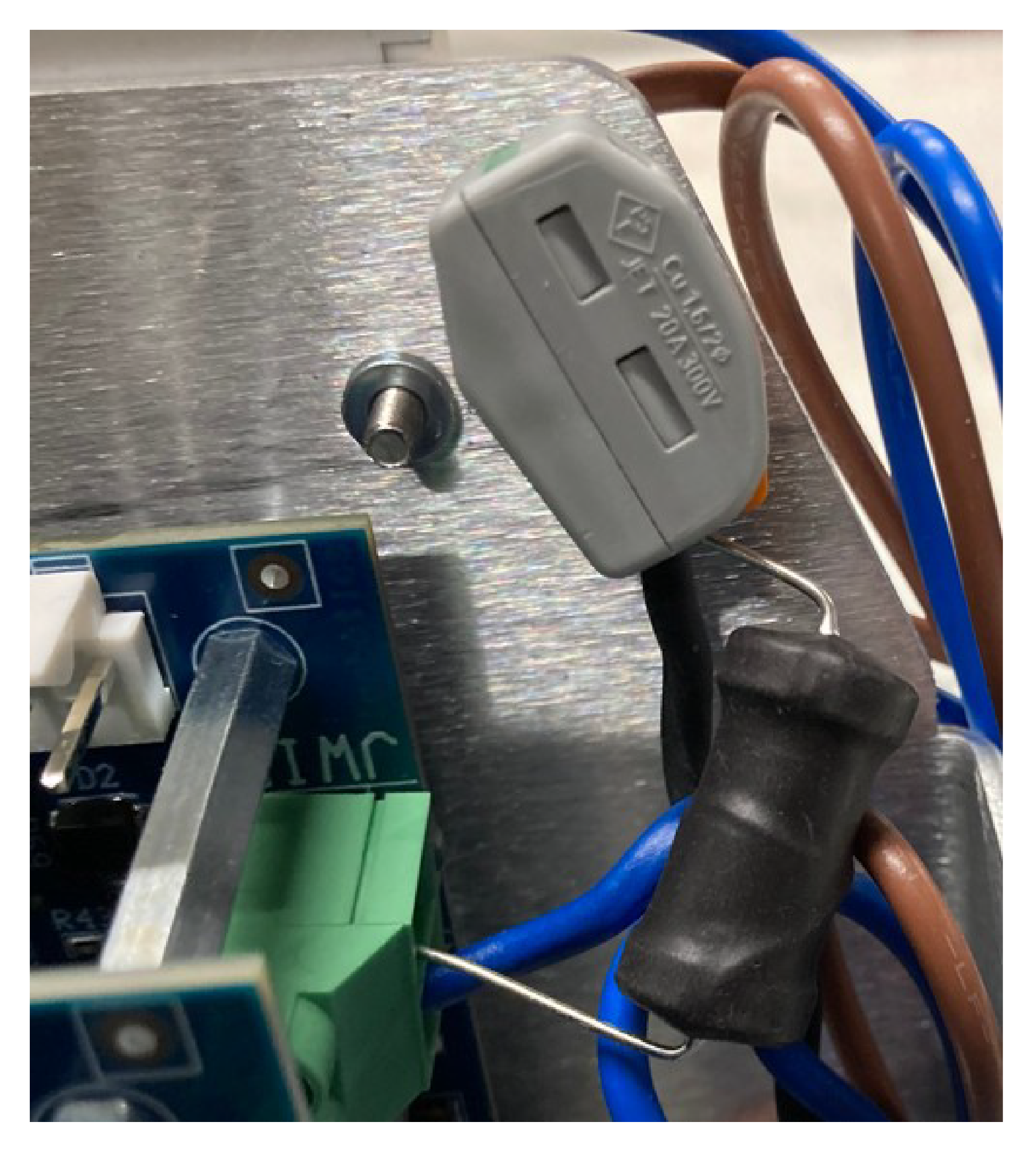
-
Place the
inductor in series with the peripheral wires. One end must be connected
to the station connection; the other must
be connected to the peripheral wire.
In the example
show in the following figure, an end of the inductor is connected
directly to the JWIRE connection on the ZL
card.
The other end
of the inductor is connected to a side of the 2-way connector. The
other end of the 2-way connector is connected
to the peripheral wire.