-
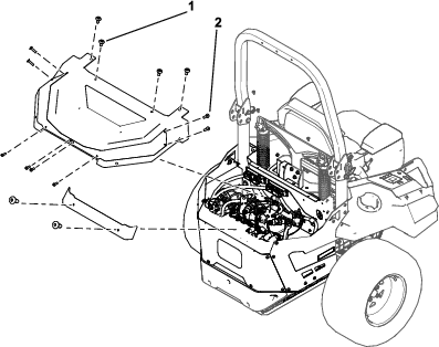
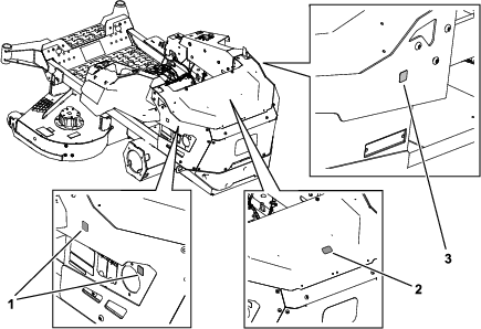
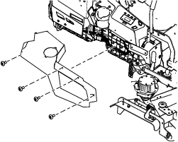
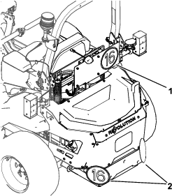
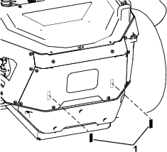
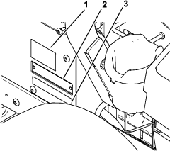
Remove the 4 Torx screws securing the side cover on
the right side of the machine. Repeat on the left side. Retain all
parts.
-
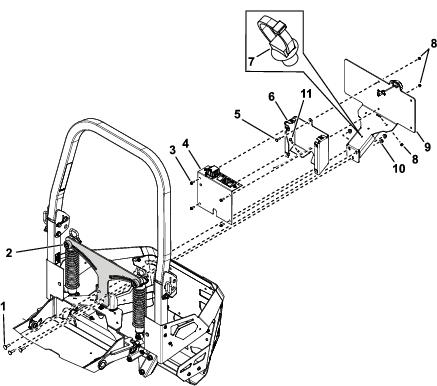
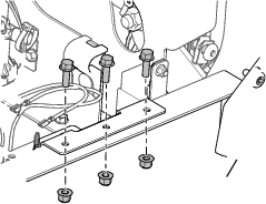
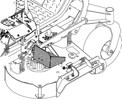
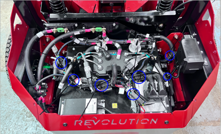
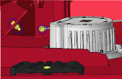
Remove the nut and bolt securing the electrical plate
cover and remove the cover. Retain all parts.
-
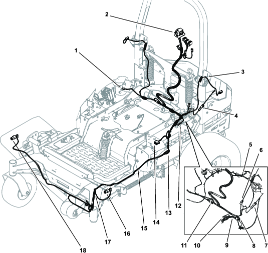
Starting from the back of the machine, lay the EU
Road light kit wire harness on to the license plate mount and light
assembly. Route the headlight, horn, and light switch connectors through
the left side.
Note: If machines have MyRIDE, route the harness through the opening.
-
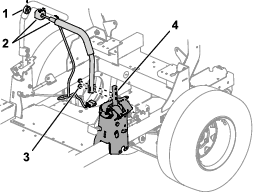
Route the headlight, horn, and light switch through
the left side of the chassis behind the console.
-
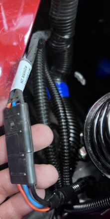
Connect the 12-pin connector on the EU Light kit wire
harness to the control lever assembly left connector.
-
Route the horn headlight cable on left side chassis
rail and under the toe board, avoiding interference with the MyRide
platform.
-
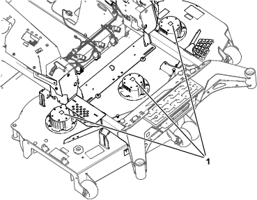
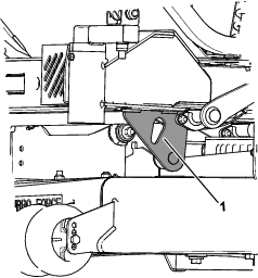
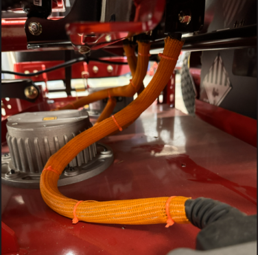
Route the harness along the height-of-cut bar at the
front of the machine and around the anchor point to the left chassis
rail interior below the operator platform.
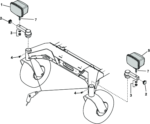
-
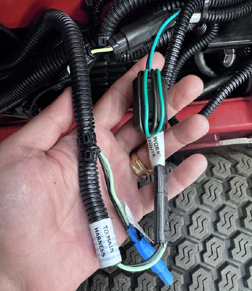
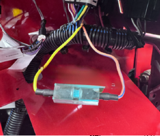
Identify the left and right front light connectors.
Mark the connectors.
Note: The right connector has blue, yellow, gray, and black wires.
The left connector has brown, yellow, grey, and black wires.
-
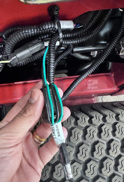
Route the front light connectors to their corresponding
lights.
-
Connect the front light connectors on the light kit
harness to the front lights. Ensure that the harness conduit is secure
to the shell.
-
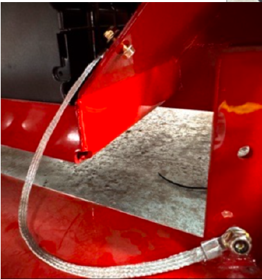
Connect the terminals white wire to (+), black wire
to (-).
Note: Due to the horn blocking access to the existing tie-down point,
the cords can be secured on the side of the chassis.
-
Lay the wiring harness connections to their approximate
positions at the machine rear.
-
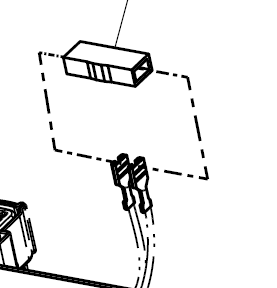
Connect the beacon wire harness to the beacon connector
on the light kit wire harness.
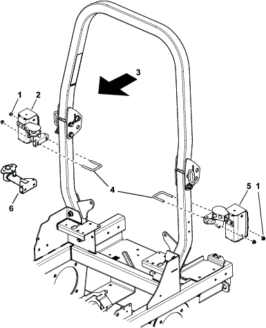
-
Route the left-rear light connector up the front of
the roll bar next to the beacon wire harness.
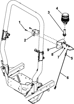
-
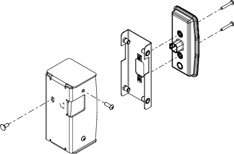
Route the connector through the rear light mount and
connect it to the rear light mount with 2 screws (#10 x 1-1/4 inches).
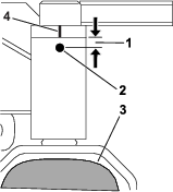
-
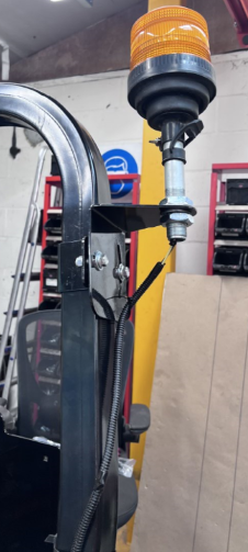
Secure the bracket height until the red light is approximately
90 cm (35 inches) above the ground.
-
Repeat the previous steps to install the rear right
light.
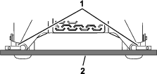
-
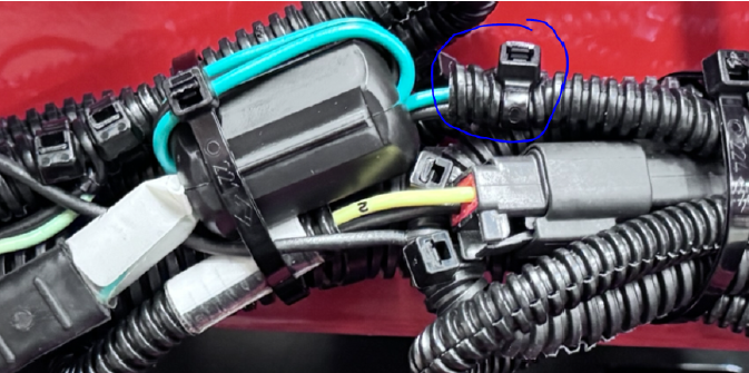
Secure the rear light leads and beacon harness to
the ROPS frame.
Note: Allow some slack in the beacon cable to allow the ROPS frame
to be folded.
-
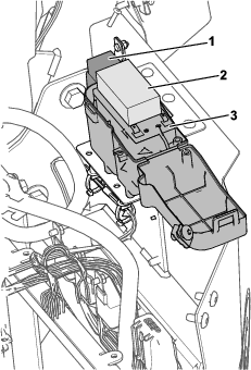
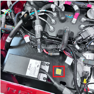
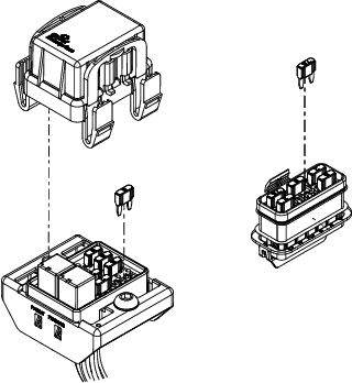
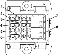
Open the main machine harness fuse box and remove
the fuse (5 A). Retain the fuse.
-
Install the mini-blade fuse (7.5 A) in place of the
fuse (5 A) and close the cover.
-
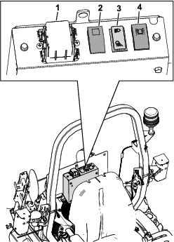
In the fuse box for the light-kit control panel, replace
the horn fuse (10 A) with the retained fuse (5 A). Ensure that the
control panel fuse box remains open.
-
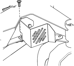
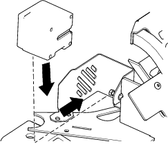
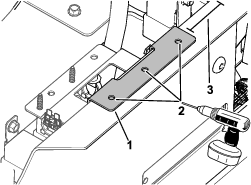
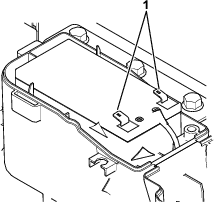
Install the fuse box to the control panel with 2 screws
(M6 x 16 mm). Close the fuse box cover.
-
In the control panel, connect each switch, flasher
unit, and license plate light.