
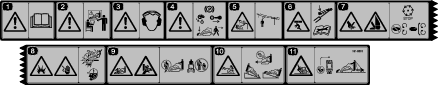
 , which means Caution, Warning,
or Danger—personal safety instruction. Failure to comply with
these instructions may result in personal injury or death.
, which means Caution, Warning,
or Danger—personal safety instruction. Failure to comply with
these instructions may result in personal injury or death.


 while
at the main screen. This will bring you to the main menu. Refer to
the following tables for a synopsis of the options available from
the menus:
while
at the main screen. This will bring you to the main menu. Refer to
the following tables for a synopsis of the options available from
the menus: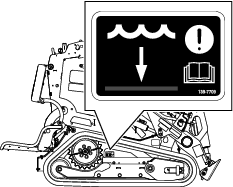

Maintenance
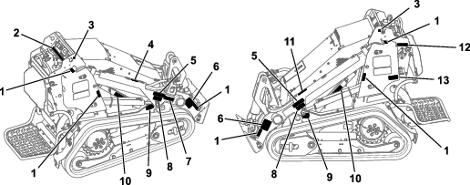
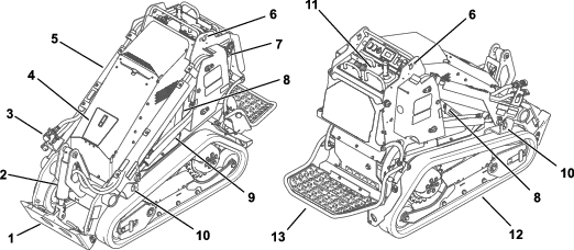
Note: Determine the left and right sides of the machine from the normal operating position.
Maintenance Safety
Caution
If you leave the key in the switch, someone could accidently start the machine and seriously injure you or other bystanders.
Remove the key from the switch before you perform any maintenance.
-
Park the machine on a level surface, disengage the auxiliary hydraulics, lower the attachment, ensure that the parking brake is engaged, shut off the machine, and remove the key. Wait for all movement to stop and allow the machine to cool before adjusting, cleaning, storing, or repairing it.
-
Do not allow untrained personnel to service the machine.
-
Use jack stands to support the components when required.
-
Carefully release pressure from components with stored energy; refer to Relieving Hydraulic Pressure.
-
Disconnect the battery before making any repairs; refer to Using the Battery-Disconnect Switch.
-
Keep your hands and feet away from the moving parts. If possible, do not make adjustments with the machine running.
-
Keep all parts in good working condition and all hardware tightened. Replace all worn or damaged decals.
-
Do not tamper with the safety devices.
-
Use only Toro-approved attachments. Attachments can change the stability and the operating characteristics of the machine. You may void the warranty if you use the machine with unapproved attachments.
-
Use only genuine Toro replacement parts.
-
If any maintenance or repair requires the loader arms to be in the raised position, secure the arms in the raised position with the hydraulic-cylinder lock(s).
-
Refer to local regulations for safely maintaining the machine and attach a warning tag to the control panel to inform others of ongoing maintenance.
Recommended Maintenance Schedule(s)
| Maintenance Service Interval | Maintenance Procedure |
|---|---|
| After the first 8 hours |
|
| After the first 50 hours |
|
| Before each use or daily |
|
| Every 25 hours |
|
| Every 50 hours |
|
| Every 100 hours |
|
| Every 400 hours |
|
| Every 500 hours |
|
| Every 1,000 hours |
|
| Every 1,500 hours or 2 years, whichever comes first |
|
| Yearly or before storage |
|
Pre-Maintenance Procedures
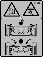
Using the Cylinder Locks
Warning
The loader arms may lower when in the raised position, crushing anyone under them.
Install the cylinder lock(s) before performing maintenance that requires raised loader arms.
Installing the Cylinder Locks
-
Remove the attachment.
-
Raise the loader arms to the fully raised position.
-
Shut off the machine and remove the key.
-
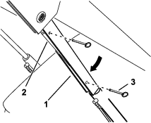
Position a cylinder lock over each lift-cylinder rod.
-
Secure each cylinder lock with 2 pins.
-
Slowly lower the loader arms until the cylinder locks contact the cylinder bodies and rod ends.
Removing and Storing the Cylinder Locks
Important: Remove the cylinder locks from the rods and fully secure them in the storage position before operating the machine.
-
Start the machine.
-
Raise the loader arms to the fully raised position.
-
Shut off the machine and remove the key.
-
Remove the pins securing each cylinder lock.
-
Remove the cylinder locks.
-
Place the cylinder locks on the posts on the sides of the machine and secure with the pins.
-
Lower the loader arms.
Accessing Internal Components
Warning
Opening or removing covers, hoods, and screens while the machine is running could allow you to contact moving parts, seriously injuring you.
Before opening any of the covers, hoods, and screens, shut off the machine, remove the key from the key switch, and allow the machine to cool.
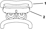
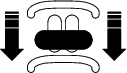
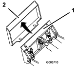
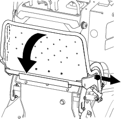
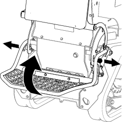
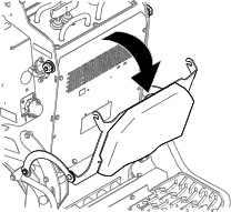
Releasing the Rear Cushion
-
Park the machine on a level surface.
-
Shut off the machine, remove the key, and wait for moving parts to stop.
-
Lower the platform.
-
Loosen the knobs on each side of the cushion.
-
Lower the cushion to the platform.
-
Perform any maintenance or adjustment on the machine.
-
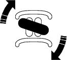
Raise the cushion, and slide it onto the pins on both sides of the machine.
-
Tighten the knobs.
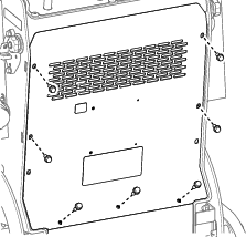
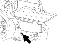
Removing the Rear Cover
-
Park the machine on a level surface.
-
Shut off the machine, remove the key, and wait for moving parts to stop.
-
Lower the platform.
-
Release the rear cushion.
-
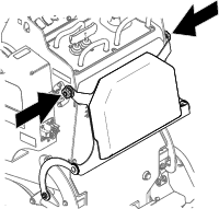
Remove the bolts securing the rear cover and remove the cover.
Lubrication
Greasing the Machine
| Maintenance Service Interval | Maintenance Procedure |
|---|---|
| Before each use or daily |
|
Grease Type: General-purpose grease
-
Park the machine on a level surface and lower the loader arms.
-
Shut off the machine and remove the key.
-
Clean the grease fittings with a rag.
-
Connect a grease gun to each fitting.
-
Pump grease into the fittings until grease begins to ooze out of the bearings (approximately 3 pumps).
-
Wipe up any excess grease.
Electrical System Maintenance
Electrical System Safety
-
Disconnect the battery before making any repairs; refer to Using the Battery-Disconnect Switch.
-
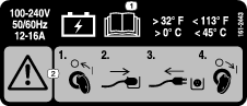
Charge the battery in an open, well-ventilated area, away from sparks and flames. Unplug the charger before connecting or disconnecting the battery. Wear protective clothing and use insulated tools.
-
Battery acid is poisonous and can cause burns. Avoid contact with skin, eyes, and clothing. Protect your face, eyes, and clothing when working with a battery.
-
Battery gases can explode. Keep cigarettes, sparks, and flames away from the battery.
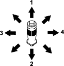
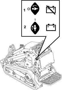
Using the Battery-Disconnect Switch
-
Park the machine on a level surface and lower the loader arms.
-
Shut off the machine and remove the key.
-
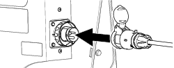
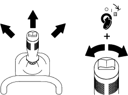
Turn the battery-disconnect switch to the ON or OFF position.
-
To energize the machine electrically, rotate the battery-disconnect switch clockwise to the ON position.
-
To de-energize the machine electrically, rotate the battery-disconnect switch counterclockwise to the OFF position.
-
Servicing the Lead-Acid Battery
| Maintenance Service Interval | Maintenance Procedure |
|---|---|
| Every 50 hours |
|
Removing the Battery
Warning
Incorrect battery cable routing could damage the machine and cables, causing sparks. Sparks could cause the battery gasses to explode, resulting in death or serious injury.
Always disconnect the negative (black) battery cable before disconnecting the positive (red) cable.
-
Park the machine on a level surface and lower the loader arms.
-
Shut off the machine and remove the key.
-
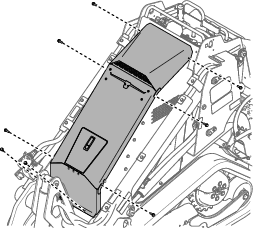
Remove the top cover assembly.
-
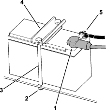
Disconnect the negative (black) ground cable from the battery post. Retain the fasteners.
-
Slide the rubber cover off the positive (red) cable.
-
Disconnect the positive (red) cable from the battery post. Retain the fasteners.
-
Remove the battery clamp.
-
Remove the battery.
Charging the Battery
Warning
Charging the battery produces gasses that could explode, resulting in death or serious injury.
Never smoke near the battery and keep sparks and flames away from battery.
Important: Always keep the battery fully charged (1.265 specific gravity). This is especially important to prevent battery damage when the temperature is below 0°C (32°F).
-
Remove the battery from the machine; refer to Removing the Battery.
-
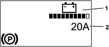
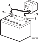
Charge the battery for 4 to 8 hours at a rate of 3 to 4 A (Figure 38). Do not overcharge the battery.
-
When the battery is fully charged, unplug the charger from the electrical outlet, then disconnect the charger leads from the battery posts (Figure 38).
Cleaning the Battery
Note: Keep the terminals and the entire battery case clean, to help extend battery life.
-
Park the machine on a level surface, lower the loader arms, and engage the parking brake.
-
Shut off the engine and remove the key.
-
Remove the battery from the machine; Removing the Battery.
-
Wash the entire case with a solution of baking soda and water.
-
Rinse the battery with clear water.
-
Coat the battery posts and cable connectors with Grafo 112X (skin-over) grease or petroleum jelly to prevent corrosion.
-
Install the battery; refer to Installing the Battery.
Installing the Battery
Warning
Incorrect battery cable routing could damage the machine and cables, causing sparks. Sparks could cause the battery gasses to explode, resulting in death or serious injury.
Always connect the positive (red) battery cable before connecting the negative (black) cable.
-
Place the battery on the battery tray and secure it with the clamp.
-
Using the fasteners previously removed, install the positive (red) battery cable to the positive (+) battery terminal.
-
Slide the red terminal boot onto the positive battery post.
-
Using the fasteners previously removed, install the negative (black) battery cable to the negative (-) battery terminal.
-
Install the top cover assembly.
Servicing a Replacement Battery
The original battery is maintenance-free and does not require service. For servicing a replacement battery, refer to the battery manufacturer’s instructions.
Servicing the Lithium-Ion Batteries
Note: The machine is equipped with 10 lithium-ion batteries.
A lithium-ion battery must be disposed of or recycled in accordance with local and federal regulations. If a battery requires service, contact your Authorized Service Dealer for assistance.
Do not open the battery. If you are having problems with a battery, contact your Authorized Service Dealer for assistance.
Maintaining the Lithium-Ion Batteries
Warning
The batteries contain high voltage, which could burn or shock you.
-
Do not attempt to open the batteries.
-
Use extreme care when handling a battery with a cracked case.
-
Use only the charger designed for the batteries.
The lithium-ion batteries hold a sufficient charge to perform intended work during its life span.
To achieve maximum life and use from your batteries, follow these guidelines:
-
Do not open the battery.
-
Store/park the machine in a clean, dry garage or storage area, away from direct sunlight, heat sources, rain, and wet conditions. Do not store it in a location where the temperature exceeds the range specified in Battery Storage Requirements.
Important: Temperatures outside of this range will damage your batteries. High temperatures during storage, especially at a high state of charge, reduces the life of the batteries.
-
When storing the machine for more than 10 days, ensure that the machine is in a cool and dry location, out of sunlight, rain, and wet conditions.
-
If you are using the machine hot conditions or in strong, direct sunlight, the battery may overheat. If this happens, a high-temperature alert appears on the InfoCenter and machine functionality may be reduced.
Immediately drive the machine to a cool location out of the sun, turn off the machine, and allow the batteries to cool fully before resuming operation. If the batteries continue to overheat, another alert appears on the InfoCenter and the machine will shut off.
-
Use lights only when it is necessary.
Maintaining the Battery Charger
Important: All electrical repairs should be performed by an Authorized Service Dealer only.
The charger requires little maintenance other than protecting it from damage and weather.
-
Coil the cord and place it into the storage compartment when not in use.
-
Periodically examine the cord for damage, and replace them when necessary with Toro-approved parts.
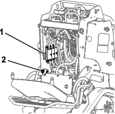
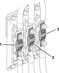
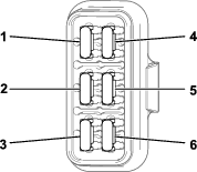
Servicing the Fuses
The electrical system is protected by fuses. It requires no maintenance. Refer to the traction unit Service Manual for information on testing and servicing the bolt-in fuses
-
Park the machine on a level surface and lower the loader arms.
-
Shut off the machine and remove the key.
-
Turn the battery-disconnect switch to the OFF position.
-
Release the rear cushion and remove the rear cover; refer to Removing the Rear Cover.
-
Replace fuses as needed.
-
Turn the battery-disconnect switch to the ON position.
-
Install the rear cover and the cushion.
Drive System Maintenance
Servicing the Tracks
| Maintenance Service Interval | Maintenance Procedure |
|---|---|
| After the first 8 hours |
|
| After the first 50 hours |
|
| Before each use or daily |
|
| Every 50 hours |
|
Cleaning the Tracks
-
Park the machine on a level surface.
-
With the bucket installed and angled downward, lower it into the ground so that the front of the traction unit lifts off the ground a few centimeters (inches).
-
Shut off the machine and remove the key.
-
Using a water hose or pressure washer, remove dirt from each track system.
Important: Ensure that you use high-pressure water to wash only the track area. Do not use a high-pressure washer to clean the rest of the traction unit. Do not use high-pressure water between the drive sprocket and the traction unit or you may damage the motor seals. High-pressure washing can damage the electrical system and hydraulic valves or deplete grease.
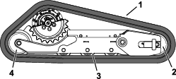
Important: Ensure that you fully clean the road wheels, front wheel, rear wheel, and drive sprocket. The road wheels should rotate freely when clean.
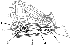
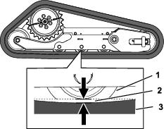
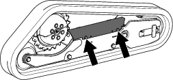
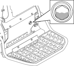
Checking and Adjusting the Track Tension
Lift/support 1 side of the machine and use the weight of the track to verify that the gap between the bottom of the road-wheel lip and the track is 19 mm (3/4 inch). If it is not, adjust the track tension using the following procedure.
-
Park the machine on a level surface and lower the loader arms.
-
Shut off the machine and remove the key.
-
Raise the side of the machine that you are adjusting so that the track is off the ground.
-
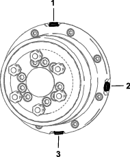
Loosen the bolts on the cover and remove the cover.
-
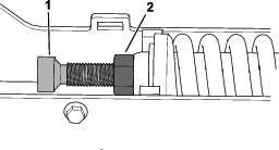
Loosen the jam nut and adjust the tensioning screw until the track deflection is 19 mm (3/4 inch).
-
Tighten the jam nut.
-
Install the cover and tighten the bolts.
-
Repeat the procedure for the other track.
-
Drive the machine, then park the machine on a level surface, shut off the machine, and remove the key.
-
Verify that the track deflection is 19 mm (3/4 inch). Adjust if necessary.
Replacing the Tracks
Removing the Tracks
-
Remove any attachments.
-
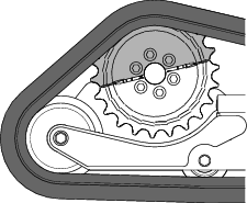
Park the machine on a level surface, ensuring that only 1 sprocket half is engaged with the track.
-
Lower the loader arms.
-
Shut off the machine and remove the key.
-
Raise the machine off the ground so that the bottom of the track is at least 10.2 cm (4 inches) off the ground. Support the machine using jack stands.
Note: Use jack stands rated for your machine.
Warning
Mechanical or hydraulic jacks may fail to support the machine and cause serious injury.
Use jack stands when supporting the machine.
-
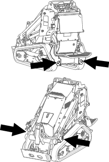
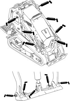
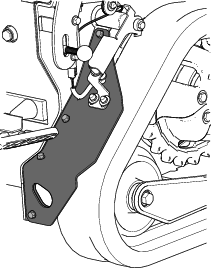
Remove and retain the 4 bolts securing the fender to the frame and remove the fender.
-
Loosen the bolts on the cover and remove the cover.
-
Loosen the jam nut and turn the tensioning screw to release the tension.
-
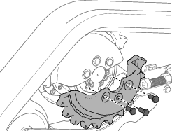
Remove the segment of the drive sprocket not engaged with the track.
Important: If you do not remove the sprocket segment, it may be difficult to install a new track without damaging it.
-
Start the machine and enable the traction control.
-
Move the traction control forward until the other half of the drive sprocket is not engaged with the track
-
Shut off the machine and remove the key.
-
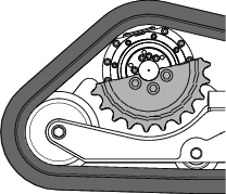
Remove the track from the track frame, drive hub, then front wheel.
Installing the Tracks
-
Wrap the new track around the front wheel.
-
Push the track under and between the road wheels and wrap it around the rear wheel.
-
Pry the track onto the drive hub.
-
Start the machine.
-
Move the traction control forward until the drive sprocket half engages with the track.
-
Shut off the machine and remove the key.
-
Apply thread-locking compound to the bolts of the drive sprocket half that you removed and install the sprocket half. Torque the bolts to 80 to 99 N∙m (59 to 73 ft-lb).
-
Adjust the tensioning screw until the track deflection is 19 mm (3/4 inch).
-
Tighten the jam nut.
-
Install the cover and tighten the bolts.
-
Install the fender to the machine using the retained bolts.
-
Repeat the procedure to replace the other track.
-
Lower the machine to the ground.
-
Drive the machine, then park the machine on a level surface, shut off the machine, and remove the key.
-
Verify that the track tension is correct; refer to Checking and Adjusting the Track Tension.
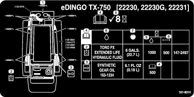
Drive-Motor Gear Oil Specifications
Oil type: Mobil SHC 75W-90
Capacity: 0.18 L (6.1 fl oz) per gearbox
Checking the Drive-Motor Gear Oil
-
Remove any attachments.
-
Park the machine on a level surface, ensuring that only 1 sprocket half is engaged with the track.
-
Shut off the machine and remove the key.
-
Raise the machine off the ground so that the tracks are off the ground. Support the machine using jack stands.
Note: Use jack stands rated for your machine. Refer to the Specifications for the weight.
Warning
Mechanical or hydraulic jacks may fail to support the machine and cause serious injury.
Use jack stands when supporting the machine.
-
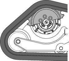
Remove the segment of the drive sprocket not engaged with the track.
-
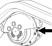
Remove the check plug and verify that the oil is at the bottom of the hole.
-
If the level is low, add fluid as follows:
-
Remove the track; refer to Removing the Tracks.
-
Remove the second sprocket.
-
Remove the fill plug.
-
Fill the drive motor with gear oil until it reaches the bottom of the check hole.
-
Install the fill and check plugs.
-
-
Repeat the steps 5 through 7 for the other drive motor.
-
Start the machine and engage the traction control for a few minutes.
-
Shut off the machine and remove the key.
-
Remove the check plugs from both traction motors and verify that the oil level is at the bottom of the hole.
-
Install the plugs and torque them to 5 to 6 N∙m (50 to 60 in-lb).
-
Apply thread-locking compound to the bolts of the lower drive sprocket and install the sprocket. Torque the bolts to 80 to 99 N∙m (59 to 73 ft-lb).
-
Install the tracks, if removed; refer to Installing the Tracks.
-
Lower the machine to the ground.
Changing the Drive-Motor Gear Oil
| Maintenance Service Interval | Maintenance Procedure |
|---|---|
| After the first 50 hours |
|
| Every 500 hours |
|
-
Remove any attachments.
-
Start the engine and drive the machine for 5 minutes.
Note: This warms the gear oil so that it drains better.
-
Park the machine on a level surface, ensuring that only 1 sprocket half is engaged with the track.
-
Shut off the machine and remove the key.
-
Remove the track; refer to Removing the Tracks.
-
Remove the second sprocket.
-
Place a drain pan under the drive motor.
-
Remove the fill and drain plugs and allow the gear oil to drain.
-
Install the drain plug.
-
Remove the fill plug and fill the drive motor with gear oil until the oil starts dripping from the check hole; refer to Drive-Motor Gear Oil Specifications..
-
Install the fill and check plugs.
-
Repeat the procedure for the other drive motor.
-
Start the machine and engage the traction control for a few minutes.
-
Shut off the machine and remove the key.
-
Remove the check plugs from both traction motors and verify that the oil level is at the bottom of the hole.
-
Install the plugs and torque them to 5 to 6 N∙m (50 to 60 in-lb).
-
Apply thread-locking compound to the bolts of the lower drive sprocket half and install the sprocket half. Torque the bolts to 80 to 99 N∙m (59 to 73 ft-lb).
-
Install the tracks; refer to Installing the Tracks.
-
Lower the machine to the ground.
Controls System Maintenance
Adjusting the Controls
The factory adjusts the controls before shipping the machine. However, after many hours of use, you may need to adjust the traction control alignment, the NEUTRAL position of the traction control, and the tracking of the traction control in the full forward position.
Contact your Authorized Service Dealer to adjust the controls of your machine.
Hydraulic System Maintenance
Hydraulic System Safety
-
Seek immediate medical attention if fluid is injected into skin. Injected fluid must be surgically removed within a few hours by a doctor.
-
Ensure that all hydraulic-fluid hoses and lines are in good condition and all hydraulic connections and fittings are tight before applying pressure to the hydraulic system.
-
Keep your body and hands away from pinhole leaks or nozzles that eject high-pressure hydraulic fluid.
-
Use cardboard or paper to find hydraulic leaks.
-
Safely relieve all pressure in the hydraulic system before performing any work on the hydraulic system.
Relieving Hydraulic Pressure
To relieve hydraulic pressure while the machine is on, disengage the auxiliary hydraulics and fully lower the loader arms; turn the key switch to the AUXILIARY HYDRAULIC RELIEF position and press the auxiliary-hydraulic switch back and forth.
To relieve hydraulic pressure while the machine is off, turn the key switch to the AUXILIARY HYDRAULIC RELIEF position and press the auxiliary-hydraulic switch back and forth.
Lowering the Loader Arms Without Power
-
Park the machine on a level surface.
-
Shut off the machine and remove the key.
-
Release the cushion and remove the rear cover; refer to Removing the Rear Cover.
-
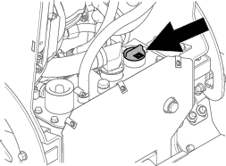
Loosen the bypass valve.
-
Lower the loader arms.
-
Tighten the bypass valve.
-
Install the rear cover and the cushion.
Hydraulic Fluid Specifications
| Maintenance Service Interval | Maintenance Procedure |
|---|---|
| Every 100 hours |
|
Hydraulic Tank Capacity: 22.7 L (6 US gallons)
Recommended hydraulic fluid: Toro PX Extended Life Hydraulic Fluid
Note: A machine using the recommended replacement fluid requires less frequent fluid and filter changes.
Alternative hydraulic fluids: If Toro PX Extended Life Hydraulic Fluid is not available, you may use another conventional, petroleum-based hydraulic fluid having specifications that fall within the listed range for all the following material properties and that it meets industry standards. Do not use synthetic fluid. Consult with your lubricant distributor to identify a satisfactory product.
Note: Toro does not assume responsibility for damage caused by improper substitutions, so use products only from reputable manufacturers who will stand behind their recommendation.
| Material Properties: | ||
| Viscosity, ASTM D445 | cSt @ 40°C (104°F) 44 to 48 | |
| Viscosity Index ASTM D2270 | 140 or higher | |
| Pour Point, ASTM D97 | -37°C to -45°C (-34°F to -49°F) | |
| Industry Specifications: | Eaton Vickers 694 (I-286-S, M-2950-S/35VQ25 or M-2952-S) | |
Note: Many hydraulic fluids are almost colorless, making it difficult to spot leaks. A red dye additive for the hydraulic fluid is available in 20 ml (0.67 fl oz) bottles. A bottle is sufficient for 15 to 22 L (4 to 6 US gallons) of hydraulic fluid. Order Part No. 44-2500 from your Authorized Service Dealer.
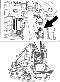
Checking the Hydraulic-Fluid Level
| Maintenance Service Interval | Maintenance Procedure |
|---|---|
| Every 25 hours |
|
Check the hydraulic-fluid level before the machine is first started and after every 25 operating hours.
Refer to Hydraulic Fluid Specifications.
Important: Always use the correct hydraulic fluid. Unspecified fluids will damage the hydraulic system.
-
Park the machine on a level surface and lower the loader arms.
-
Shut off the machine, remove the key, and allow the machine to cool.
-
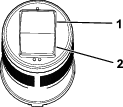
Look into the glass bubble near the platform. If the hydraulic fluid fills less than half of the bubble, add fluid as follows:
-
Remove the rear cover; refer to Removing the Rear Cover.
-
Clean the area around the filler cap and remove it.
-
Add hydraulic fluid until it fills half of the glass bubble.
-
Install the filler cap.
-
Install the rear cover.
-
Replacing the Hydraulic Filter
| Maintenance Service Interval | Maintenance Procedure |
|---|---|
| Every 500 hours |
|
-
Park the machine on a level surface and lower the loader arms.
-
Shut off the machine, remove the key, and allow the machine to cool.
-
Remove the rear cover; refer to Removing the Rear Cover.
-
Remove and discard the old filter.
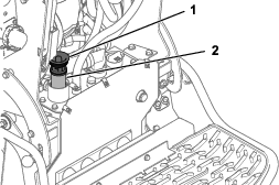
-
Install the replacement hydraulic filter and filler cap and torque the bolt on top to 13 to 15.5 N∙m (110 to 140 in-lb).
-
Clean up any spilled fluid.
-
Start the machine and let it run for about 2 minutes to purge air from the system.
-
Shut off the machine and check for leaks.
-
Check the fluid level in the hydraulic tank; refer to Checking the Hydraulic-Fluid Level. Add hydraulic fluid until it is visible in the glass bubble.
-
Install the rear cover.
Changing the Hydraulic Fluid
| Maintenance Service Interval | Maintenance Procedure |
|---|---|
| Every 400 hours |
|
| Every 1,000 hours |
|
-
Park the machine on a level surface and lower the loader arms.
-
Shut off the machine, remove the key, and allow the machine to cool.
-
Remove the rear cover; refer to Removing the Rear Cover.
-
Place a large drain pan under the machine that can hold the fluid capacity listed in Hydraulic Fluid Specifications.
-
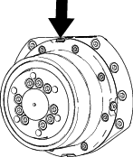
Remove the drain plug from the bottom of the hydraulic tank and allow the fluid to completely drain.
-
Install the drain plug.
-
Fill the hydraulic tank with hydraulic fluid; refer to Hydraulic Fluid Specifications.
Note: Dispose of used fluid at a certified recycling center.
-
Install the rear cover.
Cleaning
Removing Debris
| Maintenance Service Interval | Maintenance Procedure |
|---|---|
| Before each use or daily |
|
Warning
Using compressed air improperly to clean the machine could result in serious injury.
-
Wear appropriate personal protective equipment, such as eye protection, hearing protection, and a dust mask.
-
Do not aim compressed air at any part of your body or at anyone else.
-
Refer to the manufacturer’s instructions for the air compressor for operating and safety information.
-
Park the machine on a level surface, remove any attachment, raise the loader arms, and install the cylinder locks.
-
Shut off the machine and remove the key.
-
Clean any debris from the machine.
Important: Blow the dirt out rather than wash it out. If you use water, keep it away from electrical items and hydraulic valves. Clean electrical connectors using compressed air; do not use contact cleaner.
-
Remove and store the cylinder locks and lower the loader arms.
Washing the Machine
If you must pressure wash the machine, do the following:
Important: Do not clean the machine with water while it is charging. Ensure machine is dry before charging.
-
Wear appropriate personal protective equipment for the pressure washer.
-
Keep all guards in place on the machine.
-
Avoid spraying at electronic components.
-
Avoid spraying at edges of decals.
-
Spray the exterior of the machine only. Do not spray directly into openings in the machine.
-
Spray only the dirty parts of the machine.
-
Use a 40-degree or larger spray nozzle. 40-degree nozzles are usually white.
-
Keep the tip of the pressure washer at least 61 cm (2 ft) away from the surface being washed.
-
Use only pressure washers with pressure below 13,790 kpa (2,000 psi) and flow below 7.6 L (2 US gallons) per minute.
-
Replace damaged or peeling decals.
-
Grease all grease points after washing; refer to Greasing the Machine.