This kit contains parts to install a new Briggs & Stratton Vanguard® battery (which replaces the existing Samsung® battery and associated parts) to the Greensmaster traction unit.
Safety
Safety and Instructional Decals
 |
Safety decals and instructions are easily visible to the operator and are located near any area of potential danger. Replace any decal that is damaged or missing. |



Installation
Caution
Removing or installing the batteries may result in personal injury and property damage.
When removing or installing the batteries, follow these recommendations:
-
Always disconnect the main-power connectors when servicing products with lithium-ion batteries.
-
Always service lithium-ion batteries with the machine parked near a service door large enough to move the product or battery outside in case of an emergency, and keep a fire blanket nearby. Do not use a fire extinguisher on lithium-ion batteries.
-
Do not allow the battery terminals or battery cables to touch any metal parts of the machine.
-
Do not allow metal tools to short between the battery terminals or battery cables and metal parts of the machine.
-
Do not attach anything to the battery terminal other than the battery cable or wire harness connector that came with the product.
-
Always keep the battery retainers and covers in place to protect and secure the batteries.
Preparing the Machine
-
Park the machine on a level surface.
-
Engage the parking brake.
-
Shut off the machine.
-
Disconnect the battery; refer to your Operator’s Manual.
Removing the Existing Battery
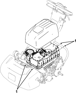
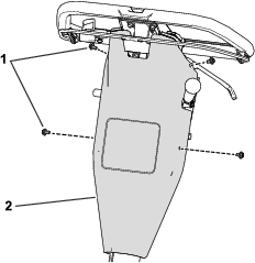
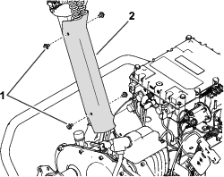
Remove the Battery Cover, Control Cover, and Cable Cover
Removing the Existing Samsung Battery, Battery Controller, and Wire Harness
-
Cut the cable ties that secure the existing wire harness to the machine and remove the wire harness from the machine.
Important: Record the existing wire-harness routing and connection locations at the handle; use this as a reference for routing and connecting the new wire harness to the control connectors at the handle.
-
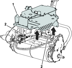
Remove the battery controller (BMS) and the Samsung battery from the machine; refer to the machine Service Manual for removal instructions.
Installing the Battery Tray
Parts needed for this procedure:
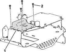
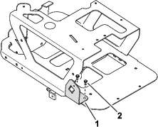
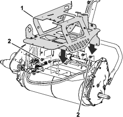
| Battery tray | 1 |
| Bolt (5/16 inch) | 4 |
| Bolt (#10) | 2 |
| Battery-connector mount plate | 1 |
Installing the Wire Harness
Parts needed for this procedure:
| Wire harness | 1 |
| Flying lead | 1 |
| Bolt (#10) | 1 |
| Connector handle | 1 |
| Screw | 3 |
| Locknut | 3 |
| Clamp | 4 |
| Bolt (1/4 x 3/4 inch) | 2 |
| Cable tie | 5 |
| Push fastener | 2 |
| Battery | 1 |
| Bolt (#10) | 4 |
| Battery-cover mount plate | 1 |
| Battery hold bracket | 1 |
| Bolt (1/4 x 1 inch) | 2 |
| Bolt (#8) | 2 |
| CAN gateway | 1 |
Wire-Harness Routing Overview
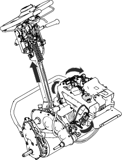
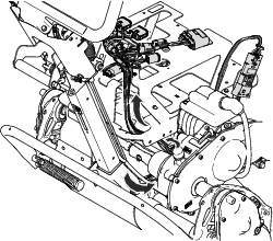
Figure 8 shows an overview of the wire harness installed to the machine. The harness is routed up to the controls on the handle and to connections on the battery tray. Refer to the following procedures for instructions to install the wire-harness connections.
Connecting the Wire Harness at the Handle
-
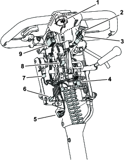
Route the wire-harness connectors with control labels (e.g., ignition switch, traction switch, and throttle sensor) toward the handle and connect all of the wire-harness connectors to the corresponding controls at the handle (Figure 9).
Refer to the wire-harness labels and your previously recorded references from disconnecting the existing wire harness.
-
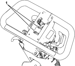
Install 2 cable ties to the wire-harness section with the connector labeled INFOCENTER (Figure 10) so that the wire harness is away from the bail link.
-
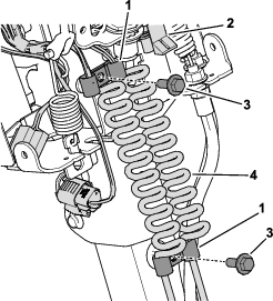
Use 4 clamps and 2 bolts (1/4 x 3/4 inch) to secure the upper and lower coiled areas of the wire harness to the handle (Figure 11).
-
Install a cable tie around the connector labeled TRACTION SWITCH (Figure 11) so that it is secured to the control frame.
Routing the Wire Harness to the Battery Tray
Connecting the Wire Harness at the Battery Tray
-
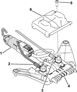
Install the black ring terminal, red ring terminal and wire-harness connector labeled VANGUARD BATTERY INTERFACE to the flying lead as shown in Figure 13.
-
Torque the nuts that secure the ring terminals to the flying lead to 5.6 to 6.2 N∙m (50 to 55 in-lb).
-
Torque the screw for the cover to 3.3 to 4 N∙m (30 to 35 in-lb).
-
-
Slide the battery into the battery tray (Figure 14).
Ensure that the battery is against the rear base plate and the battery interface panel (Figure 14) is facing towards the front of the machine.
-
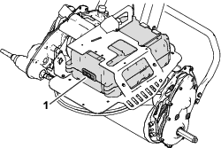
Install the flying lead to the battery slot (Figure 15).
Torque the battery-mount bolts to 5.6 to 6.2 N∙m (50 to 55 in-lb).
-
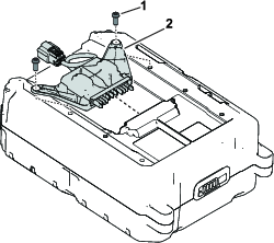
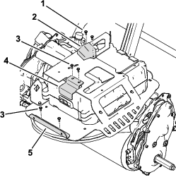
Use 4 bolts (#10) to secure the following items to the battery tray (Figure 16):
-
Battery-cover mount plate
-
Battery hold bracket
-
-
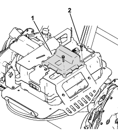
Use 2 bolts (#8) to secure the CAN gateway to the battery tray (Figure 16).
Torque the bolts to 3.3 to 4.5 N∙m (30 to 40 in-lb).
-
Use 2 bolts (1/4 x 1 inch) to secure the battery controller to the battery tray (Figure 17).
-
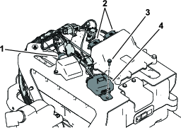
Connect the wire harness to the CAN gateway and the battery controller (Figure 18).
-
Use a bolt (#10) to secure the fuse block to the battery tray (Figure 18).
-
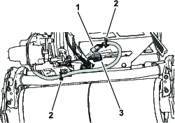
Under the battery tray, connect the wire-harness connectors labeled REEL MOTOR to the electric-motor connectors (Figure 19).
-
Use 2 push fasteners to secure the electric-motor cable to the battery tray (Figure 19).
-
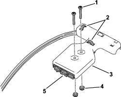
Use 2 screws and 2 locknuts to secure the connector handle to the Anderson connector labeled BATTERY INTERCONNECT (WITH HANDLE) on the wire harness (Figure 20).
-
Secure 2 cable ties around the wire harness and connector handle (Figure 20).
-
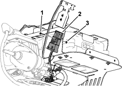
Use a screw and a locknut to secure the Anderson connector labeled BATTERY INTERCONNECT (MOUNTED) to the battery-connector mount plate (Figure 21).
Installing the Battery Cover, Control Cover, and Cable Cover
Parts needed for this procedure:
| Bolt (#10) | 4 |
| Washer | 4 |
-
Use the previously removed bolts to install the control cover and cable cover to the machine.
-
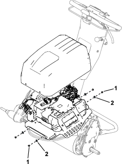
Use 4 bolts (#10) and 4 washers to secure the battery cover to the battery tray (Figure 22).
Using Toro DIAG to Update the Software
-
Connect Toro DIAG to the machine; refer to the Toro DIAG Software User’s Guide and the Toro DIAG Commercial Product User’s Guide.
-
Update the model number to 04875 and the serial number to the appropriate serial number for your Battery Replacement Kit.
-
This step is completed while Toro DIAG is attempting to retrieve the machine model number and serial number; refer to the Establish Communication with the Machine section in the Toro DIAG Software User’s Guide.
-
Ensure that the software revision level for the batteries is updated by selecting the REPROGRAM button in Toro DIAG; refer to the Toro DIAG Software User’s Guide.
Charging the Batteries
Refer to your authorized Toro distributor for the appropriate battery charger for your machine. Use the battery charger to charge the batteries; refer to the battery charging instructions in the Greensmaster e1021, e1026, and eFlex® 1021 Greensmower (Model 04835, 04845, and 04865) Operator’s Manual.