
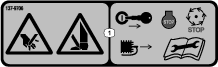
 , which means Caution, Warning,
or Danger—personal safety instruction. Failure to comply with
these instructions may result in personal injury or death.
, which means Caution, Warning,
or Danger—personal safety instruction. Failure to comply with
these instructions may result in personal injury or death.


Maintenance
Note: Determine the left and right sides of the machine from the normal operating position.
Accessing the Cutting Unit
Access the bedknife and reel for maintenance as follows:
-
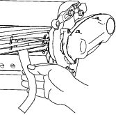
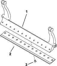
With the cutting unit removed from the machine, prop up the rear of the cutting unit to ensure that the nuts on the back end of the bedbar adjusting screws are not resting on the work surface (Figure 11).
-
With the cutting unit attached to the machine, lower the traction-unit handle to the ground (Figure 12).

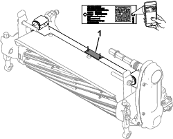
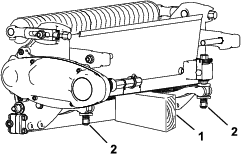
Checking the Reel-Driveshaft Grease Point
| Maintenance Service Interval | Maintenance Procedure |
|---|---|
| Yearly |
|
-
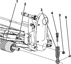
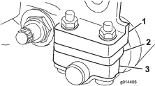
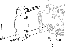
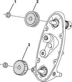
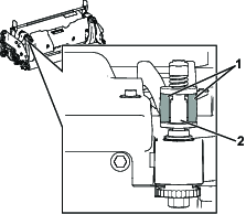
Remove the hardware that secures the reel-drive assembly to the side plate (Figure 13).
-
Remove the nuts from the inside of the side plate (Figure 13).
-
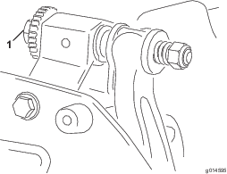
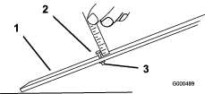
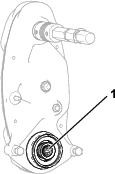
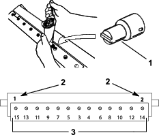
Check the inside of the reel driveshaft (Figure 14) for any remaining grease.
If you do not see a sufficient amount of grease, add more grease to the male and female spline shaft.
-
Use the previously removed socket-head screws and nuts to secure the reel-drive assembly to the side plate.
-
Install the cutting unit to the traction unit; refer to your traction unit Operator’s Manual.
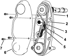
Adjusting the Reel Drive Belt Tension
| Maintenance Service Interval | Maintenance Procedure |
|---|---|
| Yearly |
|
-
Remove the cover from the reel drive housing by removing the 4 screws holding it in place.
-
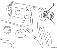
Loosen the idler-arm bolt and rotate the idler arm to remove tension from the belt.
-
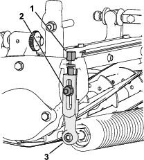
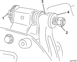
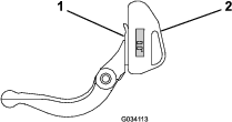
Use a beam-style torque wrench to apply 6 to 7 N∙m (55 to 60 in-lb) of force to the upper idler-arm internal screw (Figure 15).
-
Tighten the idler-arm bolt to secure the idler arm.
-
Install the cover with the 4 corresponding screws.
Adjusting the Clip Rate
The clip rate is determined by the following machine settings:
-
Reel speed: The reel speed can be adjusted to a high or low setting; refer to your traction unit Operator’s Manual.
-
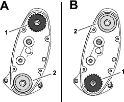
Reel-drive-pulley position: The reel-drive pulleys (22-tooth and 24-tooth) can be set in 2 positions:
Note: The pulley position is set to the LOW position from the factory.
To adjust the position of the pulleys, refer to the following steps:
-
Remove the belt cover to expose the belt (Figure 17).
-
Loosen the idler-arm bolt and rotate the idler arm (Figure 17) to release tension on the belt.
-
Remove the belt (Figure 17).
-
Loosen the nut on each pulley, remove the pulleys, and use the nuts to install the pulleys in your desired configuration.
-
Torque the pulley nuts to 37 to 45 N∙m (27 to 33 ft-lb)
-
Install the belt and tension the belt by applying 6 to 7 N∙m (55 to 60 in-lb) to the idler-arm internal hex shown in Figure 17.
-
Tighten the idler-arm bolt and install the belt cover.
Bedknife Specifications
Servicing the Bedknife
Only a properly trained mechanic should service the bedbar and bedknife to prevent damage to the reel, bedbar, or bedknife. Ideally, take the cutting unit to your authorized Toro distributor for service. Refer to the Service Manual for your traction unit for complete instructions, special tools, and diagrams for servicing the bedknife. Should you ever need to remove or assemble the bedbar yourself, instructions are provided below, as are the specifications for servicing the bedknife.
Important: Always follow the bedknife procedures detailed in your Service Manual when servicing the bedknife. Failure to install and grind the bedknife correctly can lead to damage to the reel, bedbar, or bedknife.
Removing the Bedbar/Bedknife Assembly
-
Turn the bedbar adjusting-screw counterclockwise to back the bedknife away from the reel (Figure 19).
-
Back out the spring-tension nut until the washer is no longer tensioned against the bedbar (Figure 19).
-
On each side of the machine, loosen the locknut shown in Figure 20.
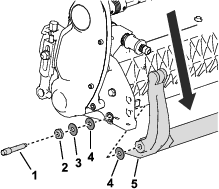
-
Remove each bedbar bolt, allowing the bedbar to be pulled downward and removed from the cutting unit (Figure 20).
Account for the 2 plastic washers and 1 steel washer on each end of the bedbar (Figure 20).
-
Remove the bedknife from the bedbar by removing all screws holding it in place. Use a socket wrench with the Bedknife Screw Tool (Part No. TOR510880).
Note: You may use a mechanical or pneumatic impact wrench to loosen the bedknife screws.
Note: Discard the bedknife and screws.
Installing the New Bedknife
-
Select a new bedknife per the Height-of-Cut and Bedknife Selection Charts.
-
Remove the rust, scale, and corrosion from the bedbar surface and apply a thin layer of oil to the bedbar surface.
Important: Do not remove casting material from the bedbar. The bedbar is concave in the middle by design; do not grind.
-
Clean the threads in the bedbar.
-
Apply anti-seize compound on the new bedknife screws and install the bedknife on the bedbar.
Important: Only use new bedknife screws.
Note: The quantity of screws varies depending on the bedbar.
-
Torque the 2 outer screws to 1 N∙m (10 in-lb).
-
Working from the center of the bedknife, torque the screws to 25.9 +/- 1.4 N∙m (19 +/- 1 ft-lb).
Important: Do not tighten the bedknife screws using a mechanical or pneumatic impact wrench.
-
Grind the new bedknife; refer to Bedknife Grinding Specifications.
Bedknife Grinding Specifications
| Bedknife Relief (Top) Angle | See Height-of-Cut and Bedknife Selection Charts. |
| Front Angle Range | 13° to 17° |
| Fairway Bedknife Front Angle | 10° |
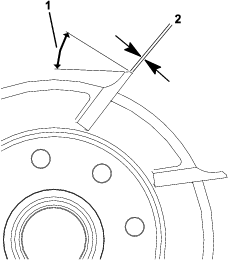
Checking the Top Grind Angle
The angle that you use to grind your bedknives is very important.
Use the angle indicator (Toro Part No. 131-6828) and the angle-indicator mount (Toro Part No. 131-6829) to check the angle that your grinder produces and then correct for any grinder inaccuracy.
-
Place the angle indicator on the bottom side of the bedknife as shown in Figure 24.
-
Press the Alt Zero button on the angle indicator.
-
Place the angle-indicator mount on the edge of the bedknife so that the edge of the magnet mates with the edge of the bedknife (Figure 25).
Note: The digital display should be visible from the same side during this step as it was in step 1.
-
Place the angle indicator on the mount as shown in Figure 25.
Note: This is the angle that your grinder produces, and should be within 2 degrees of the recommended top grind angle.
Installing the Bedbar/Bedknife Assembly
-
Install the bedbar/bedknife assembly, positioning the mounting ears between the washers and the bedbar-adjusting screw (Figure 26).
Important: Center the DPA adjusters in the bedbar ears as shown in Figure 26.If DPA adjusters are installed against the bedbar ears, this may negatively affect the bedknife-to-reel contact.
-
Secure the bedbar to each side plate with the bedbar bolts (nuts on bolts) and 3 washers (6 total).
-
Position a nylon washer on each side of the side-plate boss. Place a steel washer outside each of the nylon washers (Figure 27).
-
Torque the bedbar bolts to 27 to 36 N∙m (20 to 27 ft-lb).
-
Tighten the locknuts until you remove the end play from steel washers, but you are able to rotate them by hand. The washers on the inside may have a gap.
Important: Do not overtighten the locknuts or they will deflect the side plates.
-
Tighten the spring tension nut until the spring is collapsed, then back it off 1/2 turn (Figure 27).
-
Adjust the bedknife to the reel; refer to Adjusting the Bedknife to the Reel.
Reel Specifications
Preparing the Reel for Grinding
-
Ensure that all cutting unit components are in good condition and correct any issues before grinding.
-
Follow the reel grinder manufacturer’s instructions to grind the cutting reel to the following specifications.
Reel Grinding Specifications New Reel Diameter 128.5 mm (5.06 inches) Reel Diameter Service Limit 114.3 mm (4.50 inches) Blade Relief Angle 30° ± 5° Blade Land Width Range 0.8 to 1.2 mm (0.03 to 0.05 inches) Reel Diameter Taper Service Limit 0.25 mm (0.010 inch)
Relief-Grinding the Reel
The new reel has a land width of 0.8 to 1.2 mm (0.03 to 0.05 inch) and a 30° relief grind.
When the land width gets larger than 3 mm (0.120 inch) wide, do the following:
-
Apply a 30° relief grind on all reel blades until the land width is 0.8 mm (0.03 inch) wide
-
Spin grind the reel to achieve <0.025 mm (0.001 inch) reel run-out.
Note: This causes the land width to grow slightly.
-
Adjust the cutting unit; refer to your cutting unit Operator’s Manual.
Note: To extend the longevity of the sharpness of the edge of the reel and the bedknife—after grinding the reel and/or the bedknife—check the reel to bedknife contact again after cutting 2 greens, as any burrs will be removed. Burrs may create improper reel to bedknife clearance, which can accelerate wear.
Backlapping the Cutting Unit
To backlap the cutting unit, use the Access Backlap Kit (Model No. 139-4342); refer to the operating instructions in the kit Installation Instructions. Contact your authorized Toro distributor to acquire this kit.