Introduction

This cutting unit is intended to be used by professional, hired operators in commercial applications. It is designed for cutting grass on well-maintained lawns in golf courses, parks, sports fields, and on commercial grounds. Using this product for purposes other than its intended use could prove dangerous to you and bystanders.

Read this information carefully to learn how to operate and maintain your product properly and to avoid injury and product damage. You are responsible for operating the product properly and safely.

Visit www.Toro.com for product safety and operation training materials, accessory information, help finding a dealer, or to register your product.

Whenever you need service, genuine Toro parts, or additional information, contact an Authorized Service Dealer or Toro Customer Service and have the model and serial numbers of your product ready. Figure 1 identifies the location of the model and serial numbers on the product. Write the numbers in the space provided.

Important: With your mobile device, you can scan the QR code on the serial number plate (if equipped) to access warranty, parts, and other product information.

g280515

This manual identifies potential hazards and has safety messages identified by the safety-alert symbol (Figure 2), which signals a hazard that may cause serious injury or death if you do not follow the recommended precautions.

g000502

This manual uses 2 words to highlight information. Important calls attention to special mechanical information and Note emphasizes general information worthy of special attention.

This product complies with all relevant European directives. For details, please see the Declaration of Incorporation (DOI) at the back of this publication.

Safety

General Safety

This product is capable of amputating hands and feet. Always follow all safety instructions to avoid serious personal injury.

  • Read and understand the contents of this Operator’s Manual before starting the machine.

  • Use your full attention while operating the machine. Do not engage in any activity that causes distractions; otherwise, injury or property damage may occur.

  • Do not put your hands or feet near moving components of the machine.

  • Do not operate the machine without all guards and other safety protective devices in place and functioning properly on the machine.

  • Keep clear of any discharge opening.

  • Keep bystanders and children out of the operating area. Never allow children to operate the machine.

  • Before you leave the operator’s position, do the following:

    • Park the machine on a level surface.

    • Lower the cutting unit(s).

    • Disengage the drives.

    • Engage the parking brake (if equipped).

    • Shut off the engine and remove the key.

    • Wait for all movement to stop.

Improperly using or maintaining this machine can result in injury. To reduce the potential for injury, comply with these safety instructions and always pay attention to the safety-alert symbolGraphic
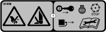
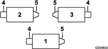
, which means Caution, Warning, or Danger—personal safety instruction. Failure to comply with these instructions may result in personal injury or death.

Cutting Unit Safety

  • The cutting unit is only a complete machine when installed on a traction unit. Read the traction unit Operator’s Manual carefully for complete instructions on the safe use of the machine.

  • Stop the machine, remove the key (if equipped), and wait for all movement to stop before inspecting the attachment after striking an object or if there is an abnormal vibration in the machine. Make all necessary repairs before resuming operation.

  • Keep all parts in good working condition and all hardware tightened. Replace all worn or damaged decals.

  • Use only accessories, attachments, and replacement parts approved by Toro.

Blade Safety

A worn or damaged blade can break, and a piece of the blade could be thrown toward you or bystanders, resulting in serious personal injury or death.

  • Inspect the blade periodically for wear or damage.

  • Use care when checking the blades. Wrap the blades or wear gloves, and use caution when servicing the blades. Only replace or sharpen the blades; never straighten or weld them.

  • On multi-bladed machines, take care as rotating 1 blade can cause other blades to rotate.

Safety and Instructional Decals

Graphic

Safety decals and instructions are easily visible to the operator and are located near any area of potential danger. Replace any decal that is damaged or missing.

decal137-9706

Setup

Note: Determine the left and right sides of the machine from the normal operating position.

Installing the Reel Grease Fitting

Parts needed for this procedure:

Straight grease fitting1

Install the grease fitting on the reel-motor side of the cutting unit. Refer to Figure 3 to determine the position of the reel motors based on the position of the cutting unit on the machine.

g034633
  1. Remove and discard the setscrew on the reel-motor side plate (Figure 4).

    g551069
  2. Install the straight grease fitting (Figure 4).

    Note: The grease fitting is for lubricating reel motor splines.

Adjusting the Cutting Unit

  1. Adjust the bedknife to the reel.

  2. Adjust the rear roller for your height-of-cut requirements.

  3. Set the height of cut.

  4. Adjust the rear shield if necessary.

Refer to for complete instructions for performing these adjustments.

Installing the Reel Motors

Parts needed for this procedure:

O-ring1
Cap screws (may come assembled)2

Important: Before installing the reel motors, obtain and install the counter weights or other accessories on the opposite side of the cutting units from the reel motors as described in the instructions provided with the weights or accessories.

  1. Install the cutting units onto the traction unit; refer to the traction unit Operator’s Manuals for instructions.

  2. If there are no cap screws on the reel-motor side plate, install them (Figure 4).

  3. Install the O-ring on the reel motor (Figure 5).

    g191072
  4. Install the reel motor and secure it with the cap screws.

  5. Grease the side plate until excess grease comes out of the grease vent (Figure 4).

Adjusting the Shop Roller Assemblies

Adjust the shop roller positions before operating the cutting units for the first time; refer to Adjusting the Shop Roller Assemblies (Model 03192 Only).

Product Overview

Model NumberWeight
0318960 kg (132 lb)
0319062 kg (136 lb)
0319167 kg (147 lb)
03192

54 kg (119 lb)

Attachments/Accessories

A selection of Toro approved attachments and accessories is available for use with the machine to enhance and expand its capabilities. Contact your Authorized Service Dealer or authorized Toro distributor or go to www.Toro.com for a list of all approved attachments and accessories.

To ensure optimum performance and continued safety certification of the machine, use only genuine Toro replacement parts and accessories. Replacement parts and accessories made by other manufacturers could be dangerous, and such use could void the product warranty.

Operation

Refer to your traction unit Operator’s Manual for detailed operation instructions. Before using the cutting unit each day, adjust the bedknife; refer to Adjusting the Bedknife to the Reel. Test the quality of cut by cutting a test swath before using the cutting unit to ensure that the finished cut is correct.

Adjusting the Cutting Unit

Adjusting the Rear Shield

Under most conditions, you can attain the best clipping dispersion when the rear shield is closed (front discharge). When conditions are heavy or wet, you may open the rear shield.

To open the rear shield (Figure 6), loosen the bolt securing the shield to the left side plate, rotate the shield to the open position, and tighten the bolt.

g191341

Adjusting the Bedknife-to-Reel Contact

Adjusting the Bedknife Daily

The dual knob bedknife-to-reel adjustment system incorporated in this cutting unit simplifies the adjustment procedure needed to deliver optimum mowing performance. The precise adjustment possible with the dual knob/bedbar design gives the necessary control to provide a continual self-sharpening action-thus maintaining sharp cutting edges, ensuring good quality of cut, and greatly reducing the need for routine backlapping.

Prior to mowing each day, or as required, check each cutting unit to verify proper bedknife-to-reel contact. Perform this procedure even when the quality of cut is acceptable.

  1. Lower the cutting units onto a hard surface, shutoff the engine, and remove the ignition key.

  2. Slowly rotate the reel in a reverse direction, listening for reel-to-bedknife contact.

    • If no contact is evident, adjust the bedknife as follows:

      1. Turn the bedbar-adjusting screws clockwise (Figure 7), 1 click at a time, until you feel and hear light contact.

        Note: The bedbar-adjusting screws have detents corresponding to 0.022 mm (0.0009 inch) bedknife movement for each indexed position.

        g003322
      2. Insert a long strip of cutting performance paper (Toro Part No. 125-5610) between the reel and the bedknife, perpendicular to the bedknife (Figure 8), then slowly rotate the reel forward; it should cut the paper; if not, repeat steps A and B until it does.

        g003323
    • If excessive contact/reel drag is evident, either backlap, reface the front of the bedknife, or grind the bedknife and/or the reel to achieve the sharp edges needed for precision cutting; refer to Toro Manual for Sharpening Reel and Rotary Mowers, Form No. 09168SL.

    Important: Light contact is preferred at all times. If you do not maintain light contact, the bedknife/reel edges will not sufficiently self-sharpen and will dull after a period of operation. If you maintain excessive contact, bedknife/reel wear will be accelerated, uneven wear can result, and the quality of cut may decline.

    Note: After extended running, a ridge will eventually develop at both ends of the bedknife. Round off these notches or file them flush with the cutting edge of the bedknife to ensure smooth operation.

    Note: Over time, you will need to grind the chamfer (Figure 9), as it is only designed to last 40% of the bedknife life.

    g031270

    Note: Do not make the lead-in chamfer too large as it may cause turf tufting.

Adjusting the Bedknife to the Reel

Use this procedure during initial cutting-unit setup and after grinding, backlapping, or disassembling the reel. This is not a daily adjustment.

  • After backlapping the cutting unit or grinding the bedknife and/or the reel, you may need to mow with the cutting unit for a few minutes and then perform this procedure to adjust the bedknife to the reel as the reel and bedknife adjust to each other.

  • You may need additional adjustments if the turf is extremely dense or your cutting height is very low.

  1. Position the cutting unit on a flat, level work surface.

  2. Turn the bedbar-adjusting screws counterclockwise to ensure that the bedbar does not contact the reel (Figure 10).

    g003322
  3. Tip the cutting unit to expose the bedknife and reel.

    Important: Ensure that the nuts on the back end of the bedbar-adjusting screws are not resting on the work surface; use the kickstand (Figure 11).

    g191340
  4. Rotate the reel so that 1 of the blades crosses the bedknife approximately 25 mm (1 inch) in from the end of the bedknife on the right side of the cutting unit.

  5. Make an identifying mark on the reel blade where it crosses the bedknife edge.

    Note: This makes later adjustments easier.

  6. Insert a 0.05 mm (0.002 inch) shim (Part No. 140-5531) between the reel blade and the bedknife edge at the point marked in step 5.

  7. Turn the right bedbar adjuster clockwise until you feel light pressure on the shim, then back off the bedbar adjuster 2 clicks and remove the shim.

    Note: Adjusting 1 side of the cutting unit affects the other side, the 2 clicks will provide clearance for when the other side is adjusted.

    Note: If starting with a large gap, both sides should initially be drawn closer by alternately tightening the right and left sides.

  8. Slowly rotate the reel so that the same blade that you checked on the right side is crossing the bedknife approximately 25 mm (1 inch) in from the end of the bedknife on the left side of the cutting unit.

  9. Turn the left bedbar adjuster clockwise until the shim can be slid through the reel to bedknife gap with light drag.

  10. Return to the right side and adjust as necessary to get light drag on the shim between the same blade and bedknife.

  11. Repeat steps 9 and 10 until the shim can be slid through both gaps with slight drag, but 1 click in on both sides prevents the shim from passing through on both sides.

    Note: The bedknife is now parallel to the reel.

  12. From this position (i.e., 1 click in and shim not passing through) turn the bedbar adjusters clockwise 1 click each.

    Note: Each click turned moves the bedknife 0.022 mm (0.0009 inch). Do not overtighten the adjusting screws.

  13. Insert a long strip of cutting performance paper (Toro Part No. 125-5610) between the reel and bedknife, perpendicular to the bedknife (Figure 8), then slowly rotate the reel forward; it should cut the paper; if not, turn each bedbar adjusting bolt clockwise 1 click and repeat this step until it cuts the paper.

    Note: If excessive contact/reel drag is evident, either backlap, reface the front of the bedknife, or grind the bedknife and/or the reel to achieve the sharp edges needed for precision cutting; refer to the Toro Manual for Sharpening Reel and Rotary Mowers, Form No. 09168SL.

Adjusting the Rear-Roller Height

  1. Adjust the rear roller brackets (Figure 12) to the desired height-of-cut range by positioning the required amount of spacers below the sideplate-mounting flange (Figure 12) per the HOC Chart.

    g003324
  2. Raise the rear of the cutting unit and place a block under the bedknife.

  3. Remove the 2 nuts securing each roller bracket and spacer to each sideplate-mounting flange.

  4. Lower the roller and screws from the sideplate-mounting flanges and spacers.

  5. Place the spacers onto the screws on the roller brackets.

  6. Secure the roller bracket and spacers to underside of sideplate-mounting flanges with the nuts previously removed.

  7. Verify that the bedknife-to-reel contact is correct. Tip the mower to expose the front and rear rollers and bedknife.

    Note: The position of the rear roller to the reel is controlled by the machining tolerances of the assembled components; therefore, paralleling is not required. A limited amount of adjustment is possible by setting the cutting unit on a surface plate and loosening the side-plate mounting cap screws (Figure 13). Adjust and tighten the cap screws. Torque the cap screws to 37 to 45 N·m (27 to 33 ft-lb).

    g020698

Adjusting the Height of Cut

Note: Use Height-of-Cut Chart (Models 03189, 03190, and 03191) to determine the number of rear spacers needed for the desired aggressiveness-of-cut setting; refer to Height-of-Cut Chart(Models 03189, 03190, and 03191 Only).

  1. Loosen the locknuts securing the height-of-cut brackets to the cutting-unit side plates (Figure 14).

    g015089
  2. Loosen the nut on the gauge bar (Figure 15) and set the adjusting bolt to the desired height of cut.

    Note: The distance between the bottom of the bolt head and the face of the bar is the height of cut.

    g011864
  3. Hook the bolt head on the cutting edge of the bedknife and rest the rear end of the bar on the rear roller (Figure 16).

  4. Rotate the adjusting bolt until the front roller contacts the gauge bar (Figure 16). Adjust both ends of roller until the entire roller is parallel to the bedknife.

    g011865

    Important: When set properly, the rear and front rollers will contact the gauge bar and the bolt will be snug against the bedknife. This ensures that the height-of-cut is identical at both ends of the bedknife.

  5. Tighten the nuts to secure adjustment.

    Note: Do not overtighten the nuts. Tighten them just enough to remove any play from the washer.

Height-of-Cut Chart

Height-of-Cut Chart (Models 03189, 03190, and 03191)
HOC SettingAggressiveness of CutNo. of 1/4 inch Rear Spacers HOC SettingAggressiveness of CutNo. of 1/4 inch Rear Spacers
6 mm (0.250 inch)Less032 mm (1.250 inches)Less4
Normal0Normal5
More1More6
9 mm (0.375 inch)Less035 mm (1.375 inches) Less4
Normal1Normal5
More2More6
13 mm (0.500 inch)Less038 mm (1.500 inches)Less5
Normal1Normal6
More2More7
16 mm (0.625 inch)Less141 mm (1.625 inches)Less6
Normal2Normal7
More3More8
19 mm (0.750 inch)Less244 mm (1.750 inches)Less6
Normal3Normal7
More4More8
22 mm (0.875 inch)Less248 mm (1.875 inches)Less7
Normal3Normal8
More4More9
25 mm (1.000 inch)Less351 mm (2.000 inches)Less7
Normal4Normal8
More5More9
29 mm (1.125 inches)Less4  
Normal5
More6

Adjusting the Shop Roller Assemblies

Before you lower the cutting units to the shop floor or remove them from the traction unit, lower the shop roller assemblies to protect the reel and bedknife blades from hard surface contact.

Before operating the cutting units, install them to the machine, raise the cutting units, and raise the shop roller assemblies to prevent them from touching the grass and interfering with operation.

  1. Remove the cotter pin from the clevis pin that secures the shop roller bracket to the side plate.

  2. Position the shop roller assembly as needed:

    • Lower the shop roller brackets before the cutting unit is lowered to the shop floor or removed from the traction unit (Figure 17).

      g341821
    • Raise the shop roller brackets after the cutting unit is raised to the operating position (Figure 18).

      g341820

      Note: Ensure that the clevis pin is always installed in the top square hole in the side plate.

  3. Secure the shop roller bracket to the clevis pin with the cotter pin.

  4. Repeat this procedure on the opposite end of the cutting unit, and for all other cutting units as needed.

Adjusting the Height of Cut

On Model 03192, adjust the height of cut (HOC) by adding or removing the adjustment (slotted) rear spacers below the side plate pad on the cutting unit.

Note: Spacers installed above the side plate pad do not affect HOC.

The adjustment (slotted) rear spacers are stored above the side plate pad; to increase HOC, move them below the side plate pad.

There are 2 types of slotted rear spacers used for adjusting HOC on Model 03192 cutting units:

  • 1/4 inch (6.4 mm) slotted rear spacers, up to 3 on each side.

  • 0.075 inch (1.9 mm) thin slotted rear spacers, up to 2 on each side.

Additionally there are 5 fixed rear spacers (1/4 inch, 6.4 mm) always located below the side plate pad.

Important: Do not remove or adjust the 5 lower rear spacers; this cutting unit is designed to operate at a HOC between 1.25 to 2.00 inches (32 to 51 mm) and removing the lower fixed spacers causes the HOC to leave that range.

g341920

To adjust the aggressiveness of cut on Model 03192 cutting units, proceed as follows:

  • Install the cutting unit onto the traction unit as described in the traction unit Operator's Manual.

  • Loosen, but do not remove, the locknuts at the front of the fixed plates and remove the carriage bolts, spacers, and locknuts from the rear of the fixed plates and adjust their position.

    Note: To achieve a less aggressive cut, mount the cutting unit links in the number 1 position or mount the links to the number 3 position for a more aggressive cut (Figure 20).

    g341875

Height-of-Cut Chart (Model 03192 Only)

Height-of-Cut Chart (Model 03192)
HOC SettingNo. of 1/4 inch Rear Spacers*No. of Thin Rear Spacers*
32 mm (1.25 inches)50
34 mm (1.33 inches)51
35 mm (1.38 inches)52
38 mm (1.50 inches)60
40 mm (1.58 inches)61
42 mm (1.65 inches)62
45 mm (1.75 inches)70
46 mm (1.83 inches)71
48 mm (1.90 inches)72
51 mm (2.00 inches)80
*Installed beneath the side plate pad.

Bedknife Selection Chart

Use the following chart to determine which bedknife is best suited for the desired height of cut.

Bedknife/Height-of-Cut Selection Chart
BedknifePart No.Bedknife Lip Height Height of Cut
Low HOC147-1248 (27 inch)5.6 mm6.4 to 12.7 mm
147-1252 (32 inch)(0.220 inch)(0.250 to 0.500 inch)
EdgeMax®137-6095 (27 inch)6.9 mm9.5 to 50.8 mm
 (0.270 inch)(0.375 to 2.00 inches)*
Standard147-1249 (Model 03189/90, 27 inch)6.9 mm9.5 to 50.8 mm
147-1253 (Model 03191, 32 inch) (0.270 inch)(0.375 to 2.00 inches)*
Heavy Duty147-1250 (Model 03192, 27 inch)9.3 mm12.7 to 50.8 mm
147-1254 (32 inch)(0.370 inch)(0.500 to 2.00 inches)
* Warm-season grasses may require the Low HOC bedknife for 12.7 mm (0.500 inch) and below.
g006510

Height-of-Cut Chart Terms

Height-of-Cut Setting (HOC)

This corresponds to the desired height of cut.

Bench-Set Height of Cut

The bench-set height of cut is the height at which the top edge of the bedknife is set above a flat level surface that contacts the bottom of both the front roller and the rear roller.

Effective Height of Cut

This is the actual height that the grass has been cut. For a given bench-set height of cut, the actual height of cut varies depending on the type of grass, time of year, turf, and soil conditions. The cutting-unit setup (aggressiveness of cut, rollers, bedknives, attachments installed, turf-compensation settings, etc.) also affect the effective height of cut.

Check the effective height of cut using Toro Turf Evaluators regularly to determine the desired bench-set height of cut.

Recommended Toro Turf Evaluators for measuring Toro Reelmaster Effective HOC (Figure 22):

  • Turf Evaluator, Model 04399: for bench-set HOC from 0.25 to 1.00 inch (6 to 25 mm).

  • High Height-of-Cut Turf Evaluator, Model 136-3635: for bench-set HOC from 1.00 to 2.00 inches (25 to 51 mm).

    g342500

Aggressiveness of Cut

The aggressiveness of cut has a significant impact on the performance of the cutting unit. Aggressiveness of cut refers to the angle of the bedknife relative to the ground (Figure 23).

The best cutting-unit setup depends on your turf conditions and desired results. Experience with the cutting unit on your turf will determine the best setting to use. You can adjust the aggressiveness of cut throughout the cutting season to allow for various turf conditions.

In general, less to normal aggressive settings are more appropriate for warm-season grasses (Bermuda, paspalum, zoysia) while cool-season grasses (bent, bluegrass, rye) may require normal to more aggressive setups. More aggressive setups cut more grass off by allowing the spinning reel to pull more grass up into the bedknife.

g551095

Rear Spacers

The number of rear spacers determines the aggressiveness of cut for the cutting unit. For a given height of cut, adding spacers below the sideplate-mounting flange increases the aggressiveness of the cutting unit. All cutting units on a given machine must be set to the same aggressiveness of cut (number of rear spacers, Part No. 119-0626), otherwise the after-cut appearance could be negatively affected (Figure 23).

Maintenance

Supporting the Cutting Unit

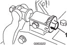
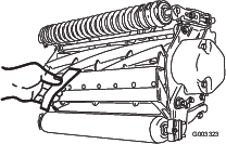
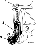
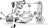
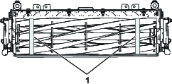
Whenever the cutting unit has to be tipped to expose the bedknife/reel, prop up the rear of the cutting unit with the kickstand (supplied with the traction unit) to make sure that the nuts on the back end of the bedbar adjusting screws are not resting on the work surface (Figure 24).

g191340

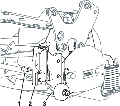
Lubricating the Cutting Units

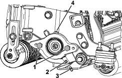
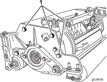
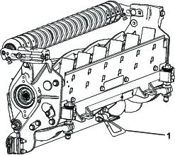
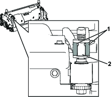
Regularly lubricate the 5 grease fittings of each cutting unit (Figure 25) with No. 2 lithium grease.

There are 2 lubrication points on the front roller, 2 on the rear roller, and 1 at the reel-motor spline.

Note: Model 03192 does not have a front roller; there are only the 2 lubrication points on the rear roller and 1 at the reel-motor spline.

Important: Lubricating the cutting units immediately after washing helps purge water out of the bearings and increases bearing life.

  1. Wipe each grease fitting with a clean rag.

  2. Apply grease until clean grease comes out of the roller seals and the bearing relief valve.

  3. Wipe any excess grease away.

    g191601

Bedknife Specifications

Servicing the Bedknife

Removing the Bedbar/Bedknife Assembly

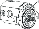
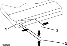
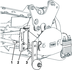
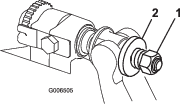
  1. Turn the bedbar-adjuster screws counterclockwise to back the bedknife away from the reel (Figure 26).

    g016647
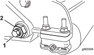
  2. Back out the spring-tension nut until the washer is no longer tensioned against the bedbar (Figure 26).

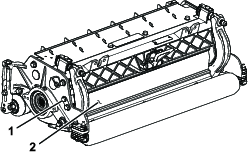
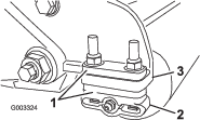
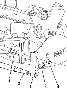
  3. On each side of the machine, loosen the locknut securing the bedbar bolt (Figure 27).

    g003334
  4. Remove each bedbar bolt, allowing the bedbar to be pulled downward and removed from the cutting unit (Figure 27).

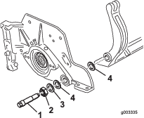
    Account for 2 nylon washers and 1 steel washer on each end of the bedbar (Figure 28).

    g003335
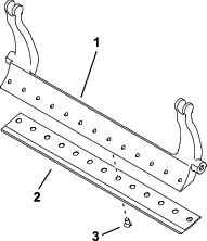
  5. Remove the bedknife from the bedbar by removing all screws holding it in place. Use a socket wrench with the Bedknife Screw Tool (Part No. TOR510880).

    Note: You may use a mechanical or pneumatic impact wrench to loosen the bedknife screws.

    Note: Discard the bedknife and screws.

Installing the New Bedknife

  1. Select a new bedknife per the Bedknife Selection Chart.

  2. Remove the rust, scale, and corrosion from the bedbar surface and apply a thin layer of oil to the bedbar surface.

    Important: Do not remove casting material from the bedbar. The bedbar is concave in the middle by design; do not grind.

  3. Clean the threads in the bedbar.

  4. Apply anti-seize compound on the new bedknife screws and install the bedknife on the bedbar.

    Important: Only use new bedknife screws.

    Note: The quantity of screws varies depending on the bedbar.

    g557599
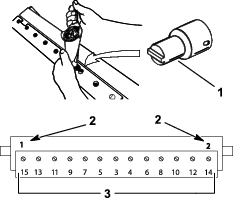
  5. Torque the 2 outer screws to 1 N∙m (10 in-lb).

  6. Working from the center of the bedknife, torque the screws to 29.8 +/- 1 N∙m (22 +/- 1 ft-lb).

    Important: Do not tighten the bedknife screws using a mechanical or pneumatic impact wrench.

    g255046
  7. Grind the new bedknife; refer to Bedknife Service Chart.

Bedknife Service Chart

The bedknife service limits are listed in the following chart.

Important: Operating the cutting unit with the bedknife below the service limit may result in poor after-cut appearance and reduce the structural integrity of the bedknife for impacts.

Bedknife Service Chart
BedknifePart No.Bedknife Lip Height Service Limit*Top/Front Grind Angles
Low HOC147-1248 (27 inch)5.6 mm (0.220 inch)4.8 mm (0.190 inch)10/5°
147-1252 (32 inch)
EdgeMax®137-6095 (27 inch)6.9 mm (0.270 inch)4.8 mm (0.190 inch)10/5°
 
Standard147-1249 (Model 03189/90, 27 inch)6.9 mm (0.270 inch)4.8 mm (0.190 inch)10/5°
147-1253 (Model 03191, 32 inch)
Heavy Duty147-1250 (Model 03192, 27 inch)9.3 mm (0.370 inch)4.8 mm (0.190 inch)10/5°
147-1254 (32 inch)
g027268

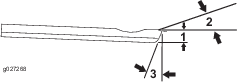
Note: All bedknife service limit measurements relate to the bottom of the bedknife (Figure 32).

g007165

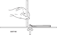
Checking the Top Grind Angle

The angle that you use to grind your bedknives is very important.

Use the angle indicator (Toro Part No. 131-6828) and the angle-indicator mount (Toro Part No. 131-6829) to check the angle that your grinder produces and then correct for any grinder inaccuracy.

  1. Place the angle indicator on the bottom side of the bedknife as shown in Figure 33.

    g034113
  2. Press the Alt Zero button on the angle indicator.

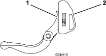
  3. Place the angle-indicator mount on the edge of the bedknife so that the edge of the magnet is mated with the edge of the bedknife (Figure 34).

    Note: The digital display should be visible from the same side during this step as it was in step 1.

    g034114
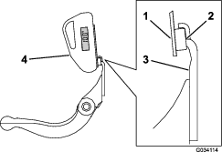
  4. Place the angle indicator on the mount as shown in Figure 34.

    Note: This is the angle that your grinder produces, and should be within 2° of the recommended top grind angle.

Installing the Bedbar/Bedknife Assembly

  1. Install the bedbar/bedknife assembly, positioning the mounting ears between the washer and the bedbar-adjusting screw.

    Important: Center the DPA adjusters in the bedbar ears as shown in Figure 35.If DPA adjusters are installed against the bedbar ears, this may negatively affect the bedknife-to-reel contact.

    g512172
  2. Secure the bedbar to each side plate with the bedbar bolts (nuts on bolts) and 3 washers (6 total).

  3. Position a nylon washer on each side of the side-plate boss. Place a steel washer outside each of the nylon washers (Figure 28).

  4. Torque the bedbar bolts to 37 to 45 N∙m (27 to 33 ft-lb).

  5. Slowly tighten the bedbar locknuts until the outer steel washers just rotate by hand.

    Important: Do not overtighten the locknuts or they will deflect the side plates.

    Note: The nylon washer between the bedbar and slide plate will have a small gap.

  6. Tighten the spring-tension nut until the spring is collapsed, then back it off 1/2 turn (Figure 36).

    g006505

Reel Specifications

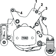
Installing the Front Shaft Assembly for Reel Grinding

Important: You must order the following parts so that the cutting unit can be fitted to a reel grinding machine:

Qty.PartPart No.
2Front HOC bracket125-2796
2Carriage bolt (3/8 x 1-1/2 inches)3231-4
2Locknut (3/8 inch)104-8301
2Hex-head bolt (5/16 x 1-1/8 inches)322-16
1Front roller shaft117-0957
  1. Remove the shop roller assemblies (if equipped); refer to Adjusting the Shop Roller Assemblies (Model 03192 Only).

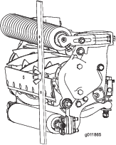
  2. Using the carriage bolts and locknuts, install front HoC brackets to the top hole of the side plate (Figure 37).

    Important: Ensure that the HOC bracket is installed with the carriage bolt at the top of the slot, so that the HOC bracket is as low as possible.

    g361153
  3. Install the shaft to the bottom of the HOC brackets using the 2 hex-head bolts.

  4. Ensure that the shaft is parallel to the cutting unit; if it is not, loosen the carriage bolt on the low side and tighten it again when the shaft is parallel.

Relief-Grinding the Reel

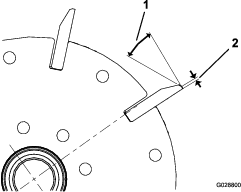
The new reel has a land width of 1.3 to 1.5 mm (0.050 to 0.060 inch) and a 30° relief grind.

When the land width gets larger than 3 mm (0.120 inch) wide, do the following:

  1. Apply a 30° relief grind on all reel blades until the land width is 1.3 mm (0.050 inch) wide (Figure 38).

    g028800
  2. Spin grind the reel to achieve <0.025 mm (0.001 inch) reel run-out.

    Note: This causes the land width to grow slightly.

    Note: To extend the longevity of the sharpness of the edge of the reel and the bedknife—after grinding the reel and/or the bedknife—check the reel to bedknife contact again after cutting 2 fairways, as any burrs will be removed, which may create improper reel to bedknife clearance and thus accelerate wear.

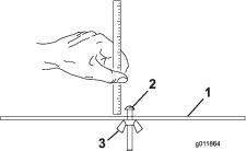
  3. Using diameter measuring tape, measure the outside diameter of the reel at both ends (Figure 39); the difference in outside diameter between the ends should be less than 0.010 inches (0.250 mm). If the difference is greater, grind to correct the difference.

    Note: Outside diameter measuring tape is available from your authorized Toro distributor.

    g342519

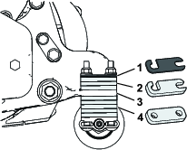
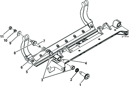
Servicing the HD Dual Point Adjusters (DPA)

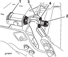
  1. Remove all parts (refer to the Installation Instructions for the HD DPA Kit and to Figure 40).

  2. Apply anti-seize compound to the inside of the bushing area on cutting unit center frame (Figure 40).

  3. Align the keys on flange bushings to the slots in the frame and install the bushings (Figure 40).

  4. Install a wave washer onto the adjuster shaft and slide the adjuster shaft into the flange bushings in the frame of the cutting unit (Figure 40).

  5. Secure the adjuster shaft with a flat washer and locknut (Figure 40).

  6. Torque the locknut to 20 to 27 N∙m (15 to 20 ft-lb).

    Note: The bedbar adjuster shaft has left-hand threads.

    g016926
  7. Apply anti-seize compound to the threads of the bedbar-adjuster screw that fit into the adjuster shaft.

  8. Thread the bedbar-adjuster screw into the adjuster shaft.

  9. Loosely install the hardened washer, spring, and spring tension nut onto the adjuster screw.

  10. Install the bedbar, positioning the mounting ears between the washer and the bedbar adjuster.

  11. Secure the bedbar to each side plate with the bedbar bolts (nuts on bolts) and 6 washers.

    Note: Position a nylon washer on each side of the side-plate boss.

  12. Place a steel washer outside each of the nylon washers (Figure 40).

  13. Torque the bedbar bolts to 37 to 45 N∙m (27 to 33 ft-lb).

  14. Tighten the locknuts until the outside steel washer stops rotating and end play is removed but do not overtighten or deflect the side plates.

    Note: The washers on the inside may have a gap (Figure 40).

  15. Tighten the nut on each bedbar-adjuster assembly until the compression spring is fully compressed, then loosen the nut 1/2 turn (Figure 40).

  16. Repeat this procedure on the other end of the cutting unit.

  17. Adjust the bedknife to the reel; refer to Adjusting the Bedknife to the Reel.

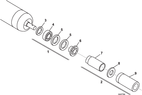
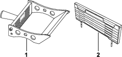
Servicing the Roller

The Roller Rebuild Kit (Part No. 114-5430) and the Roller Rebuild Tool Kit (Part No. 115-0803) (Figure 41) are available for servicing the roller. The Roller Rebuild Kit includes all the bearings, bearing nuts, inner seals, and outer seals to rebuild a roller. The Roller Rebuild Tool Kit includes all the tools and the installation instructions required to rebuild a roller with the roller rebuild kit. Refer to your parts catalog or contact your authorized Toro distributor for assistance.

g007790