Important: For 2015 and older machines, discard the springs included in this kit and order 2 springs (Toro Part No. 117-4847) from your authorized Toro distributor. For 2016 and newer machines, use the heavy-duty springs supplied in this kit.The springs should be installed only by qualified Toro Service Technicians using approved tools.
Warning
Improper removal, disassembly, or installation of the spring assembly poses a danger to you and bystanders.
Contact your authorized Toro distributor to install this kit.
Important: For electric machines, install the 12V Fuse Kit (Toro Part No. 161-2008, sold separately) prior to installing the cab.
Safety
Safety and Instructional Decals
 |
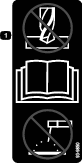
Safety decals and instructions are easily visible to the operator and are located near any area of potential danger. Replace any decal that is damaged or missing. |


Installation
Preparing the Machine
-
Park the machine on a level surface.
-
Engage the parking brake.
-
Raise the bed until the bed prop rod is fully engaged; refer to your Operator’s Manual.
-
Shut off the machine and remove the key.
-
Disconnect the battery; refer to the Operator’s Manual for the machine.
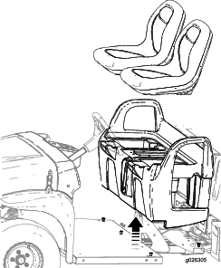
Removing the Seat Base
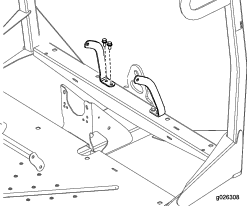
Remove the 8 bolts securing the seat base to the floor plate and front frame and lift the seats and seat base from the machine (Figure 1).
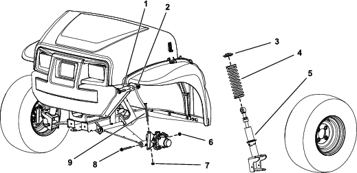
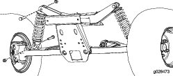
Removing the Strut Assembly (for 2016 and Newer Machines Only)
-
Raise the front of the machine off the ground and support it with jack stands.
-
Remove the front wheel.
-
Remove the hex-head bolt (3/8 x 4-3/4 inches) and flange nut (3/8 inch) from the spindle (Figure 2).
-
Remove the hex-head bolt (3/8 x 3-1/2 inches) and flange nut (3/8 inch) from the control arm (Figure 2).
-
Remove the hex-head bolt (1/2 x 2-1/4 inches) and locknut (1/2 inch) securing the strut assembly to the upper frame (Figure 2).
-
Remove the strut assembly (Figure 2).
Note: Repeat this procedure for the other side of the machine.
Installing the Springs (for 2016 and Newer Machines Only)
Parts needed for this procedure:
| Spring | 2 |
Use an approved Toro spring-compression tool to remove and install springs of the strut assembly. Contact your authorized Toro distributor.
-
Place the strut assembly into the compression tool and use the tool to compress the spring.
-
While the spring is compressed, remove the collar.
-
Remove the spring from the strut assembly (Figure 2).
-
Install the new spring over the existing strut assembly (Figure 2).
-
Using the Toro spring-compression tool, compress the spring.
-
While the spring is compressed, install the collar.
-
Carefully release pressure on the spring, allowing it to seat on the collar.
-
Remove the strut assembly from the compression tool.
Note: Repeat this procedure for the other side of the machine.
Installing the Strut Assembly (for 2016 and Newer Machines Only)
-
Install strut assembly to the machine.
-
Secure the upper portion of the strut assembly to the frame using the upper, hex-head bolt (1/2 x 2-1/4 inches) and locknut (1/2 inch) as shown in Figure 2.
-
Torque the hex-head bolt (1/2 x 2-1/4 inches) to 91 to 113 N∙m (67 to 83 ft-lb).
-
Install the hex-head bolt (3/8 x 4-3/4 inches) and flange nut (3/8 inch) to the spindle (Figure 2).
-
Torque the hex-head bolt (3/8 x 4-3/4 inches) to 37 to 45 N∙m (27 to 33 ft-lb).
-
Secure the lower portion of the strut assembly to the control arm using the hex-head bolt (3/8 x 3-1/2 inches) and flange nut (3/8 inch) as shown in Figure 2.
-
Torque the hex-head bolt (3/8 x 3-1/2 inches) to 37 to 45 N∙m (27 to 33 ft-lb).
-
Install the front wheel.
Note: Repeat this procedure for the other side of the machine.
Installing the Compression Spring (for 2015 and Older Machines Only)
Parts needed for this procedure:
| Compression spring | 2 |
Use an approved Toro spring-compression tool to remove and install springs of the strut assembly. Contact your authorized Toro distributor.
Important: For 2015 and older machines, discard the springs included in this kit and order 2 springs (Toro Part No. 117-4847) from your authorized Toro distributor.
-
Raise the front of the machine off the ground and support it with jack stands.
-
Remove the current shock assemblies as shown in Figure 3.
-
Using a spring compressor, remove the current springs and install the springs from this kit.
-
Install the shock assemblies and turn them 3 clicks up from the longest position.
Note: Refer to the Service Manual for further instructions on replacing the spring and checking the front end toe of the tires.
-
Torque the bolts to 95 to 122 N∙m (70 to 90 ft-lb).
Installing the Floor Mounts
Parts needed for this procedure:
| Floor mount | 2 |
| Nut (3/8 inch) | 6 |
| Bolt (3/8 x 1 inch) | 4 |
| Bolt (5/16 inch) | 2 |
| Nut (5/16 inch) | 2 |
| Bolt (3/8 x 7/8 inch) | 2 |
| Washer | 2 |
-
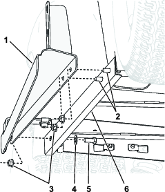
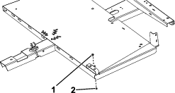
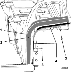
Secure the floor mounts to the side of the frame as shown in Figure 4.
-
Secure the floor mounts to the top of the frame as shown in Figure 5.
-
Torque the 2 bolts (3/8 x 7/8 inch) and 4 bolts (3/8 x 1 inch) to 37 to 45 N∙m (27 to 33 ft-lb).
-
Torque the 2 bolts (5/16 inch) to 1978 to 2543 N∙cm (175 to 225 in-lb).
Installing the Cab Frame
Parts needed for this procedure:
| Cab frame | 1 |
| Bolts (3/8 x 7/8 inch) | 4 |
| Bolt (3/8 x 3/4 inch) | 10 |
| Nuts (3/8 inch) | 10 |
-
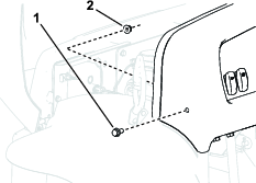
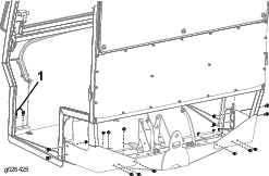
If your machine is equipped with hardware securing the dash on the sides of the machine, raise the hood and remove the bolt and locknut (Figure 6).
Note: Retain the removed hardware for later installation.
-
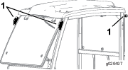
Lift the cab frame using the lifting points and place it on the machine (Figure 7).
-
Secure the frame to the machine using 10 bolts (3/8 x 3/4 inch), 10 nuts (3/8 inch), and 4 bolts (3/8 x 7/8 inch) as shown in Figure 8.
-
Torque the bolts to 37 to 45 N∙m (27 to 33 ft-lb).
Installing the Side Panels
Parts needed for this procedure:
| Side-plate panels | 2 |
| Bolts (1/4 inch) | 4 |
| Side-plate foam panel | 2 |
Installing the Seat Belts
Parts needed for this procedure:
| Seat-belt anchor | 2 |
| Bolts (3/8 x 3/4 inch) | 4 |
| Nuts (3/8 inch) | 4 |
| Seat-belt receiver end | 2 |
| Bolt (7/16 inch) | 4 |
| Nut (7/16 inch) | 4 |
| Seat-belt bracket | 2 |
| Seat belt | 2 |
| Bolt (3/8 x 7/8 inch) | 2 |
-
Mount a seat-belt bracket to each ROPS tab with 2 bolts (3/8 inch) as shown in Figure 10.
-
Torque the 4 bolts (3/8 inch) to 37 to 45 N∙m (27 to 33 ft-lb).
-
Mount the retractable end of each seat-belt assembly to each seat-belt anchor bracket with a bolt (7/16 inch) and a nut (7/16 inch) as shown in Figure 10.
-
Torque the 2 bolts (7/16 inch) to 67 to 83 N∙m (49 to 61 ft-lb).
-
Secure the left and right seat-belt anchor to the front frame with 4 bolts (3/8 x 3/4 inch) and 4 nuts (3/8 inch) as shown in Figure 11.
-
Torque the 4 bolts (3/8 x 3/4 inch) to 37 to 45 N∙m (27 to 33 ft-lb).
-
Drill a hole in each of the dimples on the top of the seat shroud as shown in Figure 12.
Important: Use caution when drilling these holes; electrical components and control cables are located under the seat shroud.
Warning
Using a drill without proper eye protection may allow debris to enter the eye, causing injury.
When drilling, always wear eye protection.

-
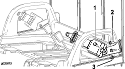
Insert the mounting side of the receiver end of each seat-belt lock assembly into one of the newly drilled holes in the seat base (Figure 13).
-
Mount the receiver end of each seat-belt assembly to each seat-belt anchor with a bolt (7/16 inch) and nut (7/16 inch) as shown in Figure 13.
-
Torque the bolts to 67 to 83 N∙m (49 to 61 ft-lb).
-
Install the seat base; reverse the steps in Removing the Seat Base.
Routing the Wire Harness
Parts needed for this procedure:
| Wire harness | 1 |
| Clip tie | 1 |
| Plug | 1 |
| Fuse—30 A (gasoline machines only) | 1 |
| Fuse—25 A (electric machines only) | 1 |
-
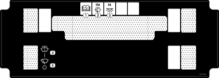
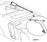
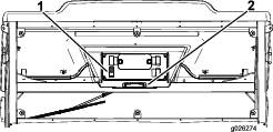
Route the wire harness under the control panel; install the clip tie in the lower hole on the side panel and the plug in the top hole (Figure 14).
-
For Workman MDX/MDXD machines:
-
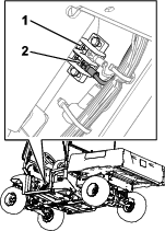
Connect the ring terminal on the harness to the grounding block on the center dash support (Figure 15).
Note: If there is not an available fuse-block connection, you need to add a fuse block to the fuse-block grouping. Contact your authorized Toro distributor for more information.
-
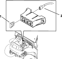
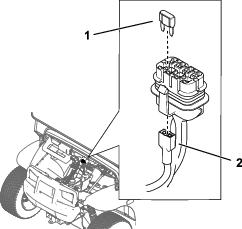
Insert the fuse-block connector and fuse into an available fuse-block connection (Figure 16 or Figure 17).
-
-
Connect the battery and lower the bed; refer to the Operator’s Manual.
Product Overview
Control Panel
Windshield-Wiper Switch
Push the top of the switch to activate the windshield wipers (Figure 18).
Note: If you have the optional windshield washer fluid kit (sold separately), momentarily push in the upper half of the wiper/washer switch to spray the washer fluid onto the windshield.
Light Switch
Push the light plate to turn on the light (Figure 18).