Introduction
Read this information carefully to learn how to operate and maintain your product properly and to avoid injury and product damage. You are responsible for operating the product properly and safely.
Visit www.Toro.com for product safety and operation training materials, accessory information, help finding a dealer, or to register your product.
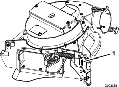
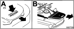
Whenever you need service, genuine Toro parts, or additional information, contact an Authorized Service Dealer or Toro Customer Service and have the model and serial numbers of your product ready. Figure 1 identifies the location of the model and serial numbers on the product. Write the numbers in the space provided.
This manual identifies potential hazards and has safety messages identified by the safety alert symbol (Figure 2), which signals a hazard that may cause serious injury or death if you do not follow the recommended precautions.

This manual uses 2 words to highlight information. Important calls attention to special mechanical information and Note emphasizes general information worthy of special attention.
Warning
CALIFORNIA
Proposition 65 Warning
Use of this product may cause exposure to chemicals known to the State of California to cause cancer, birth defects, or other reproductive harm.
Safety
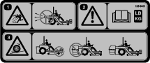
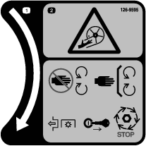
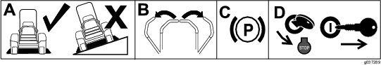
Safety and Instructional Decals
 |
Safety decals and instructions are easily visible to the operator and are located near any area of potential danger. Replace any decal that is damaged or lost. |


Installation
Important: Do not use drive or caster Tweels with this attachment. If the machine is equipped with drive or caster Tweels, replace them with factory pneumatic drive tires or factory pneumatic or semi-pneumatic caster tires.
Note: Determine the left and right sides of the machine from the normal operating position.
Preparing the Machine
-
Park the machine on a level surface.
-
Move the motion-control levers to the NEUTRAL-LOCK position.
-
Engage the parking brake.
-
Shut off the engine and remove the key.
Removing the Existing Belt Cover, Belt, and Bracket
Note: Clean the area around the belt cover before removing.
-
Lower the mower deck to the lowest height-of-cut position.
-
Remove the right belt cover (Figure 4).
-
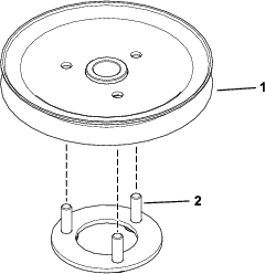
For 48-inch and 52-inch mowers only: Loosen the bolts holding the right spindle to the mower deck (Figure 5).
Note: This will allow access to the nuts holding the right belt cover bracket to the mower deck.
-
Remove the existing right belt cover bracket (Figure 5 and Figure 6).
-
Store the right belt cover, bracket, and hardware for later use if you remove the bagger blower and pulley.
-
Remove and retain the deck belt.
Installing the Pulley Assembly and Belt
Parts needed for this procedure:
| Pulley assembly | 1 |
| Pulley-plate mount—for machines with an aluminum spindle only | 1 |
| Flange nut (3/8 inch)—for machines with an aluminum spindle only | 3 |
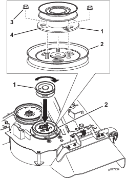
For Machines with an Aluminum Spindle
-
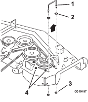
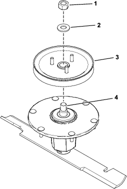
Remove the top nut, washer, and sheave from the spindle (Figure 7).
Note: Note the orientation of the sheave when you remove it from the spindle to ensure that you install it properly later in the process.
-
Insert the pulley-plate mount studs into the holes in the sheave (Figure 8).
-
Install the sheave assembly to the spindle using the washer and top nut (Figure 9).
-
Torque the top nut to 176 to 217 N∙m (130 to 160 ft-lb).
Note: Ensure that the sheave spins freely.
-
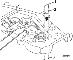
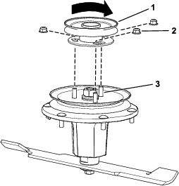
Align the new pulley assembly so that the openings fit over the studs (Figure 10).
-
Turn the pulley to lock it into position (Figure 10).
-
After the new pulley assembly is in position, install the nuts to secure the new pulley assembly (Figure 10).
Torque the 3 nuts to 28 to 34 N∙m (21 to 25 ft-lb).
-
Install the deck belt.
For Machines with Bolts
-
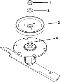
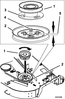
Loosen, but do not remove, the tapping bolts on the existing mower-deck pulley (Figure 11).
Note: There should be a 5 mm (3/16 inch) clearance between the bolt head and pulley.
-
Align the new pulley assembly so that the openings fit over the pulley bolt heads (Figure 11).
-
Turn the pulley to lock it into position (Figure 11).
Note: If the pulley does not turn, loosen the bolts more to raise the bolt heads and allow the pulley to lock into position.
-
After the new pulley assembly is in position, tighten the existing bolts to secure new pulley assembly.
Note: Torque the bolts to 28 to 34 N∙m (21 to 25 ft-lb).
-
Install the deck belt.
For Machines without Bolts
-
Remove the nuts on the existing mower-deck pulley (Figure 12).
-
Install the new pulley assembly onto the mower-deck pulley bolts (Figure 12).
-
Turn the pulley to lock it into position (Figure 12).
-
After the new pulley assembly is in position, install the nuts to secure new pulley assembly.
Note: Torque the nuts to 28 to 34 N∙m (21 to 25 ft-lb).
-
Install the deck belt.
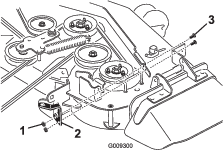
Installing the New Belt Cover Bracket
Parts needed for this procedure:
| Belt cover bracket | 1 |
| Carriage bolt (1/4 x 3/4 inches) | 2 |
| Locknut (1/4 inch) | 2 |
Install the belt cover bracket with 2 carriage bolts (1/4 x 3/4 inches) and 2 locknuts (1/4 inch) as shown in Figure 13.
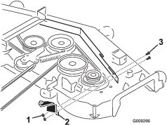
Installing the New Belt Cover Bracket
Parts needed for this procedure:
| Belt cover bracket | 1 |
| Carriage bolt (1/4 x 3/4 inches) | 2 |
| Locknut (1/4 inch) | 2 |
Install the belt cover bracket with 2 carriage bolts (1/4 x 3/4 inches) and 2 locknuts (1/4 inch) as shown in Figure 14.
Installing the Blower Assembly, Bagger Belt, Spring and Blower-Belt Cover
Parts needed for this procedure:
| Blower assembly | 1 |
| Bagger belt | 1 |
| Blower belt cover | 1 |
| Spring | 1 |
Refer to the bagger Operator's Manual for the correct procedure to install the blower, bagger belt, spring, and blower-belt cover.