Disclaimers and Regulatory Information
 |
| |
| CALIFORNIA |
| |
| Proposition 65 |
| |
| The power cord on this product
contains lead, a chemical known to
the State of California to cause birth defects or
other reproductive
harm. Wash hands after handling. |
| |
| Battery posts, terminals, and
related accessories contain lead and
lead compounds, chemicals known to the State of
California to cause
cancer and reproductive harm. Wash hands after handling. |
| |
| Use of this product may cause
exposure to chemicals known to the
State of California to cause cancer, birth defects,
or other reproductive
harm. |
| |
FCC
This device
complies with Part 15 of the FCC Rules. Operation is subject to the
following conditions: (1) this device may
not cause harmful interference, and (2) this device must accept any
interference received, including interference that may
cause undesired operation. Changes or modifications not
expressly approved by Toro could void the user’s authority to operate the equipment.
In
addition, while in charging mode this equipment has been tested and
found to comply with the limits for a Class B digital
device, pursuant to Part 15 of the FCC rules. These limits
are designed to provide reasonable protection against harmful interference
in a residential installation. This equipment
generates, uses and can radiate radio frequency energy and, if not
installed and used in accordance with the
instructions, may cause harmful interference to radio communications.
However, there is no guarantee that interference
will not occur in a particular installation. If this equipment does
cause harmful interference to radio or television
reception, which can be determined by turning the equipment off and
on, the user is encouraged to try to correct
the interference by one or more of the following measures:
- Reorient or relocate the receiving
antenna.
- Increase the separation between
the equipment and receiver.
- Connect equipment into an outlet
on a circuit different from that to which the receiver is connected.
- Consult the dealer or an experienced
radio/TV technician for help.
Maintenance
Recommended Maintenance Schedule
| After the first 50 hours
|
|
| Before each use or daily |
|
| |
| |
| Check for loose fasteners.
|
| Every 40 hours
|
|
| Every 50 hours
|
|
| Every 500 hours |
|
| |
| |
| |
| |
| Every 1,500 hours
|
Replace all moving hydraulic hoses.
|
| Yearly or before storage |
Touch up chipped paint. |
| |
| |
| |
| |
| |
Pre-Maintenance Procedures
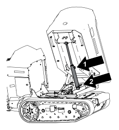
Lowering the Hopper without Power
Model: 68140
-
Install the
cylinder lock.
-
Ensure that
the hopper is empty.
-
Remove the
bottom cover and place a large drain pan under the dump cylinder.
-
Loosen the
fitting on the rod end of the cylinder  to allow air to flow in.
-
Disconnect
the fitting on the base end of the cylinder  and allow the fluid to drain.
Note: Dispose of the used fluid at a certified recycling center.
-
Use a hoist
or have 2 people hold up the hopper and remove and store the cylinder
lock.
-
Carefully
lower the hopper.
-
After making
repairs, raise the hopper, install the cylinder lock.
-
After lubricating
the fitting seal with clean hydraulic fluid, re-torque both hoses
to 18-20 ft-lbs (24 to 27
N·m) while
using a backup wrench on the hose fitting to eliminate twist.
-
Add hydraulic
fluid.
-
Remove the
cylinder lock
-
Retract the
cylinder through the entire stroke while avoiding running over relief
at the end of stroke.
-
Fully extend
the cylinder through the entire stroke while avoiding running over
relief at the end of stroke.
-
Check that
the hydraulic fluid level is adequate and add/remove fluid as necessary.
-
Repeat steps
12 and 13 for three additional cycles
-
Repeat step
14.
Lowering the Hopper Platform without
Power
Model: 68142
-
Pull and
hold the manual override knob until the hopper fully lowers.
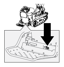
Lowering the Hopper without Power
Model: 68142
-
Install the
cylinder lock.
-
Ensure that
the hopper is empty.
-
Use a hoist
hold up the hopper and remove and store the cylinder lock.
-
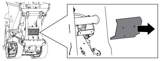
Remove the
guard and place a large drain pan under the hydraulic fittings.
-
Loosen the
fitting on the rod end of the cylinder to allow air to flow in.
-
Disconnect
the fitting on the base end of the cylinder and allow the fluid to drain.
Note: Dispose of the used fluid at a certified recycling center.
-
Slowly lower
the hopper using the hoist.
-
After making
repairs, raise the hopper and install the cylinder lock.
-
After lubricating
the fitting seal with clean hydraulic fluid, re-torque both hoses
to 30-33 ft-lbs (41 to 45
N·m).
-
Retract the
dump cylinder through the entire stroke while avoiding running over
relief at the end of stroke.
-
To access
the hydraulic reservoir, fully extend hopper lift cylinder to end
of stroke while avoiding running over relief at
the end of stroke.
-
Check that
the hydraulic fluid level is adequate and add/remove fluid as necessary.
-
Fully extend
the dump cylinder to end of stroke while avoiding running over relief
at the end of stroke.
-
Check that
the hydraulic fluid level is adequate and add/remove fluid as necessary.
-
Retract the
cylinder through the entire stroke while avoiding running over relief
at the end of stroke.
-
Fully extend
the cylinder through the entire stroke while avoiding running over
relief at the end of stroke.
-
Repeat steps
15 and 16 for three additional cycles.
-
Check that
the hydraulic fluid level is adequate and add/remove fluid as necessary.
Raising the Hopper without Power
-
Remove any
material from the hopper.
-
Raise the
machine and support it using jack stands rated for the weight of the
machine.
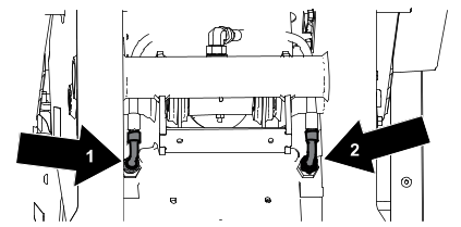
-
Place a large
drain pan under the manual lower valve.
-
Loosen C1
and C2 hose fittings.
-
Attach the
proper lifting mechanism to the hopper and lift the high lift platform
until the safety lockout can be installed.
-
Install the
safety lockout.
-
After making
repairs, lubricate the C1 and C2 fitting seals using clean hydraulic
fluid and re-torque both hoses to 30-33 ft-lbs (41 to 45 N·m) while using a backup
wrench on the hose fitting to eliminate twist.
-
Lower the
hopper platform halfway, then extend fully while avoiding running
over relief at the end of stroke.
-
Install the
safety lockout.
-
Check that
the hydraulic fluid level is adequate and add/remove fluid as necessary.
-
Lower the
hopper platform fully while avoiding running over relief at the end
of stroke.
-
Raise the
hopper platform fully while avoiding running over relief at the end
of stroke.
-
Check that
the hydraulic fluid level is adequate and add/remove fluid as necessary.
-
Repeat steps
11 and 12 for three additional cycles.
-
Extend the
hopper dump cylinder fully.
-
Check that
the hydraulic fluid level is adequate and add/remove fluid as necessary.
Retrieving the Machine
Under normal
conditions, do not tow the machine. If the machine becomes disabled
and retrieval is needed:
- Do not tow the machine for more
than 180 m (200 yd).
- Tow the machine at less than 1.5
to 3.0 km/h (1 to 2 mph).
- You cannot steer the machine as
it is towed.
- Use a maximum towing force of
1.5 times the machine weight.
-
Drive the
towing vehicle to the front of the machine.
-
Attach the
machine to the towing vehicle using the tie-down points.
-
Ensure that
all controls are in Neutral.
-
After towing:
-
Move the
controls to Neutral.
-
Disconnect
the machine from the towing vehicle.
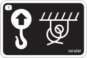
Lifting the Machine
Ensure that the hopper is empty
before lifting the machine.
-
Place the
platform in the raised position.
-
Ensure that
the hopper is in the lowered position.
-
Hoist the
machine using the 4 lifting points.
Note: Take up the slack in the chain or straps to properly balance the
unit.
Using the Safety Lock
-
Park the
machine on a level surface, ensure that the control levers are in
the Neutral position,
fully raise the hopper, and turn off the machine.
-
Rotate the
safety lock until it hooks onto the machine.
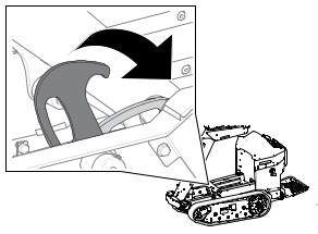
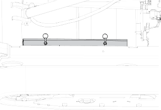
Using the Cylinder Lock
Installing the Cylinder Lock
-
Park the
machine on a level surface, ensure that the control levers are in
the Neutral position,
fully raise the hopper, and turn off the machine.
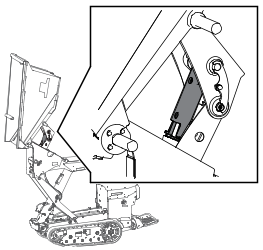
-
Remove the
2 cotterless pins securing the cylinder lock to the machine.
-
Slide the
cylinder lock over the lift-cylinder rod and secure with the cotterless
pins.
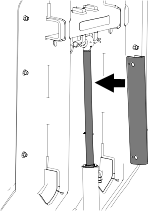
Removing and Storing the Cylinder Lock
Remove the cylinder lock from
the lift-cylinder rod and fully secure it in the storage position
before operating the machine.
-
Start the
machine.
-
Fully raise
the hopper.
-
Remove the
cotterless pins securing the cylinder lock.
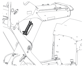
-
Place the
cylinder lock on the posts inside the machine frame and secure with
the cotterless pins.
-
Lower the
hopper.
-
Shut off
the machine.
Lubrication
Greasing the Machine
Model: 68140
Grease Type: General-purpose grease.
Note: Remove the blue protection caps, if applicable, before greasing and
replace when finished.
-
Park the
machine on a level surface.
-
Shut off
the machine.
-
Clean the
grease fittings with a rag.
-
Connect a
grease gun to each fitting.
-
Pump grease
into the fittings until grease begins to ooze out of the fittings
(approximately 3 pumps).
-
Wipe up any
excess grease.
Greasing the Machine
Model: 68142
Grease Type: General-purpose grease.
Note: Remove the blue protection caps, if applicable, before greasing and
replace when finished.
-
Park the
machine on a level surface.
-
Shut off
the machine.
-
Clean the
grease fittings with a rag.
-
Connect a
grease gun to each fitting.
-
Pump grease
into the fittings until grease begins to ooze out of the fittings
(approximately 3 pumps).
-
Wipe up any
excess grease.
Electrical System Maintenance
Electrical System Safety
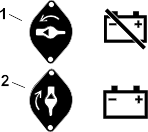
- Disconnect the battery before
repairing the machine. Disconnect the negative terminal first and
the positive last. Connect the positive
terminal first and the negative last.
- Charge the battery in an open,
well-ventilated area, away from sparks and flames. Unplug the charger
before connecting or disconnecting the
battery. Wear protective clothing and use insulated tools.
- Battery acid is poisonous and
can cause burns. Avoid contact with skin, eyes, and clothing. Protect
your face, eyes, and clothing when working
with a battery.
- Battery gases can explode. Keep
cigarettes, sparks, and flames away from the battery.
Battery Service
Note: The machine is equipped with 6 lithium-ion batteries.
Dispose of or recycle lithium-ion
batteries in accordance with local and federal regulations. If a battery
requires service, contact your Authorized
Service Dealer for assistance.
The only user serviceable parts
on a battery are the labels. If you are having problems with a battery,
contact your Authorized Service Dealer for
assistance.
Battery Maintenance
 |
Warning |
|
The batteries contain high voltage,
which could burn or shock you.
- Do not attempt to open the batteries.
- Use extreme care when handling
a battery with a cracked case.
- Use only the charger designed
for the batteries.
The
lithium-ion batteries hold a sufficient charge to perform intended
work during its life span.
To achieve maximum life and use
from your batteries, follow these guidelines:
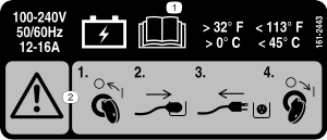
Charging the Batteries
|
Danger |
|
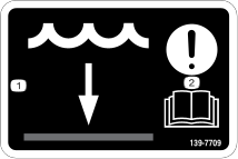
Contact with water while charging
the machine could cause electric shock, causing injury or death.
- Do not handle the plug with wet
hands or while standing in water.
- Do not charge the batteries in
the rain or in wet conditions.
|
Warning |
|
A damaged charger cord can cause
an electrical shock or a fire.
Thoroughly inspect the charger
cord before charging the machine. If the cord is damaged, do not charge
the machine until you obtain a replacement.
To
reduce the risk of electric shock, this charger has a 3-prong grounded
plug (type B). If the plug does not fit into the
wall receptacle, other grounded plug types are available;
contact an Authorized Service Dealer.
Do not change the charger
plug in any way.
Check the charger cord periodically
for holes or cracks in the insulation. Do not use a damaged cord.
Do not run the cord through standing
water or wet grass.
Recommended temperature
range for charging: 0° to 45°C (32° to 113°F).
Charge the batteries only in temperatures
that are within the recommended range.
Note: The charger will not function in temperatures exceeding the minimum
or maximum temperatures.
-
Park the
machine in the designated location for charging.
-
Shut off
the machine and remove the key.
-
Ensure that
the electrical service disconnect switch is in the On position.
-
Plug the
charger cord into the machine.
-
Plug the
other end of the charger cord into a grounded electrical outlet.
-
Observe the
display to ensure that the batteries are charging.
Note: The display shows the battery charge percentage and amperage. Batteries
with a lower voltage charge first; once they reach
the voltage of the other batteries, all batteries
charge simultaneously. The fan may turn on while the machine is charging.
When charging is complete, the
display shuts off.
-
When the
machine reaches a sufficient level, disconnect the charger cord from
the outlet.
-
Store the
charger cord in the storage compartment and close the cover.
-
Start the
machine and verify the charge level using the display.
Charger Maintenance
All electrical repairs should
be performed by an Authorized Service Dealer only.
The charger
requires little maintenance other than protecting it from damage and
weather.
- Clean the charger cord with a
slightly damp cloth after each use.
- Coil the cord when not in use.
- Periodically examine the cord
for damage, and replace it when necessary with Toro-approved parts.
Drive System Maintenance
Track Service
Cleaning the Tracks
-
Park the
machine on a level surface, move the motion-control levers to the Neutral-lock position, engage the parking
brake, and lower the hopper.
-
Shut off
the machine, remove the key, and allow the machine to cool.
-
Lift/support
the side of the machine to be worked on so that the track is 7.6 to
10 cm (3 to 4 inches) off the ground.
-
Using a water
hose or pressure washer, remove dirt from each track system.
Ensure
that you use high-pressure water to wash only the track area. Do not
use a high-pressure washer to clean the rest of
the machine. Do not use high-pressure water between
the drive sprocket and the machine or you may damage the motor seals.
High-pressure washing can damage
the electrical system and hydraulic valves or deplete grease.
Ensure
that you fully clean the road wheels, the front wheel, and the drive
sprocket. The road wheels should rotate freely
when clean.
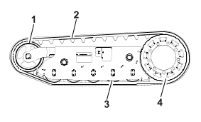
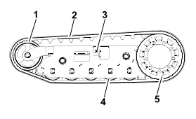
G543780
- Front
wheel
- Track
- Road
wheel
- Drive
sprocket
Adjusting the Track Tension
-
Park the
machine on a level surface, move the motion-control levers to the Neutral-lock position, engage the parking
brake, and lower the hopper.
-
Shut off
the machine, remove the key, and allow the machine to cool.
-
Clean the
tracks with high-pressure water.
Ensure
that you use high-pressure water to wash only the track area. Do not
use a high-pressure washer to clean the rest of
the machine. Do not use high pressure water between
the drive sprocket and the machine or you may damage the motor seals.
High-pressure washing can damage
the electrical system and hydraulic valves or deplete grease.
-
Raise the
machine so that the tracks are off the ground.
-
Clean the
drive sprocket, the front wheel, and the road wheels. The road wheels
should spin freely when clean.
-
Remove the
bolt (1/4 x 1-5/8 inches)  , spacer
  , and nut
  .
.
-
Turn the
tensioning bolt  to adjust the distance
between the tension nut and the end tangent of
the tension tube until the distance is correct.
to adjust the distance
between the tension nut and the end tangent of
the tension tube until the distance is correct.
-
Align the
closest notch in the tensioning bolt to the bolt hole and secure the
tensioning bolt with the bolt (1/4 x 1-5/8
inches), spacer, and nut.
Replacing the Tracks
Removing a Track
-
Park the
machine on a level surface, move the motion-control levers to the Neutral-lock position, engage the parking
brake, and lower the hopper.
-
Shut off
the machine, remove the key, and allow the machine to cool.
-
Lift/support
the side of the machine to be worked on so that the track is 7.6 to
10 cm (3 to 4 inches) off the ground.
-
Remove the
retaining bolt for the tensioning screw.
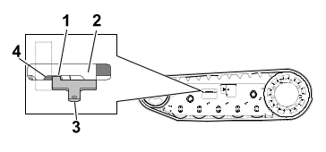
G546676
- Front
wheel
- Track
- Tensioning
screw and retaining bolt
- Road
wheel
- Drive
sprocket
-
Release the
drive tension by turning the tensioning screw clockwise.
-
Remove the
track at the top of the front wheel, peeling it off the wheel while
rotating the track forward.
-
When the
track is off the front wheel, remove it from the drive sprocket and
road wheels.
-
Inspect the
condition of the wheels. If the wheels show signs of wear, replace
them at this time.
Installing a Track
-
Park the
machine on a level surface, move the motion-control levers to the Neutral-lock position, engage the parking
brake, and lower the hopper.
-
Shut off
the machine, remove the key, and allow the machine to cool.
-
Lift/support the side of the machine
to be worked on.
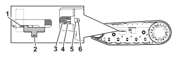
G546676
- Front
wheel
- Track
- Tensioning
screw and retaining bolt
- Road
wheel
- Drive
sprocket
-
Beginning
at the drive sprocket, coil the new track around the sprocket, ensuring
that the lugs on the track fit between the
spacers on the sprocket.
-
Push the
track under the lugs and between the road wheels.
-
Starting
at the bottom of the front wheel, install the track around the wheel
by rotating the track rearward while pushing
the lugs into the wheel.
-
Tension the
track.
-
Lower the machine to the ground.
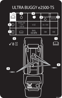
Drive-Motor Gear Oil Specifications
Note: Specifications and design are subject to change without notice.
| Oil Type
|
Mobilube 1 SHC 75W-90 |
| Capacity
|
177.4 ml (6 fl oz) per gearbox |
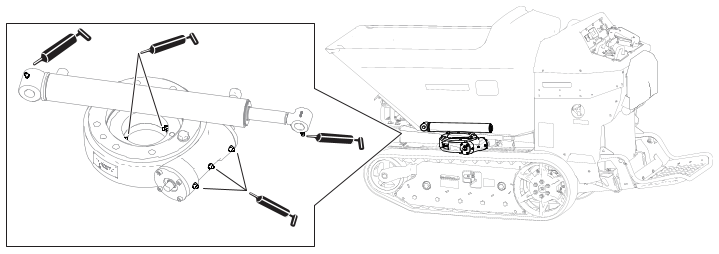
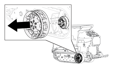
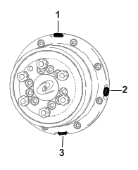
Changing the Drive-Motor Gear
Oil
-
Start the
machine and drive it for 5 minutes.
Note: This warms the gear oil so that it drains better.
-
Park the
machine on a level surface so that a drain plug on the front motor
is in the 6 o’clock position.
-
Shut off
the machine and remove the key.
-
Remove the
wheel drive.
-
Place a drain
pan under the drive motor.
-
Remove the
check and drain plugs and allow the gear oil
to drain.
-
Install the
drain plug.
-
Remove the
fill plug and fill the drive motor
with gear oil until the oil starts dripping from the check hole.
-
Install the
fill and check plugs.
-
Repeat the
procedure for the other drive motor.
-
Start the
machine and drive it for a few minutes.
-
Park the
machine on a level surface so that a drain plug is in the 3 o’clock position, shut off the machine,
and remove the key.
-
Remove the
plug in the 3 o’clock position and verify
that the oil level is at the bottom of the oil-level check hole. Add
oil as needed.
-
Install the
plug and torque plugs to 5
to 6 N∙m (50 to 60 in-lb).
Controls Maintenance
Adjusting the Controls
The factory
adjusts the controls before shipping the machine. However, after many
hours of use, you may need to adjust the traction
control alignment, the Neutral position
of the traction control, and the tracking of the traction control
in the full forward position.
-
Contact your
Authorized Service Dealer to adjust the controls of your machine.
Hydraulic System Maintenance
Hydraulic Fluid Specifications
| 68140
|
Mobil ATF Dexron
|
3.40 L (3.60 US qt) |
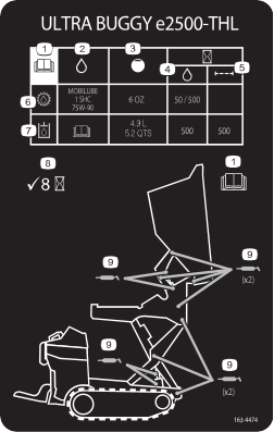
| 68142
|
Mobil ATF Dexron
|
4.90 L (5.20 US qt) |
Checking the Hydraulic Fluid
Model: 68140
Always use the correct hydraulic
fluid. Unspecified fluids will damage the hydraulic system.
|
Caution |
|
The hydraulic breather/filler
cap is designed to pressurize the reservoir to 34 kPa (5 psi).
Loosen
the cap slowly to avoid injury whenever adding oil or working on the
hydraulic system. Use a wrench on the hex directly
under the cap.
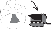
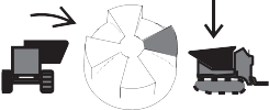
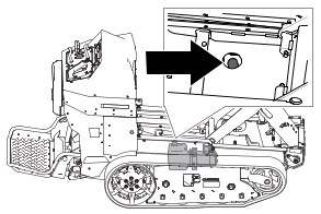
-
Rotate the
hopper, put it in the dump position  , and install the cylinder lock.
-
Shut off
the machine, remove the key, and allow the machine to cool.
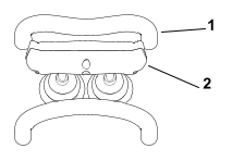
-
Lift the
lid on the hydraulic storage area  .
.
-
Clean the
area around the filler neck  of the hydraulic tank.
-
Remove the
filler-neck cap.
-
Wipe the
dipstick with a clean cloth and insert it into the reservoir without
threading it in.
-
Remove and
check the fluid level on the dipstick.
The fluid level should be between
the marks on the dipstick.
-
If the level
is low, add enough fluid to raise it to the proper level.
-
Install the
filler-neck cap.
Checking the Hydraulic Fluid
Model: 68142
Always use the correct hydraulic
fluid. Unspecified fluids will damage the hydraulic system.
|
Caution |
|
The hydraulic breather/filler
cap is designed to pressurize the reservoir to 34 kPa (5 psi).
Loosen
the cap slowly to avoid injury whenever adding oil or working on the
hydraulic system. Use a wrench on the hex directly
under the cap.
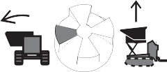
-
Raise and
dump the hopper, and install the safety lock.
-
Shut off
the machine, remove the key, and allow the machine to cool.
-
Clean the
area around the filler neck of the hydraulic tank.
-
Remove the
filler-neck cap.
-
Wipe the
dipstick with a clean cloth and insert it into the reservoir without
threading it in.
-
Remove and
check the fluid level on the dipstick.
The fluid level should be between
the marks on the dipstick.
-
If the level
is low, add enough fluid to raise it to the proper level.
-
Install the
filler-neck cap.
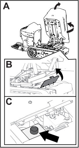
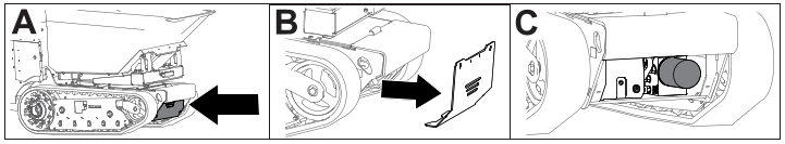
Changing the Hydraulic Fluid
Model: 68140
|
Caution |
|
The hydraulic breather/filler
cap is designed to pressurize the reservoir to 34 kPa (5 psi).
Loosen
the cap slowly to avoid injury whenever adding oil or working on the
hydraulic system.
-
Park the
machine on a level surface and shut off the machine.
-
Remove the
access panel.
-
Slowly loosen
the hydraulic tank cap.
-
Place a large
drain pan under the drain plug located at the bottom of the hydraulic
tank.
-
Remove the
drain plug and allow the oil to drain into the pan.
-
Install and
tighten the drain plug.
Note: Dispose of the used oil at a certified recycling center.
-
Torque the
drain plug to 1.1
to 1.4 N∙m (10 to 12 in-lb).
-
Install the
access panel.
-
Fill the
hydraulic tank with the specified fluid.
-
Install the
cap.
Changing the Hydraulic Fluid
Model: 68142
|
Caution |
|
The hydraulic breather/filler
cap is designed to pressurize the reservoir to 34 kPa (5 psi).
Loosen
the cap slowly to avoid injury whenever adding oil or working on the
hydraulic system.
-
Park the
machine on a level surface and shut off the machine.
-
Remove the
access panel.
-
Slowly loosen
the hydraulic tank cap.
-
Place a large
drain pan under the drain plug located at the bottom of the hydraulic
tank.
-
Remove the
drain plug and allow the oil to drain into the pan.
-
Install and
tighten the drain plug.
Note: Dispose of the used oil at a certified recycling center.
-
Torque the
drain plug to 1.1
to 1.4 N∙m (10 to 12 in-lb).
-
Install the
access panel.
-
Fill the
hydraulic tank with the specified fluid.
-
Install the
cap.
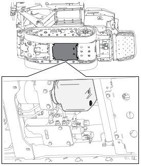
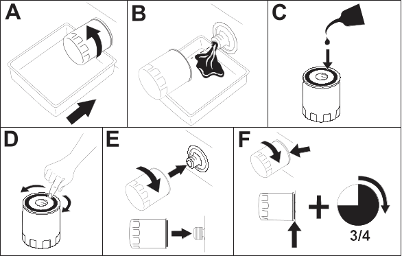
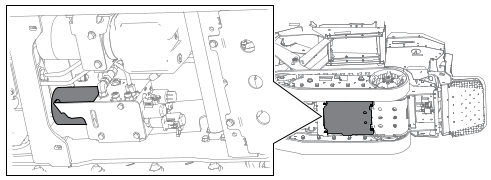
Replacing the Hydraulic Filter
Model: 68140
Do not use an automotive oil filter,
or severe hydraulic system damage may result.
-
Park the
machine on a level surface, shut off the machine, and allow the machine
to cool.
-
Place a drain
pan under the filter and replace it:
-
Clean up
any spilled fluid.
-
Start the
machine and let it run for 2 minutes to purge air from the system.
-
Shut off
the machine and check for leaks.
-
Check the
fluid level in the hydraulic tank.
Replacing the Hydraulic Filter
Model: 68142
Do not use an automotive oil filter
or severe hydraulic system damage may result.
-
Park the
machine on a level surface, shut off the machine, and allow the machine
to cool.
-
Place a drain
pan under the filter and replace it as shown:
-
Clean up
any spilled fluid.
-
Start the
machine and let it run for 2 minutes to purge air from the system.
-
Shut off
the machine and check for leaks.
-
Check the
fluid level in the hydraulic tank.
Checking the Hydraulic Lines
-
Check the
hydraulic lines for leaks, loose fittings, kinked lines, loose mounting
supports, wear, and deterioration. Make
necessary repairs before operating.
Cleaning
Removing Debris
-
Park the
machine on a level surface, shut off the machine, and remove the key.
-
Clean any
debris from the machine.
Blow
the dirt out rather than wash it out. If you use water, keep it away
from electrical items and hydraulic valves.
Clean electrical
connectors using compressed air; do not use contact cleaner.
Washing the Machine
When pressure-washing the
machine, do the following:
- Wear appropriate personal protective
equipment for the pressure washer.
- Keep all guards in place on the
machine.
- Avoid spraying at electronic components.
- Avoid spraying at edges of decals.
- Spray the exterior of the machine
only. Do not spray directly into openings in the machine.
- Spray only the dirty parts of
the machine.
- Use a 40-degree or larger spray
nozzle. 40-degree nozzles are usually white.
- Keep the tip of the pressure washer
at least 61 cm (2 ft) away from the surface being washed.
- Use only pressure washers with
pressure below 13790 kpa (2000 psi) and flow below 7.6 L (2 US gallons)
per minute.
- Replace damaged or peeling decals.
- Grease all grease points after
washing.
Troubleshooting
The machine does not drive.
| Possible Cause |
Corrective Action |
| The machine has been inactive
for more than 30 seconds and is in standby mode.
|
-
Push the
traction enable switch.
|
| The machine has been inactive
for more than 5 minutes and has shut off.
|
-
Restart the
machine.
|
| One or more of the electrical
connections are loose. |
-
Check and
tighten any loose connections.
|
The machine does not start.
| Possible Cause |
Corrective Action |
| The batteries need to be
charged. |
-
Check the
display for the battery status.
-
Charge the machine.
|
| The battery disconnect
switch is in the off position. |
-
Turn the
battery disconnect switch to the on position.
|
The machine batteries do not charge.
| Possible Cause |
Corrective Action |
| The electrical service
disconnect switch is in the off position.
|
-
Turn the
electrical service disconnect switch to the on position.
|
| The charging cord plug
is not fully plugged in. |
-
Ensure that
both sides of the charging cord is fully plugged in.
|
| The charger is bad. |
-
Contact your
Authorized Service Dealer.
|
The hopper is not functioning
properly.
| Possible Cause |
Corrective Action |
| The hydraulic fluid is
low. |
-
Check the
hydraulic fluid.
|
| There is air in the hydraulic
system. |
-
Bleed the
air out of the hydraulic system.
|
| The sensor is not working. |
-
Adjust the
sensor to 8 mm (5/16 inch) above the mounting bracket.
-
Check if the sensor has gone bad.
|
| The switch is loose or
disconnected. |
-
Check the
electric connections.
-
The switch has gone bad. Contact your Authorized Service Dealer.
|
| The hydraulic system is
damaged. |
-
Contact your
Authorized Service Dealer.
|