This kit is designed to aid in the mixing of chemicals in preparation for turf spray applications on well-maintained lawns in parks, golf courses, sports fields, and on commercial grounds. It is a dedicated attachment for a turf spray application vehicle and is intended to be used by professional, hired operators in commercial applications.
This product complies with all relevant European directives; for details, please see the separate product specific Declaration of Conformity (DOC) sheet.
Read this manual carefully to learn how to operate and maintain your product properly. The information in this manual can help you and others avoid injury and product damage. Although Toro designs and produces safe products, you are responsible for operating the product properly and safely.
You may contact Toro directly at www.Toro.com for product safety and operation training materials, accessory information, help finding a dealer, or to register your product.
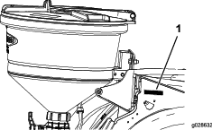
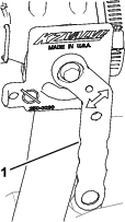
Whenever you need service, genuine Toro parts, or additional information, contact an Authorized Service Dealer or Toro Customer Service and have the model and serial numbers of your product ready. Figure 1 illustrates the location of the model and serial numbers on the product.
Safety
This manual identifies potential hazards and has safety messages identified by the safety-alert symbol (Figure 2), which signals a hazard that may cause serious injury or death if you do not follow the recommended precautions.

This manual uses 2 words to highlight information. Important calls attention to special mechanical information and Note emphasizes general information worthy of special attention.
Warning
Chemical substances used in the spray system may be hazardous and toxic to you, bystanders, animals, plants, soils, or other property.
-
Carefully read and follow the chemical warning labels and material safety data sheets (MSDS) for all chemicals used, and protect yourself according to the chemical manufacturer's recommendations. For example, use appropriate personal protective equipment (PPE), including face and eye protection, gloves, or other equipment to guard against personal contact with the chemical.
-
Keep in mind that there may be more than 1 chemical used, and you should assess information on each chemical.
-
Refuse to operate or work on the sprayer if this information is not available!
-
Before working on a spray system, make sure that the system has been triple rinsed and neutralized according to the recommendations of the chemical manufacturer(s).
-
Verify that there is an adequate supply of clean water and soap nearby, and immediately wash off any chemicals that contact you.
Safety and Instructional Decals
 |
Safety decals and instructions are easily visible to the operator and are located near any area of potential danger. Replace any decal that is damaged or missing. |


Installation
Note: Determine the left and right sides of the machine from the normal operating position.
Preparing to Install the Kit
-
Clean the sprayer; refer to Cleaning the Sprayer in the Operator’s Manual for the machine.
-
Park the machine on a level surface, engage the parking brake, shut off the engine, and remove the key; refer to the Operator’s Manual.
Installing the Eductor Valve and Hoses
Parts needed for this procedure:
| Eductor valve bracket (The bracket may already be installed from a previous kit installation) | 1 |
| Flange-head bolt (5/16 x 3/4 inch) | 2 |
| Flange locknut (5/16 inch) | 2 |
| Washer (5/16 inch) | 2 |
| Eductor valve assembly | 1 |
| Flange nut (1/4 inch) | 2 |
| Agitation bypass-hose assembly 25 x 305 mm (1 x 12 inches) (Model year 2023 and Before) | 1 |
| Pressure relief-hose | 1 |
| Supply-hose assembly | 1 |
Removing the Hoses
-
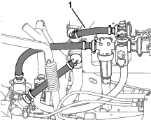
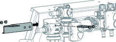
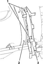
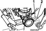
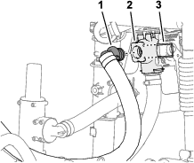
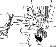
Move to the rear of the machine and locate the valve-mount bracket.
-
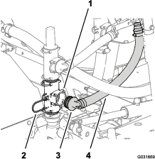
Remove the 3 hoses shown in Figure 3.
Note: Do not remove the agitation bypass hose on Model Year 2024 and After.
Note: Retain the hose clamps, gaskets, and retainers for installation in Installing the Bracket and Eductor Valve Assembly, Installing the Agitation Bypass Hose and Installing the Pressure Relief-Hose Assembly; discard the 3 hoses.
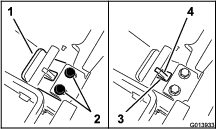
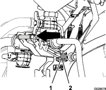
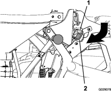
Repositioning the Pressure Relief Valve and Upper T-Fitting
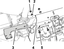
-
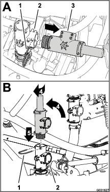
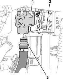
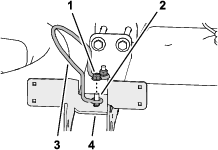
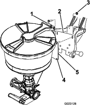
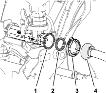
Remove the retainer that secures the pressure-relief valve to the T-fitting at the sprayer pump, and remove the relief valve (Figure 4).
-
Rotate the pressure relief valve up as shown in Figure 4.
Note: Align outlet of the pressure-relief valve rearward.
-
Insert the pressure-relief valve into the top of the T-fitting until the valve is fully seated (Figure 4).
-
Secure the pressure-relief valve to the T-fitting with the retainer that you removed in step 1.
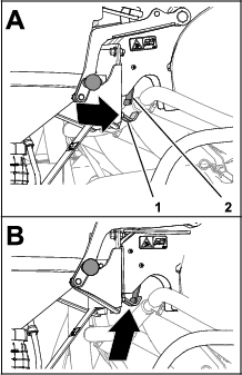
-
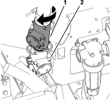
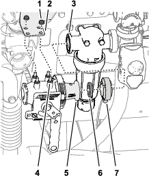
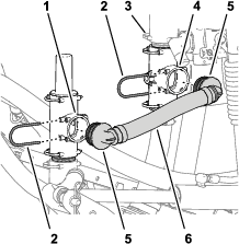
Rotate the upper T-fitting approximately 45° clockwise (Figure 5).
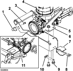
Installing the Bracket and Eductor Valve Assembly
-
Assemble the valve mount bracket to the front of the valve support (Figure 7) with the 4 flange-head bolts (5/16 x 3/4 inch), 4 flange locknuts (5/16 inch), and 4 washers (5/16 inch).
-
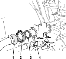
Align the flange of the reducer adapter (eductor valve) to the flange of the pressure-filter head (Figure 8) with the gasket that you removed in step 2 of Removing the Hoses.
-
Align the studs of the pressure-filter head through the holes in the valve mount bracket (Figure 8).
-
Assemble the flange of the reducer adapter to the flange of the pressure-filter head (Figure 8) with the flange clamp that you removed in step 2 of Removing the Hoses.
-
Secure the eductor valve top the valve mount bracket with the 2 flange locknuts (1/4 inch), and torque the nuts to 1017 to 1243 N∙cm (90 to 110 in-lb).
-
Tighten the flange clamp by hand.
Installing the Agitation Bypass Hose
-
Align the 90° barbed fitting of the new agitation bypass-hose assembly with the open port in the upper T-fitting and insert the 90° fitting until it is seated in the T-fitting (Figure 9).
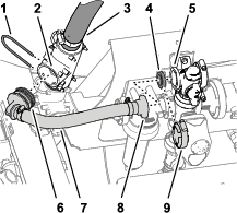
-
Secure the 90° barbed fitting to the T-fitting with the retainer (Figure 9) that you removed in step 2 of Removing the Hoses.
-
Align the straight flange fitting of the new agitation bypass-hose assembly and the gasket with the flange of the bypass valve (Figure 9).
-
Secure the straight flange fitting and gasket to the bypass valve with the flange clamp (Figure 9) that you removed in step 2 of Removing the Hoses.
Installing the Pressure Relief-Hose Assembly
-
Align the 90° fitting of the pressure relief-hose assembly with the open port in the upper T-fitting (located below the pressure-relief valve), and insert the 90° fitting until it is fully seated (Figure 10).
-
Secure the 90° T-fitting with the retainer (Figure 10) that you removed in step 2 of Removing the Hoses.
-
Align the other 90° fitting of the pressure relief-hose assembly with the open port of the lower T-fitting (secure to the valve mount) and insert the 90° fitting until it is fully seated (Figure 10).
-
Secure the 90° fitting to the upper T-fitting with the retainer (Figure 10) that you removed in step 2 of Removing the Hoses.
Installing the Supply-Hose Assembly
-
Align the other 90° fitting of the supply-hose assembly with the open port of the lower T-fitting at the sprayer pump and insert the 90° fitting until it is seated (Figure 11).
-
Secure the 90° fitting to the T-fitting at the sprayer pump with the retainer (Figure 11) that you removed in step 1 of Repositioning the Pressure Relief Valve and Upper T-Fitting.
-
Align the straight-barbed fitting of the pressure-hose assembly with the bottom port of the eductor valve and insert the straight fitting until it is seated (Figure 12).
-
Secure the straight-barbed fitting to the eductor valve (Figure 10) with a retainer.
Assembling the Frame
Parts needed for this procedure:
| Eductor mount | 1 |
| Flange locknut (5/16 inch) | 1 |
| Back plate assembly | 1 |
| Right cradle arm | 1 |
| Left cradle arm | 1 |
| Bushing | 2 |
| Pivot pin | 2 |
| Jam nut (3/8 inch) | 2 |
| Handle | 2 |
| Bolt (3/8 x 1-1/4 inches) | 2 |
| Set screw | 2 |
| Hairpin | 2 |
| Flat washer | 2 |
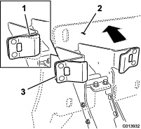
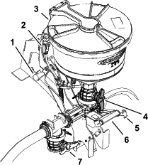
Installing the Support Frame to the Tank
-
Remove the 2 flange locknuts securing the tank-lid stop to the 2 carriage bolts at the rear strap of the sprayer tank, and remove the tank-lid stop (Figure 13).
Note: Retain the tank-lid stop and flange locknut.
-
Align the slots in the eductor mount to the 2 lower carriage bolts of the rear tank strap as shown in Figure 14.
-
Loosely assemble the flange locknut (5/16 inch) onto the lower carriage bolt (Figure 14).
-
Assemble the tank-lid stop and 2 flange locknut that you removed in step 1 onto the 2 upper carriage bolts (Figure 15).
-
Torque the 3 flange locknuts to 1978 to 2542 N∙cm (175 to 225 in-lb).
Preparing the Cradle Arms
-
Assemble the pivot pin through the upper hole in the cradle arm (Figure 16).

-
Apply medium-grade, thread-locking compound to the threads of the bolt (3/8 x 1-1/4 inch).
-
Assemble the bolt (3/8 x 1-1/4 inch) through the lower hole in the cradle arm and the retainer of the pivot pin (Figure 16) with the jam nut (3/8 inch), and tighten the jam nut to 15 to 17 N∙m (11 to 13 ft-lb).
-
Thread the handle onto the bolt (3/8 x 1-1/4 inch) and tighten the handle against the jam nut and tighten the handle by hand (Figure 16).
-
Repeat steps 1 through 4 to the other cradle arm (Figure 16).
Assembling the Cradle Arms to the Support Frame
-
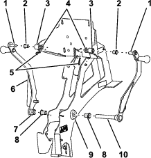
Insert a flanged bushing (3/4 inch inside diameter) into each end of the pivot tube in the main-support frame (Figure 17).
-
Insert a flanged bushing (1/2 inch inside diameter) into the left and right hubs of the back plate (Figure 17).
Note: Ensure that the flange of the bushings are aligned to the outward side of the hubs.
-
Assemble the lower pivot pin of the right cradle arm through the flanged bushing at the right side of the pivot tube and the pivot (Figure 17).
Note: Align the upper pivot pin of the arm with the right hub of the back plate.
-
Assemble the upper pivot pin of the right cradle arm through the right hub of the back plate (Figure 17).
-
Secure the upper pivot pin to the back plate with a washers (1/2 inch) and hairpin (Figure 17).
-
Assemble the hub of the left cradle arm over the end of the lower pivot pin of the right cradle arm that is protruding to the left of the left flanged bushing in pivot tube (Figure 17).
Note: Align the upper pivot pin of the arm with the left hub of the back plate.
-
Assemble the upper pivot pin of the left cradle arm through the left hub of the back plate (Figure 17).
-
Secure the upper pivot pin of the left cradle arm to the back plate with a washer (1/2 inch) and hairpin (Figure 17).
-
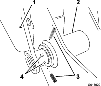
Install 2 set screws to the left arm at the lower hinge point (Figure 18).
Note: Do not tighten the set screw at this time to allow for later adjustment of the cradle system.
Installing the Latching Components
Parts needed for this procedure:
| Spring | 2 |
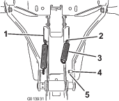
Installing the Springs
-
Install the spring in the hole in the lower end of the angled tab on the side of the frame assembly (Figure 19).
-
Hook 1 end of the spring into the hole and the other end onto the spring post (Figure 19).
-
Make sure that the spring end is seated properly in the groove in the post (Figure 19).
-
Repeat steps 1 through 3 for the other side.
-
Tighten the 2 set screws in the left arm.
Adjusting the Tongue Position
Move the cradle assembly into the upper transport position to adjust the tongue.
-
Lift up on the handles to raise the assembly while slightly tipping it toward the tank.
-
Guide the tongue under the crossbar with the welded tab in the upper portion of the frame assembly.
-
Let the assembly pivot down, toward the tank.
-
Making sure that the plastic stops are in contact with the spring tabs, apply enough pressure against the back plate assembly of the cradle to compress the spring tabs midway (Figure 20).
-
While maintaining the pressure on the back plate, slide the tongue toward you until the lip of the tongue plate contacts the crossbar (Figure 21).
-
Tighten the fasteners in the tongue to secure its position, then release pressure on the back plate.
Note: Check to see if there is any play in the cradle. It should be held snug to the frame assembly. You can repeat this procedure once the eductor is installed to adjust the locked position.
Installing the Eductor
Parts needed for this procedure:
| Handle | 1 |
| Socket-head screw (#10-24 x 1/2 inch) | 2 |
| Latch post | 1 |
| Spring clip | 1 |
| Bolt (#10-24 x 1/2 inch) | 2 |
| Locknut (#10-24) | 2 |
| Eductor | 1 |
| Flange-head bolt (5/16 x 3/4 inch) | 2 |
| Flanged-locknut (5/16 inch) | 2 |
| Latch handle | 1 |
| Bolt (3/8 x 1 inch) | 4 |
| Flanged-serrated nut (3/8 inch) | 4 |
| T-fitting and drain valve | 1 |
| Gasket | 1 |
| Flange clamp | 1 |
Assembling the Eductor Handle
Note: You can install the latch handle and latch post at either the left or right side of the eductor handle.
-
Assemble the latch post to the handle of the eductor (Figure 22) using the 2 socket-head screws (#10-24 x 1/2 inch).
-
Assemble the spring clip to the latch handle (Figure 22) with the 2 bolts (#10-24 x 1/2 inch) and 2 locknuts (#10-24).
-
Assemble the handle to the mount plate for the eductor (Figure 22) with 2 flange-head bolts (5/16 x 3/4 inch) and flange locknuts (5/16 inch).
-
Lower the cradle into the down position.
Assembling the Eductor to the Sprayer
-
Align the holes in the eductor mount plate with the slots in the cradle support frame (Figure 23).
Note: The fasteners need to be loose enough so that they can travel in the slot when the eductor is initially raised up into the transport position. This allows you to adjust the travel and alignment of the eductor.
-
Install 4 bolts (3/8 x 1 inch) and locknuts (3/8 inch) to mount the eductor.
Note: Do not tighten the bolts at this time.
-
To carefully raise the eductor in the cradle assembly up to the transport position, do the following:
-
Lift the lower handle to raise the eductor while slightly tipping it toward the tank.
-
Guide the tongue under the crossbar with the welded tab in the upper portion of the frame assembly.
-
Then pivot the assembly toward the tank, taking care to line up the spring clip with the large pivot tube in the lower portion of the frame.
-
Push until the spring clip snaps over the pivot tube as shown in Figure 24.
-
-
Check the eductor height on the cradle back plate and adjust as necessary.
-
Tighten the fasteners securing the eductor to the cradle.
Note: Torque the fasteners to 36 to 45 N∙m (27 to 33 ft-lb).
-
Tighten the 2 set screws on the left hand pivot arm, refer to Figure 18 in Assembling the Cradle Arms to the Support Frame.
-
Check the overall position of the eductor assembly on the tank strap.
Note: The eductor should be upright, in the transport position. Loosen the lower locknut on the frame assembly securing it to the tank. Do not remove the locknut. Adjust the position as necessary and tighten the locknut. Make sure that the strap is secure to the tank.
Assembling the T-fitting and Drain Valve
Installing the Forward Hose
Parts needed for this procedure:
| Bulkhead fitting | 1 |
| Seal | 1 |
| Locking ring | 1 |
| Carriage bolt (5/16 x 1 inch) | 1 |
| Eductor hose assembly | 1 |
| Flange locknut (5/16 inch) | 1 |
| Retainer | 1 |
| R-clamp (5/16 inch) | 1 |
| Gasket | 1 |
| Flange clamp | 1 |
Drilling the Tank
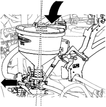
-
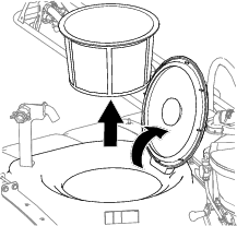
Open the lid of the spray tank and remove the filter basket (Figure 26).
-
Locate the forward location on the top of the tank as shown in Figure 27.
Note: Locate the drill mark in the center of the molded circle.
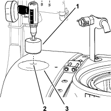
-
Use a 9 cm (3-5/8 inch) hole saw to drill a hole at the drill mark (Figure 27).
Note: You will need to increase the diameter slightly to accommodate the bulkhead.
-
After drilling the hole, remove any rough edges in the cut, and remove any debris that entered the spray tank during the cutting process.
Installing the Bulkhead
-
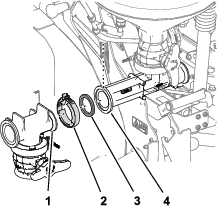
Install the seal over the bulkhead fitting (Figure 28).
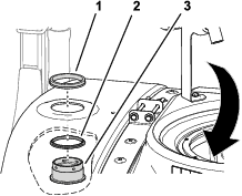
-
Install the bulkhead fitting and the seal through the hole that you created in Drilling the Tank, from inside the tank (Figure 28).
-
Secure the bulkhead to the tank with the locking ring (Figure 28).
-
Install the filter basket and close the lid of the spray tank.
Installing the Eductor Hose Assembly
-
Remove the 2 bolts (3/8 x 7 inches), 4 washers (3/8 inch), and 2 locknuts (3/8 inch) that secure the front strap halves of the spray tank (Figure 29).
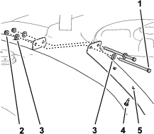
-
Insert the carriage bolt (5/16 x 1 inch) into the second hole in the strap half as shown in Figure 29.
-
Assemble the 2 front strap halves with the 2 bolts 4 washers, and 2 locknuts that you removed in step 1, and tighten the bolts and nuts by hand (Figure 29).
-
Install an R-clamp over eductor hose assembly (Figure 30).
-
Assemble the 90º barbed fitting of the eductor hose assembly into the bulkhead fitting and secure the barbed fitting to the bulkhead fitting a retainer (Figure 30).
-
Loosely assemble the R-clamp onto the carriage bolt and secure the clamp (Figure 30) with a flange locknut (5/16 inch).
Note: You will tighten the flange nut after the other end of the eductor hose assembly is installed.
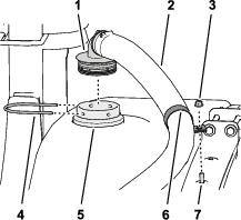
-
Attach the straight-barb fitting of the eductor hose assembly to the flange of the T-fitting for the eductor using a gasket and flange clamp, and tighten the clamp by hand (Figure 31).
-
Raise and lower the handle of the eductor to ensure that the eductor moves freely.
Note: If needed, adjust the position of the R-clamp to align the eductor hose (Figure 30).
-
Tighten the flange locknut (5/16 inch) that secures the R-clamp to the carriage bolt to 1978 to 2542 N∙cm (175 to 225 in-lb).
Installing the Supply Hose
Parts needed for this procedure:
| Eductor supply hose | 1 |
| Flange clamp | 1 |
| Gasket | 1 |
| Retainer | 1 |
-
Loosely assemble the straight-barb fitting of the eductor supply hose onto the flange of the eductor with a gasket and flange clamp (Figure 32).
-
Route the other end of the eductor supply hose past the spray pump and turn toward the eductor shutoff valve.
-
Assemble the 90º barbed fitting of eductor supply hose into the open port of the eductor shutoff valve (Figure 33).
-
Secure the barbed fitting to the shutoff valve with a retainer (Figure 33).
-
Tighten the flange clamp that secures eductor supply hose to the eductor by hand.
Finishing the Installation
Parts needed for this procedure:
| Suction lance and hose (optional) | 1 |
Note: The suction lance and hose are optional accessories. Contact your Authorized Toro Distributor for more information.
Retain the suction lance and hose for later use. Read and retain the remaining documentation on using the Chemical Pre-Mix Kit.
Operation
Caution
Chemicals are hazardous and can cause personal injury.
-
Read the directions on the chemical labels before handling the chemicals and follow all manufacturer recommendations and precautions.
-
Keep chemicals away from your skin. Should contact occur, wash the affected area thoroughly with soap and clean water.
-
Wear goggles and any other protective equipment recommended by the chemical manufacturer.
Controls
Lid
Rotate the lid counter clockwise to open it. Close the lid completely before turning it clockwise to lock it. You must close the lid and lock it before it is raised to the transport position.
Handles and Transport Strap
Use the upper and lower handles (Figure 34) to raise and lower the eductor and to lock it into the transport position.
Hopper Valve
Use the hopper valve to introduce chemicals from the eductor into the hose leading to the spray tank.
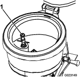
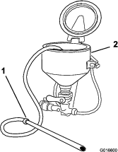
Bottle Rinse
The bottle rinse (Figure 35) is located inside the eductor tank. Use the bottle rinse to remove chemical residue from the inside of the container (bottle) in which the chemical is packaged. The bottle rinse is pressurized with solution from the spray system. The chemical container (bottle) is rinsed with spray-system solution discharged at the spout of the bottle rinse.
Flush Valve
The flush valve (Figure 34) is used to rinse residual chemical from the inside of the hopper of the eductor. The flush valve pressurizes with solution from the spray system. Rotating the flush-valve handle 90° counterclockwise to rinse the hopper; rotating the flush-valve handle 90° clockwise to closes the valve.
Lowering and Raising the Eductor
Lowering the Educator
-
Grasp the eductor handle and pull the latch handle off the latch post.
-
Grasp the eductor handle at the top of the cradle in addition to the eductor handle and pull the eductor handle out until the spring clip releases from the pivot tube.
-
Pull the eductor handle outward and down until the hook of the latch at the inboard side of the back plate is clear of the latch rod of the main support-frame assembly.
-
Fully lower the eductor while holding the eductor handle outward slightly.
Note: You will need to tip the bottom of the eductor outward so that you can align the hook of the latch under the spring plate at the bottom of the main-support frame.
-
When the latch of the back plate is under the spring plate, rotate the eductor handle inward so that the hook portion of the latch is aligned behind the spring plate.
Raising the Educator
-
Grasp a handle at the top of the cradle in addition to the eductor handle and pull the eductor handle outward until the hook portion of the latch is aligned outward of the spring plate (Figure 38 and Figure 41).
-
Raise the eductor while holding the eductor handle outward slightly (Figure 40).
Note: Tip the top of the eductor inward as needed so that you can align the latch at the inboard side of the back plate under the latch rod of the main-support-frame assembly.
-
Push in the handles at the top of the cradle until the hook portion of the latch is aligned behind the latch rod of the main-support frame (Figure 39).
-
Push in the eductor handle so that the hook raises to the latch rod and the spring clip fully seats around the pivot tube (Figure 38).
-
Pull the latch handle onto the latch post (Figure 37).
Protecting the Turf when Operating a Stationary Machine
Important: Under some conditions, heat from the engine, radiator, and muffler can potentially damage the grass when operating the sprayer in a stationary mode. Stationary modes include tank agitation, hand spraying, or using a walking boom.
Take the following precautions:
-
Avoid stationary spraying when conditions are very hot and/or dry, as turf can be more stressed during these periods.
-
Avoid parking the machine on the turf while stationary spraying. Park the machine on a cart path whenever possible.
-
Minimize the amount of time that the machine is left running over any particular area of turf. Both time and temperature affect how much the grass may be damaged.
-
Set the engine speed as low as possible to achieve the desired pressure and flow. This minimizes the heat generated and the air velocity from the cooling fan.
-
Allow heat to escape upward from the engine compartment by raising the engine guard/seat assemblies during stationary operation rather than being forced out under the vehicle. Refer to your Operator’s Manual for more information on raising the seat assemblies.
Note: Use a heat-shield blanket underneath the vehicle during stationary operation for additional heat protection. Contact your Authorized Toro Distributor to obtain a Toro heat-shield blanket kit for turf sprayers.
Using the Eductor
The following procedures assume the following operational states exist for the standard tank agitation: The sprayer is started and running, the pump is engaged and set to the desired pressure, and the throttle is in the mid-range position.
Starting the Eductor
Note: Close the hopper valve and flush valve before starting the eductor.
-
Use the lower handle to lower the eductor (Figure 42).
-
Open the lid to check for foreign objects which may hinder performance or contaminate the system (Figure 42).
-
Close and lock the lid by turning the cover clockwise.
-
Rotate the handle of the eductor shutoff valve to open position (Figure 43).
The spray system pressurizes the eductor circuit.
-
Open the hopper valve (red knob) located on the bottom of the hopper (Figure 42).
-
Unlock and open the lid slowly by turning the cover counterclockwise.
Loading Liquid or Powdered Chemical into the Hopper
-
Open the eductor shutoff valve.
-
Open the hopper valve (Figure 42).
-
Pour the required amount of chemical into the hopper.
Note: Avoid splashing liquids or powdered chemicals outside of the hopper.
-
If applicable, rinse the empty chemical containers as follows:
-
Place the rim of the container over the bottle rinse and press down to open the valve; refer to Figure 35 in Bottle Rinse.
Solution will stream from the nozzle of the bottle rinse into the inverted container (bottle).
-
Lift up the chemical container to close the shut-off valve of the bottle rinse.
-
-
Rinse the hopper of the eductor as follows:
-
Close lid of the hopper and lock it by turning the cover clockwise.
-
Open the flush valve and rinse the hopper of the eductor for 20 seconds (Figure 42).
-
Close the flush valve (Figure 42).
-
Open the lid of the hopper and inspect for chemical residue.
Repeat step 1 and 2 as necessary to clean the hopper.
-
-
Raise the eductor and secure it with the transport strap (Figure 42).
-
Close the eductor shutoff valve and the hopper valve (Figure 42).
Loading Chemicals with the Optional Suction Lance
Note: Lance suction depends upon eductor pressure and flow. For best results, use pressure up to 10 bar (150 psi) maximum.
-
Insert the suction lance body into the eductor until the O-ring seals on the hopper drain.
-
Use the free end of the lance to pierce the bag or container to vacuum powdered or liquid chemical.
-
Place the lance end into a clean container of water to rinse the lance assembly.
-
Remove the lance body from eductor and drain any remaining fluid into the hopper.
-
Close the hopper valve (red handle).
Shutting off the Eductor
-
Close all the valves.
Note: Close the hopper valve first.
-
Remove all chemical residue.
-
Close and lock the hopper lid by turning the cover clockwise (Figure 42).
-
Return the agitation valve to the fully open position.
-
Close the eductor shutoff valve; refer to Figure 43 of Starting the Eductor.
-
Return the eductor to the transport position, and secure it with the transport strap (Figure 42).
Troubleshooting
| Problem | Possible Cause | Corrective Action |
|---|---|---|
| The eduction rate is low. |
|
|
| There is no rinsing or flushing action. |
|
|
| There are leaks at the fittings. |
|
|