Installation
Note: The loose parts are packaged in 3 model-specific bags, each clearly labeled, along with 1 bag that contains common parts.
Preparing the Machine
-
Park the machine on a level surface and set the parking brake.
-
Raise the hood; refer to your Operator’s Manual.
-
Raise the cargo box; refer to your Operator’s Manual.
-
Shut off the engine and remove the key.
-
Disconnect the negative-battery cable; refer to your Operator’s Manual.
-
Select the loose parts bag for your model and locate the common parts bag. Discard the unused parts bags.
Installing the Windshield Washer Fluid Kit
Parts needed for this procedure:
| Washer-fluid tank | 1 |
| Washer bottle mount bracket | 1 |
| Washer-fluid hose | 1 |
| Locknut (5/16 inch) | 4 |
| Carriage bolt (5/16 x 3/4 inch) | 4 |
| Wire harness | 1 |
| Male straight fitting | 1 |
| Female straight fitting | 1 |
| Flange-head screw (1/4 x 5/8 inch) | 4 |
| Locknut (1/4 inch) | 4 |
Installing the Washer-Fluid Tank
If you have the Storage Box Kit installed, discard the washer bottle bracket mount.
-
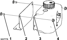
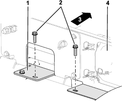
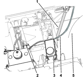
Install the washer-fluid tank to the storage box with the 4 flange-head screws (1/4 x 5/8 inch) and the 4 locknuts (1/4 inch) as shown in Figure 1.
-
Torque the locknuts to 1017 to 1243 N∙cm (90 to 110 in-lb).
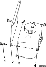
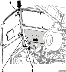
Installing the Washer-Fluid Tank
-
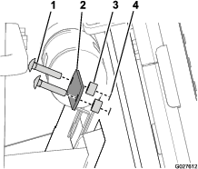
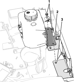
Install the washer-fluid tank to the washer bottle bracket mount with the 4 carriage bolts (5/16 x 3/4 inch) and 4 locknuts (5/16 inch) as shown in Figure 2.
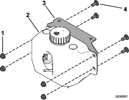
-
Torque the flange nuts (5/16 inch) to 1,987 to 2,542 N∙cm (175 to 225 in-lb).
-
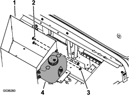
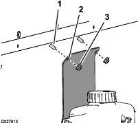
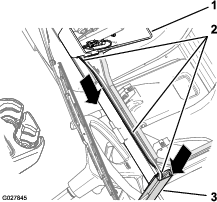
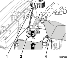
Install the washer bottle bracket mount to the dash reinforcement with the 2 flange-head screws (1/4 x 5/8 inch) and 2 locknuts (1/4 inch) as shown in Figure 3.
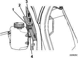
-
Torque the locknuts (1/4 inch) to 1,017 to 1,243 N∙cm (90 to 110 in-lb).
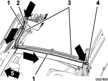
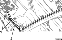
Routing and Connecting the Hose
-
Raise the machine with jack stands.
-
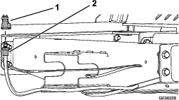
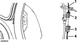
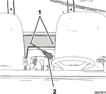
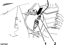
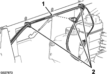
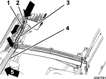
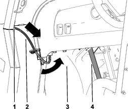
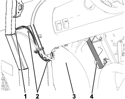
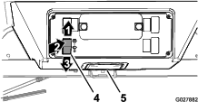
Connect the female straight fitting to the cab hose and the male straight fitting to the kit hose (Figure 4).
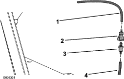
-
Connect the female straight fitting on the kit hose to the male straight fitting on the cab hose (Figure 5).
-
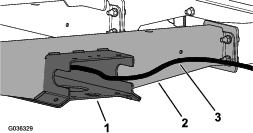
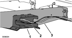
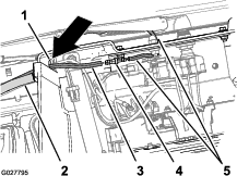
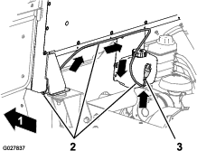
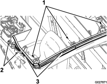
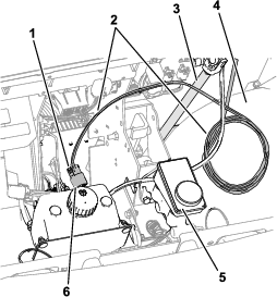
Route the kit hose along the floor-channel plate and through the opening in frame channel (Figure 6).
-
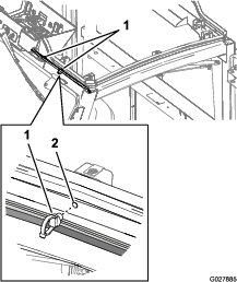
Route the kit hose through the opening in the top of the frame channel (Figure 7).
-
Secure the kit hose along the frame channel and as necessary.
-
Connect the kit to the pump; refer to Connecting the Hose to the Pump.
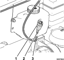
Connecting the Hose to the Pump
Routing and Connecting the Kit Wire Harness to the Cab Wire Harness
-
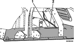
Connect the male connector on the kit wire harness to the female connector on the cab wire harness (Figure 9).
-
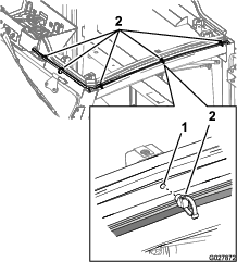
Route the kit wire harness along the floor-channel plate and through the opening in frame channel (Figure 10).
-
Route the kit wire harness through the opening in the top of the frame channel (Figure 11).
-
Secure the kit wire harness along the frame channel and as necessary.
Connecting the Kit Wire Harness to the Washer Pump
Connecting the Battery
-
Connect the negative-battery cable; refer to your Operator’s Manual.
-
Lower the cargo box and close the hood; refer to your Operator’s Manual.
Installing the Windshield Washer Fluid Kit
Parts needed for this procedure:
| Washer-fluid tank | 1 |
| Washer bottle mount bracket | 1 |
| Washer fluid hose | 1 |
| Carriage bolt (5/16 x 3/4 inch) | 2 |
| Locknut (5/16 inch) | 2 |
| Carriage bolt (1/4 x 1-1/4 inch) | 2 |
| Strap | 1 |
| Spacer (1/4 inch) | 2 |
| Locknut (1/4 inch) | 2 |
| Barbed hose connector | 1 |
| Wire harness | 1 |
| Push fastener | 8 |
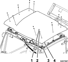
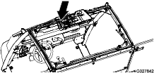
Removing the Roof Panel
Roof panel weight: 9.5 kg (21 lb)
-
Remove the 10 bolts (1/4 x 1 inch) and 10 sealing washers (1/4 inch) that secure the roof panel to the roof-support brackets of the cab (Figure 13).
Note: Retain the bolts and washers for installation of the roof panel in Installing the Overhead Console Plug and the Roof Panel.
-
Lift the roof panel straight up and remove it from the cab of the machine.
Note: Be careful when you set the roof panel down to avoid damaging the surface and edges of the panel.
-
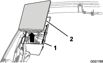
Remove the plug from the overhead console (Figure 14).
Installing the Washer-Fluid Tank
-
Assemble the washer-fluid tank to the washer bottle bracket-mount with the 2 carriage bolts (5/16 x 3/4 inch) and 2 locknuts (5/16 inch) as shown in Figure 15.
-
Torque the locknuts to 1,987 to 2,542 N∙cm (175 to 225 in-lb).
-
Locate the 2 holes 6.3 mm (1/4 inch) at the center of the rear panel of the cab (Figure 16).
Note: The holes are spaced apart 178 mm (7 inches).
-
Use an awl or punch to open a hole through the interior foam panel (Figure 17) at the hole locations that you identified in step 3.
Note: Use caution when working with sharp awl or punch.
-
Assemble the 2 carriage bolts (1/4 x 1-1/4 inches), strap, and 2 spacers (1/4 inch) to the holes that you made in the interior foam panel (Figure 18).
-
Assemble the washer bottle bracket mount and washer-fluid tank (Figure 19) onto the 2 carriage bolts (1/4 x 1-1/4 inches) with the 2 locknuts (1/4 inch).
-
Torque the flanged locknuts to 1,017 to 1,243 N∙cm (90 to 110 in-lb).
Connecting the Hose to the Wiper
-
At the overhead console, route 1 end of the hose through the hole in the overhead console (Figure 20).
-
Insert the small end of the barbed hose fitting into the end of the hose from the wiper arm until the fitting fully seats (Figure 20).
-
Insert the large end of the barbed hose fitting to the end of the hose until the fitting fully seats (Figure 20).
Routing the Hose
-
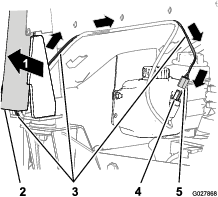
Route the hose to the left of the overhead console along the bulb seal at the front of the cab frame (Figure 21).
-
Route the hose rearward along the left frame channel of the cab (Figure 21).
-
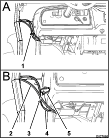
Route the free end of the hose into the opening at the top of the driver’s side pillar B of the cab frame, and down through the frame (Figure 22).
Note: Use a stiff piece of wire, about 173 cm (68 inch) long, to pull (fish) the hose through pillar B of the cab frame.
-
Route the free end of the hose across the back of the cab, and align the hose with the barbed fitting in the washer pump (Figure 23).
Connecting the Hose to the Pump
-
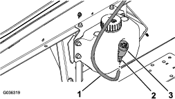
At the washer-fluid tank, align the end of the hose to the barbed fitting in the washer pump (Figure 24).
-
Push the hose onto the fitting until the hose fully seats onto the fitting (Figure 24).
Note: If the hose is too long, shorten it in step 9 of Securing the Wire Harness and Hose.
Connecting the Wire Harness at the Overhead Console
-
At the overhead console, route the 2-pin connector end of the wire harness for the washer pump through the hole in the overhead console (Figure 25).
-
Align the 2-pin connector of the washer pump wire harness to the 2-socket connector of the cab wire harness (Figure 25).
-
Push the 2 connectors together until the connector lock snaps secure (Figure 25).
-
Route the 2-socket connector of the wire harness for the washer pump to the left of the overhead console along the bulb seal at the front of the cab frame (Figure 25).
Routing the Wire Harness
-
At the overhead console, route the wire harness for the washer pump (Figure 26) to the left and along side of the hose installed in Routing the Hose.
-
Route the wire harness rearward along the left frame channel of the cab (Figure 26).
-
Route the 2-socket connector of the wire harness into the opening at the top of the driver’s side pillar B of the cab frame and down through the frame (Figure 27).
Note: Use a stiff piece of wire, about 173 cm (68 inch) long, to pull the wire harness through pillar B of the cab frame.
-
Route the wire harness for the washer pump across the back of the cab, and aligned to the 2-blade connector in the washer-pump motor (Figure 28).
Connecting the Wire Harness to the Washer Pump
Securing the Wire Harness and Hose
-
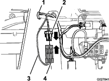
Remove the 2 harness clips that secure the cab wire harness to the front, left cab frame (Figure 30).
-
Install 2 push fasteners at the location where you removed the harness clips in step 1 (Figure 30 and Figure 31).
-
Secure the cab harness, washer-pump harness, and hose with the cable tie portion of the push fasteners (Figure 31).
Note: Tighten the cable tie only snug. Do not pinch or collapse the hose.
-
Remove the 3 push fasteners above the driver’s door frame (Figure 30).
-
Install 3 push fasteners at the location where you removed the push fasteners in step 4 (Figure 30 and Figure 31).
-
Secure the washer-pump harness and hose with the cable-tie portion of the push fasteners.
-
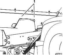
At the back of the cab, install 3 push fasteners into the 3 hole across the back panel of the cab (Figure 32).
-
Secure the washer-pump harness and hose with the cable tie portion of the push fasteners.
-
If needed, shorten the hose as follows:
Installing the Overhead Console Plug and the Roof Panel
-
Align the plug that you removed in step 3 of Removing the Roof Panel with the top opening of the overhead console (Figure 14).
-
Push the plug down into the overhead console until it is seated (Figure 14).
-
Align the holes in the roof panel with the clip nuts at the brackets of the cab frame (Figure 13).
-
Assemble the roof panel to the cab frame with the 10 bolts (1/4 x 1 inch) and 10 sealing washers (1/4 inch) as shown in Figure 13 that you removed in step 1 of Removing the Roof Panel.
-
Torque the bolts to 520 to 678 N∙cm (41 to 55 in-lb).
Connecting the Battery
-
Connect the negative-battery cable; refer to your Operator’s Manual.
-
Lower the cargo box; refer to your Operator’s Manual.
Installing the Windshield Washer Fluid Kit
Parts needed for this procedure:
| Washer-fluid tank | 1 |
| Washer bottle mount bracket | 1 |
| Washer fluid hose | 1 |
| Locknut (5/16 inch) | 2 |
| Carriage bolt (5/16 x 3/4 inch) | 2 |
| Barbed hose connector | 1 |
| Wire harness | 1 |
| Push fastener | 3 |
| Cable tie | 1 |
Removing the Roof Panel
Roof-panel weight: 9.5 kg (21 lb)
-
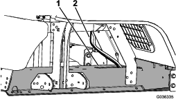
Remove the 10 bolts (1/4 x 1 inch) and 10 sealing washers (1/4 inch) that secure the roof panel to the roof-support brackets of the cab (Figure 33).
Note: Retain the bolts and washers for installation of the roof panel in Installing the Overhead-Console Plug and the Roof Panel.
-
Lift the roof panel straight up and remove it from the cab of the machine.
Note: Be careful when you set the roof panel down to avoid damaging the surface and edges of the panel.
-
Remove the plug from the overhead console (Figure 34).
Installing the Washer-Fluid Tank
-
Assemble the washer-fluid tank to the washer bottle mount bracket with the 2 carriage bolts (5/16 x 3/4 inch) and 2 locknuts (5/16 inch) as shown in Figure 35.
-
Torque the locknuts to 1,987 to 2,542 N-cm (175 to 225 in-lb).
-
At the lower headlight support, remove the 2 hex washer head bolts (1/4 x 7/8 inch), inboard of the right headlight, that secures the headlight brackets to the headlight (Figure 36).
Note: Retain the 2 hex washer head bolts (1/4 x 7/8 inch) for installation of the washer-fluid tank and washer bottle mount bracket.
-
Align the holes in the washer bottle mount bracket with the holes in the lower headlight support (Figure 37).
-
Assemble the tank-support bracket to the lower headlight support with the 2 hex washer head bolts (1/4 x 7/8 inch) that were removed in step 3 (Figure 37).
-
Torque the 2 bolts to 79 to 147 N∙cm (7 to 13 in-lb).
Connecting the Hose to the Wiper
-
At the overhead console, route 1 end of the hose through the hole in the overhead console (Figure 38)
-
Insert the small end of the barbed hose fitting into the end of the hose from the wiper arm until the fitting fully seats (Figure 38).
-
Insert the large end of the barbed hose fitting to the end of the hose until the fitting fully seats (Figure 38).
Routing the Hose
-
Route the hose to the left of the overhead console along the bulb seal at the front of the cab frame (Figure 39).
-
Route the free end of the hose into the opening at the top of pillar A (driver’s side) of the cab frame and down to the hole at the bottom of the pillar (Figure 39 and Figure 40).
Note: The hole is about level with the midpoint in the dash
Note: Use a stiff piece of wire, about 130 cm (51 inch) long, to pull the hose through pillar A of the cab frame.
-
Route the free end of the hose forward, between the fender and the steering column (Figure 40 and Figure 41).
-
Route the free end of the hose inboard toward the washer-fluid tank (Figure 41).
Connecting the Wire Harness at the Overhead Console
-
At the overhead console, route the 2-pin connector end of the wire harness for the washer pump through the hole in the overhead console (Figure 42).
-
Align the 2-pin connector of the washer pump wire harness to the 2-socket connector of the cab wire harness (Figure 42).
-
Push the 2 connectors together until the connector secures (Figure 42).
-
Route the 2-socket connector of the wire harness for the washer pump to the left of the overhead console along the bulb seal at the front of the cab frame (Figure 42).
Routing the Wire Harness
-
At the overhead console, route the wire harness for the washer pump (Figure 43) to the left and along side of the hose installed in Routing the Hose.
-
Route the 2-socket connector of the wire harness into the opening at the top of pillar A (driver’s side) of the cab frame and down to the hole at the bottom of the pillar (Figure 44).
Note: Use a stiff piece of wire, about 130 cm (51 inch) long, to pull the wire harness through pillar A of the cab frame.
-
Route the wire harness forward, between the fender and the steering column (Figure 44 and Figure 45).
-
Route the wire harness for the washer pump inboard toward the washer-fluid tank, and align the harness with the 2-blade connector on the washer-pump motor (Figure 45).
Connecting the Wire Harness to the Washer Pump
Securing the Wire Harness
-
Remove the 2 harness clips that secure the cab wire harness to the front, left cab frame (Figure 47).
-
Install 2 push fasteners at the location where you removed the harness clips in step 1 (Figure 47 and Figure 48).
-
Secure the cab harness, washer-pump harness, and hose with the cable tie portion of the push fasteners (Figure 48).
Note: Tighten the cable tie only snug. Do not pinch or collapse the hose.
-
Remove the harness clip that secures the cab wire harness to the lower forward-cab panel at the driver’s side of the machine (Figure 49).
-
Install a push fastener at the location where you removed the harness clip in step 4 (Figure 49).
-
Secure the cab harness, washer-pump harness, and hose with the cable tie portion of the push fastener (Figure 49).
-
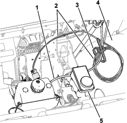
Coil the excess washer-pump harness (Figure 50), and secure the coiled harness and hose with a cable tie.
Installing the Overhead-Console Plug and the Roof Panel
-
Align the plug that you removed in step 3 ofRemoving the Roof Panel with the top opening of the overhead console (Figure 34).
-
Push the plug down into the overhead console until it fully seats (Figure 34).
-
Align the holes in the roof panel with the clip nuts on the brackets of the cab frame (Figure 33).
-
Assemble the roof panel to the cab frame with the 10 bolts (1/4 x 1 inch) and 10 sealing washers (1/4 inch) as shown in Figure 33 that you removed in step 1 of Removing the Roof Panel.
-
Torque the bolts to 520 to 678 N∙cm (41 to 55 in-lb).
Connecting the Battery
-
Connect the negative-battery cable; refer to your Operator’s Manual.
-
Lower the cargo box and close the hood; refer to your Operator’s Manual.
Operation
Using the Windshield Washer
Using the Wiper/Washer Control
Filling the Washer Tank
-
Access the washer tank as follows:
-
For HD-series Workman machines, raise the cargo bed and place the safety support on the lift cylinder; refer to your Operator’s Manual.
-
For GTX-series and MD-series Workman machines, raise the hood; refer to your Operator’s Manual.
-
-
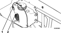
Remove the cap from the washer tank (Figure 52).
-
Add water or windshield-washer fluid through the filler neck of the tank to within 25 mm (1 inch) of the top of the tank (Figure 52).
Note: In climates where freezing temperatures occur, use all season (ethanol type) windshield-washer fluid.
-
Install the cap onto the filler neck securely (Figure 52).
-
Prepare the machine for operation as follows:
-
HD-series Workman machines— Remove the safety support from the bed lift cylinder, stow the safety support, and lower the bed; refer to your Operator’s Manual.
-
GTX-series and MD-series Workman machines—Lower the hood and secure it with the hood latches; refer to your Operator’s Manual.
-