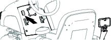
Important: Before installing this light kit on Sand Pro Model 08703 or Model 08705 machines with serial number 408784373 or lower, or on Model 08745 machines within the serial range of 411839064 through 411839074, you must install the Wire Harness Kit 140-0333.
Installation
Preparing the Machine
Parking the Machine
-
Park the machine on a level surface, move the traction pedal to the NEUTRAL position, move the throttle switch to the low-idle position, and lower the attachments; refer to your machine Operator’s Manual.
-
Engage the parking brake, shut off the engine, remove the key, and wait for all movement to stop before leaving the operator’s seat.
Disconnecting the Battery
Warning
Incorrect battery cable routing could damage the machine and cables, causing sparks. Sparks can cause the battery gasses to explode, resulting in personal injury.
-
Always disconnect the negative (black) battery cable before disconnecting the positive (red) cable.
-
Always connect the positive (red) battery cable before connecting the negative (black) cable.
Warning
Battery terminals or metal tools could short against metal components, causing sparks. Sparks can cause the battery gasses to explode, resulting in personal injury.
-
When removing or installing the battery, do not allow the battery terminals to touch any metal parts of the machine.
-
Do not allow metal tools to short between the battery terminals and metal parts of the machine.
-
At the back of the machine, remove the capscrew and nut that secures the negative battery cable to the battery post (Figure 1).
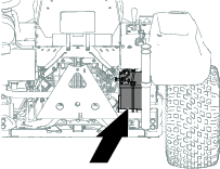
-
Position the battery cable so that it does not contact the negative battery post.
Removing the Center Shroud
Preparing the Lights
Parts needed for this procedure:
| Carriage bolt (5/16 x 1 inch) | 2 |
| Front support | 1 |
| Lock washer (3/16 inch) | 2 |
| Nut (3/16 inch) | 2 |
| Rear bracket | 1 |
Assembling the Carriage Bolt to the Light
-
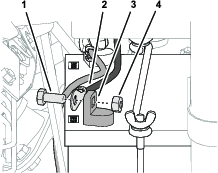
Remove the carriage bolt (3/16 x 2 inches) and nut (3/16 inch) that secures the bracket to the light (Figure 4).
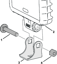
-
Assemble the carriage bolt (5/16 x 1 inch) into the pivot bracket as shown in Figure 5.
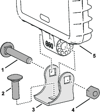
-
Assemble the bracket and carriage bolt (5/16 x 1 inch) to the light with the carriage bolt (3/16 x 2 inches) and nut (3/16 inch), and tighten the nut by hand (Figure 5).
-
Repeat steps 1 through 3 for the other light.
Assembling the Light to the Front Support
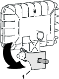
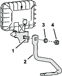
Assembling the Light to the Front Support
-
Assemble the light and carriage bolt to the front support with the lock washer (3/16 inch) and nut (3/16 inch) as shown in Figure 8.
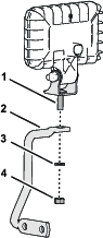
-
Tighten the nut by hand.
Assembling the Light to the Rear Bracket
-
Assemble the light and carriage bolt to the rear bracket with the lock washer (3/16 inch) and nut (3/16 inch) as shown in Figure 9.
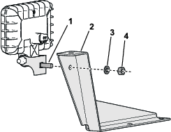
-
Tighten the nut by hand.
Routing the Wire Harness
Parts needed for this procedure:
| Wire harness | 1 |
-
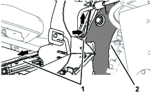
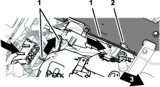
Route the 2-socket connector (labeled ), 8-socket connector, and the 2-pin connector of the LED light kit wire harness along the right frame channel and under the dash shroud (Figure 10 and Figure 11).
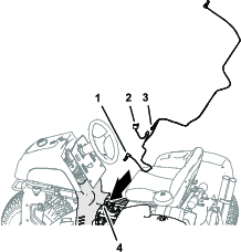
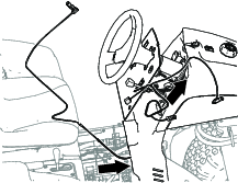
-
Route the kit wire harness up and along the steering-support tube (Figure 12).
-
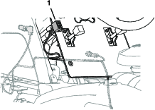
Route the 8-socket connector of the wire harness to the left side of the dash panel (Figure 13).
-
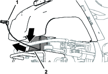
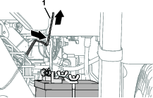
Route the 2-socket connector of the kit wire harness along the steering pivot and forward of the fuel tank (Figure 14).
-
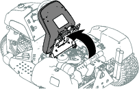
Rotate the operator’s seat forward (Figure 15).
-
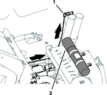
Route the wire harness along the right side of the machine, rearward along support tube for the console (Figure 16).
-
Route the 2-socket connector of the kit wire harness labeled up and to the right of the document tube (Figure 17).
Connecting the Dash Components
-
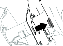
Remove the plug from the dash panel as shown in Figure 18.
-
Insert the switch into the opening in the dash panel (Figure 19).
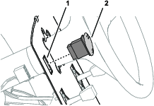
-
Plug the 8-socket connector of the kit wire harness onto the connector of the switch (Figure 20).
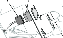
-
Plug the 2-pin of the kit wire harness into the 2-socket connector of the machine wire harness labeled (Figure 21).
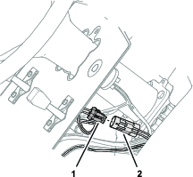
Installing the Front LED Lights
Parts needed for this procedure:
| R-clamp | 1 |
| Flange-head capscrew (5/16 x 3/4 inch) | 2 |
Assembling the Front Light to the Machine
-
Assemble the R-clamp over the wire harness as shown in Figure 22
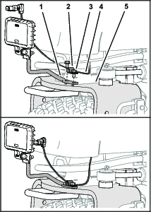
-
Align the holes in the front support and the R-clamp with the holes in the castor fork (Figure 22).
-
Assemble the front support and the R-clamp to the castor fork (Figure 22) with 2 flange-head capscrews (5/16 x 3/ inch).
-
Torque the capscrews to 1978 to 2542 N∙cm (175 to 225 in-lb).
Assembling the Front Light to the Machine
-
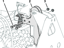
Remove the 2 capscrews (3/8 x 2 inches) and 2 locknuts (3/8 inch) that secure the guide brackets for the front lift kit to the caster-fork bracket (Figure 23).
-
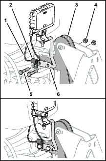
Assemble the R-clamp over the wire harness as shown in Figure 24.
-
Align the holes in the front support and the R-clamp with the holes in the guide bracket and the caster-fork bracket (Figure 24).
-
Assemble the front support and the R-clamp to the guide bracket (Figure 24) with the 2 capscrews (3/8 x 2 inches) and 2 locknuts (3/8 inch) that you removed in step 1.
-
Torque the capscrews and locknuts to 37 to 45 N∙m (27 to 33 ft-lb).
-
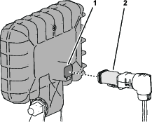
Plug the 2-socket connector of the kit wire harness labeled into the front LED light (Figure 25).
Assembling the Rear Light to the Machine
-
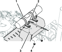
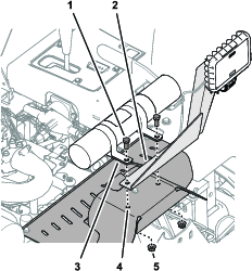
Remove the 2 capscrews (5/16 x 5/8 inch) and 2 flange locknuts (5/16 inch) that secure the document tube R-clamps to the rear cover of the machine (Figure 26).
-
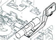
Align the holes in the R-clamps and the rear LED bracket with the holes in the rear cover (Figure 27).
-
Assemble the rear light bracket and the R-clamp to the rear cover (Figure 27) with the 2 capscrews (5/16 x 5/8 inch) and 2 locknuts (5/16 inch) that you removed in step 1.
-
Torque the capscrews and locknuts to 1978 to 2542 N∙cm (175 to 225 in-lb).
-
Plug the 2-socket connector of the kit wire harness labeled into the front LED light (Figure 28).
Securing the Wire Harness
Parts needed for this procedure:
| Cable tie | 5 |
-
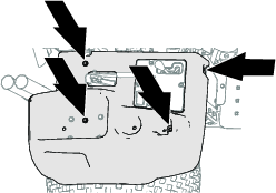
Fully loosen the 4 capscrews that secure the side-control console to the machine (Figure 29).
Note: Do not remove the control console from the machine.
-
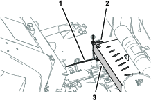
Secure the kit wire harness with a cable tie at the rear brace of the frame (Figure 30).
-
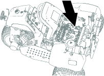
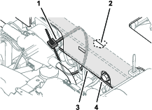
Lift the edge of the side-control console and wrap a cable tie around the right support tube (Figure 31).
-
Secure the kit wire harness to the right support tube with the cable tie (Figure 31).
-
Tighten the 4 capscrews that secure the side-control console to the machine (Figure 29).
-
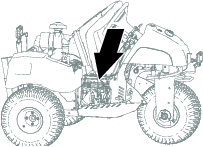
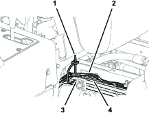
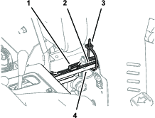
Secure the kit wire harness to the machine wire harness and hydraulic tube as shown in Figure 32.
-
Secure the kit wire harness to the machine wire harness and hydraulic tube as shown in Figure 33.
-
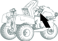
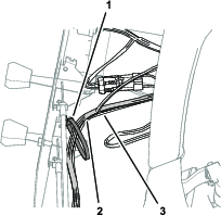
Secure the kit wire harness to the machine wire harness as shown in Figure 34.
Installing the Fuse
Parts needed for this procedure:
| Fuse (10 A) | 1 |
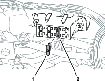
Insert the fuse (10 A) into slot 3 of the fuse block (Figure 35).
Finishing the LED Light Kit Installation
-
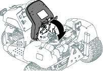
Rotate the operator’s seat down until it latches (Figure 36).
-
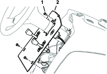
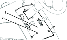
Align the holes in the dash panel with the holes in the frame bracket (Figure 37).
-
Secure the dash panel to the bracket with the 3 flange-head capscrews (Figure 37) that you removed in Disassembling the Dash Panel.
-
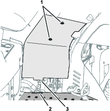
Align the tabs of the center shroud with the slots in the left and right footrests (Figure 38).
-
Thread the capscrews of the shroud evenly into the frame of the machine (Figure 38).
-
Connect the negative battery cable to the battery post with the capscrew and nut (Figure 39) that you removed in Preparing the Machine.