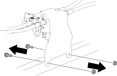
| 1
|
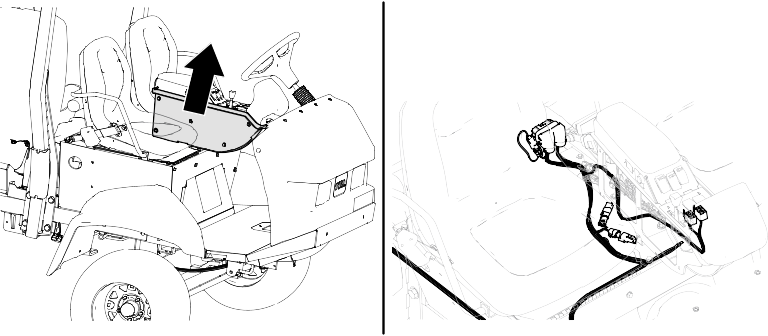
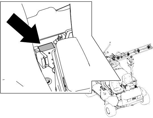
Manifold bracket
|
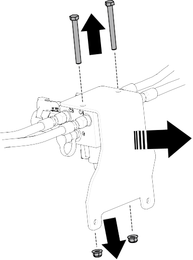
| 1
|
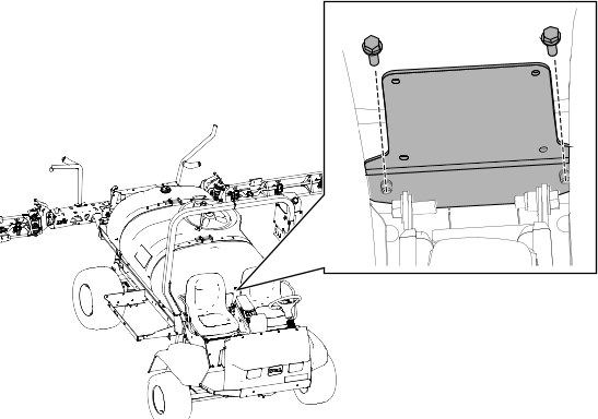
Mounting bracket
|
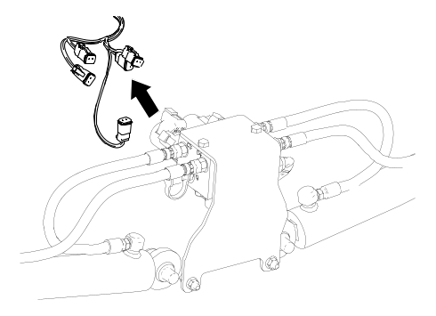
| 1
|
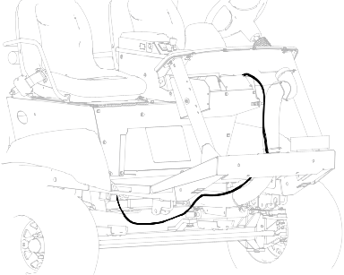
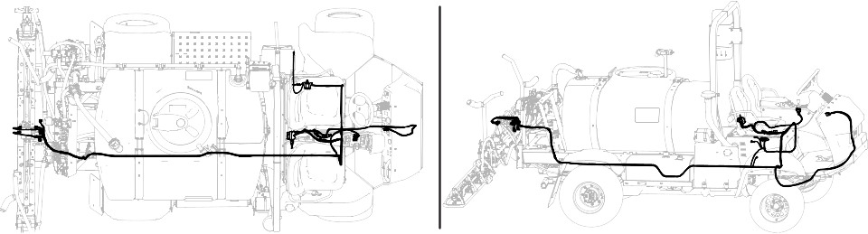
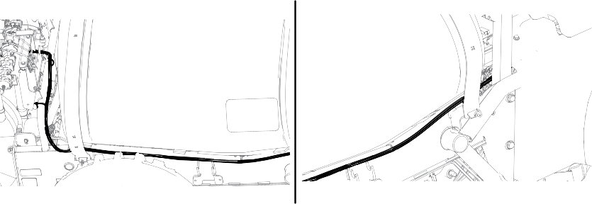
Wiring harness
|
| 1
|
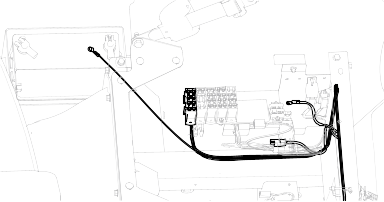
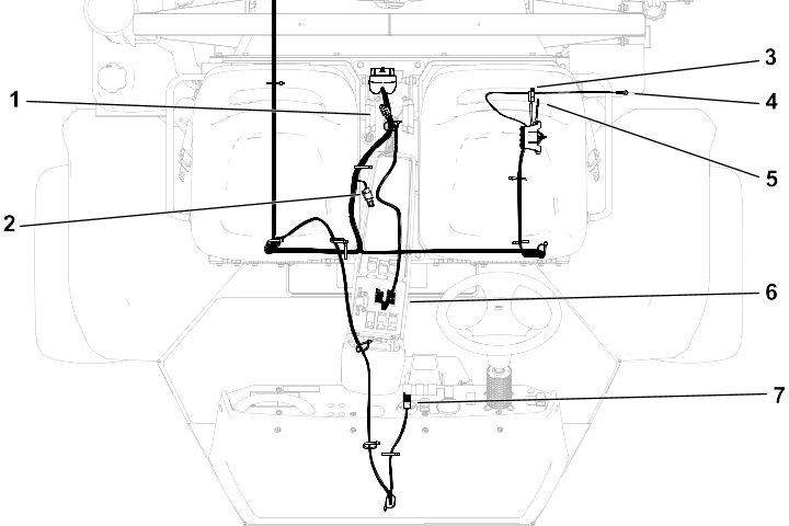
Wire harness |
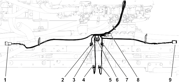
| Callout
|
Connector Type
|
Label
|
|---|---|---|
| 1
|
6 Pin
|
LEFT SONIC SENSOR |
| 2
|
2 socket
|
LEFT BOOM DOWN |
| 3
|
2 socket
|
LEFT BOOM UP |
| 4
|
2 socket
|
LEFT ENABLE |
| 5
|
2 socket
|
RIGHT ENABLE |
| 6
|
2 socket
|
RIGHT BOOM UP |
| 7
|
2 socket
|
RIGHT BOOM DOWN |
| 8
|
3 socket
|
CAN BUS TERMINATION |
| 9
|
6 socket
|
RIGHT SONIC SENSOR |
| Callout
|
Connector Type
|
Label
|
|---|---|---|
| 1
|
3 socket and cap
|
CAN DIAG CAP |
| 2
|
3 socket and cap
|
CAN BUS TERMINATION |
| 3
|
Blade
|
TO MAIN FUSE BLOCK |
| 4
|
Terminal
|
BATTERY |
| 5
|
Terminal
|
GROUND BLOCK |
| 6
|
8 socket (X2)
|
LEFT/RIGHT ACTUATOR SWITCH |
| 7
|
8 socket
|
MODE INDICATOR |