| 1
|
Wire harness
|
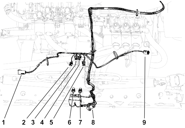
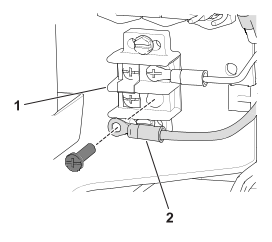
| Callout
|
Connector Type
|
Label
|
|---|---|---|
| 1
|
6 Pin
|
LEFT SONIC BOOM SENSOR |
| 2
|
2 socket
|
LEFT BOOM DOWN |
| 3
|
2 socket
|
LEFT BOOM UP |
| 4
|
2 socket
|
RIGHT BOOM UP |
| 5
|
2 socket
|
RIGHT BOOM DOWN |
| 6
|
2 socket
|
LEFT ENABLE |
| 7
|
2 socket
|
RIGHT ENABLE |
| 8
|
3 socket
|
TERMINATOR |
| 9
|
6 socket
|
RIGHT SONIC BOOM SENSOR |
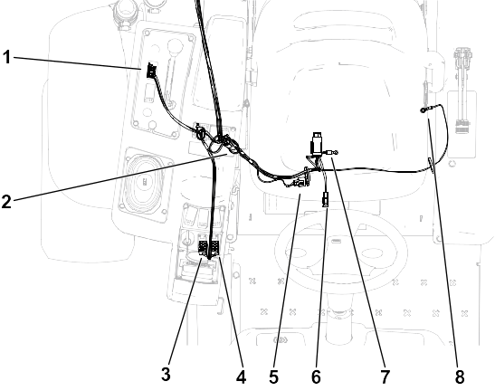
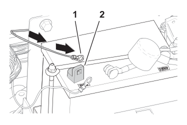
| Callout
|
Connector Type
|
Label
|
|---|---|---|
| 1
|
8 socket
|
MODE INDICATOR |
| 2
|
3 socket
|
TERMINATOR |
| 3
|
8 socket
|
RIGHT ACTUATOR SW |
| 4
|
8 socket
|
LEFT ACTUATOR SW |
| 5
|
3 socket
|
CAN DIAGNOSTIC PORT |
| 6
|
Blade
|
TO MAIN FUSE BLOCK |
| 7
|
Terminal
|
BATTERY – |
| 8
|
Terminal
|
BATTERY + |