| Maintenance Service Interval | Maintenance Procedure |
|---|---|
| Before each use or daily |
|
Introduction
This machine is a ride-on, reel-blade mower intended to be used by professional, hired operators in commercial applications. It is designed primarily for cutting grass on well-maintained turf. Using this product for purposes other than its intended use could prove dangerous to you and bystanders.
When operated in autonomous mode, this robotic reel-blade mower is intended to be used by professional, hired supervisors for autonomous turf care in commercial applications. It is designed primarily for cutting grass on well-maintained turf on properties that meet Toro requirements detailed in Autonomous Site Assessment Criteria. Using this product for purposes other than its intended use could prove dangerous to you and bystanders.
Read this information carefully to learn how to operate and maintain your product properly and to avoid injury and product damage. You are responsible for operating the product properly and safely.
Visit www.Toro.com for more information, including safety tips, training materials, accessory information, help finding a dealer, or to register your product.
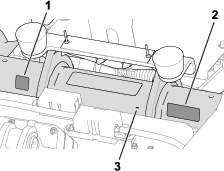
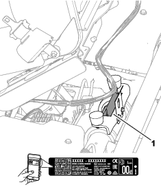
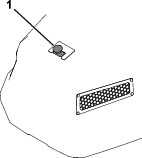
Whenever you need service, genuine Toro parts, or additional information, contact an authorized Toro distributor and have the model and serial numbers of your product ready. Figure 1 identifies the location of the model and serial numbers on the product. Write the numbers in the space provided.
Important: With your mobile device, you can scan the QR code on the serial number decal (if equipped) to access warranty, parts, and other product information.
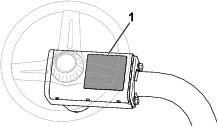
Safety-Alert Symbol
The safety-alert symbol (Figure 2) shown in this manual and on the machine identifies important safety messages that you must follow to prevent accidents.

The safety-alert symbol appears above information that alerts you to unsafe actions or situations and is followed by the word DANGER, WARNING, or CAUTION.
DANGER indicates an imminently hazardous situation which, if not avoided, will result in death or serious injury.
WARNING indicates a potentially hazardous situation which, if not avoided, could result in death or serious injury.
CAUTION indicates a potentially hazardous situation which, if not avoided, may result in minor or moderate injury.
This manual uses two other words to highlight information. Important calls attention to special mechanical information and Note emphasizes general information worthy of special attention.
Modes of Operation
This machine is designed to perform two modes of operation:
-
Manual mode: Mode of machine operation in which the machine functions are controlled by an operator.
-
Autonomous mode: Mode of machine operation in which a machine performs functions related to its defined tasks without operator interaction; instead, operation is monitored by a qualified supervisor.
Autonomous Site Assessment Criteria
Follow these guidelines for operating the machine(s) in autonomous mode at an acceptable site.
Definition of Terms
A direct path is a path that the machine(s) can follow without encountering obstructions while operating in autonomous mode.
An obstruction prevents the machine(s) from continually operating in autonomous mode. The object detection system is designed to stop the machine when it detects any of the following obstructions:
-
Fences (e.g., solid wall or chain link fence; rope and temporary fences are not adequate obstructions)
-
Retaining walls
-
Continuous rows of hedges or vegetation taller than 1 m (3.3 ft) or with no gaps larger than the width of the machine
-
Ditches
-
Streams
-
Lakes
-
Buildings
-
Slopes too steep for the machine(s) to traverse
-
Any other impassable terrain that the machine can not physically traverse
An autonomous operating area (AOA) is a supervisor-defined area where the machine(s) can follow a direct path while in autonomous mode.
A non-operating area (NOA) is a supervisor-defined area where the machine(s) is not allowed to follow a direct path while in autonomous mode.
An acceptable site meets all the criteria of the Autonomous Operating Area Site Safety Criteria.
Autonomous Operating Area Site Safety Criteria
Before enabling the machine to operate in autonomous mode, ensure that the boundary of the AOA is set at least 10 m (33 ft) away from any of the following hazards:
Note: Alternatively, if there is an obstruction (e. g., a solid wall or impassible terrain) between the machine and any of the following hazards, ensure that the boundary of the AOA is set at least 2 m (7 ft) away from the obstruction.
Public Roads
A public road is a road on which vehicles (e.g., automobiles, all-terrain vehicles, and bicycles) are allowed, but not pedestrians.
If public areas or trails are closed to the public during autonomous operations, the AOA boundary restrictions defined above do not apply.
Public Bicycle Trails
A public bicycle trail is a trail for daily, anytime use by the general public that allows the use of light two-wheeled vehicles (e.g., bicycles and scooters).
If public areas or trails are closed to the public during autonomous operations, the AOA boundary restrictions defined above do not apply.
Public Pedestrian Trails
A public pedestrian trail is a public path used by the general public which does not allow the use of vehicles.
If public areas or trails are closed to the public during autonomous operations, the AOA boundary restrictions defined above do not apply.
Deep Bunkers and Drop-Offs
A deep bunker or drop-off is a sand pit or depression that is 1.5 m (5 ft) or greater in depth within 1.0 m (39 inches) from the edge of the pit.
Maintenance Facilities
A maintenance facility includes the buildings and related outdoor areas used only by site personnel for maintaining and storing equipment, including the machine(s). The general public and other site personnel that are not maintaining equipment do not have access to the maintenance facility or related outdoor areas.
Private Property
Private property is any area that you do not have permission to access.
Slopes
Important: Excessive slopes can be included inside an AOA or less than 10 m (33 ft) away from an AOA boundary, but there must be an NOA boundary around them.
Measure the slope angles using a 1.25 m (4 ft) long piece of wooden board over the steepest part of the slope and placing an inclinometer on the board.
Do not allow machine(s) to operate in autonomous mode on excessive slopes as defined here;
-
Do not operate the machine on slopes greater than or equal to 14° (25% grade) for a horizontal distance greater than 10 m (33 ft).
-
Do not operate the machine on a slope greater than 15° (27% grade).
User Definitions
Qualified machine supervisor (Supervisor)
One or more individuals having the responsibility of overseeing the operation of the machine(s). A supervisor will have demonstrated:
-
Adequate machine control
-
A general understanding of the energy, powertrain, and control systems of the machine(s)
-
Been trained and read and understood the machine operator's manuals
Qualified manual operator (Operator)
One or more customer employees having the responsibility of manually driving the machine while it is in manual mode.
On-product emergency stop
An emergency-stop switch (e-stop) that is located on and attached to the machine. The switch functions only when the machine is in autonomous mode.
Mobile device
A supervisor’s mobile device (e.g., smart phone or tablet) that connects to the machine for programming, controlling, and monitoring the machine while it operates in autonomous mode. The device serves as the remote stop device that the supervisor must carry for stopping all functions of the machine(s) on command when necessary.
Terminology
Advisory—a message that informs the user of an operator error or anything that may cause a job to pause or halt and may require the user to intervene.
App—an abbreviation for software application. A computer program on a mobile device that performs one or more tasks. Also called application, mobile app, or web app.
Autonomous control system (ACS)—a system made up of software and hardware that enables a machine to perform tasks without human intervention for long periods of time.
Autonomous mode—a mode of machine operation in which a machine performs functions related to its defined tasks without operator interaction. Contrasts with manual mode.
Autonomous operating area (AOA)—area in which autonomous operation is allowed. Within this area, the machine may freely decide which trajectories to execute when going from one place to another. This is typically an area with low number of fixed obstacles. In a golf course setting, this area has at least part of a fairway or a pick-up point within it.
Base station—in the context of external land surveying, it is a GNSS receiver at an accurately known, fixed location used to derive correction information for nearby portable GNSS receivers. See also Global Positioning System; GNSS receiver.
Boundary—something that indicates or fixes a limit or extent. For a robot, it is the outside, no-cross line of an operating area, path, or exclusion area. Also called perimeter. See also Operating Area; Path; Exclusion Area.
Centerline—a line that extends down the middle of the entire fairway. For tuxedo-style mowing patterns, the machine follows the curvature of this line while mowing.
Contiguous mowing area (CMA)—area in which mowing operation is performed. It is represented on the map by the lighter green line inside an AOA. This defines the area that will be mowed by the machine. A CMA may have holes within it but it is a single closed area and must be fully within a single AOA. In a golf course, this typically corresponds to a fairway or a fairway portion in case of fairways that are split in multiple parts by natural hazards (e.g., a lake).
Direction of Play (D.o.P)—in golf terms, the direction of play is the direction from tee to green. During autonomous mowing, the direction of play can be used when creating custom mowing patterns. The machine can mow with or against the direction of play, or it can be programmed to mow at an angle from the direction of play.
Exclusion area—an area recorded by the operator that the robot shall not enter. See Non-operational area (NOA).
Fault—the result of a mechanical, sensor, or software error, which requires service or correction of the machine, sensor, or software code.
Global navigation satellite system (GNSS)—a general term describing the global set of constellations used for satellite localization. See also Global Positioning System.
Global positioning system (GPS)—a U.S.-based, satellite constellation-based navigation system that uses a digital signal from each satellite to send data to a receiver. This receiver can then determine its approximate distance to the satellite, as well as the geographic position (GP) of the satellite, which is the location on the earth directly below the satellite.
GNSS antenna—a device used for receiving and expanding radio signals sent by distinct frequencies coming from GNSS satellites. See also Global Navigation Satellite System; Global Positioning System.
GNSS receiver—a device that can receive information from GNSS satellites. Also called satellite navigation device. See also Global Navigation Satellite System.
Go to pick-up point—a behavior that consists of the machine autonomously returning to a predefined point when requested by the supervisor.
Hole—a type of recorded area by the operator inside of a CMA that the robot can traverse but shall not mow. Record an NOA within the Hole if the machine should never enter an area while operating autonomously; see Non-operating area (NOA).
Inter-AOA paths—paths that the machine may take to travel between AOAs. These are represented in the map by orange lines. These defined paths typically correspond to paths that human-driven machines already use. The machine will follow these paths exactly or very closely when traveling between AOAs.
LiDAR (laser imaging, detection, and ranging)—see Sensor types.
Localization—the process of determining where a mobile robot is with respect to a global reference frame. Localization is a most fundamental competency required by robot as the knowledge of its location is necessary for making decisions about future actions.
Manual mode—a mode of machine operation in which machine functions are controlled by an operator. Contrasts with autonomous mode.
Mapping—the procedure of collecting the location and shape of relevant features in the environment, storing them with precision in a global reference frame.
Mission—a set of tasks to be performed by the machine.
Navigation—the ability of a robot to determine its own position in its frame of reference and plan a path toward some goal location.
Non-operating area (NOA)—area in which autonomous operation is forbidden. This type of area is used to indicate a natural obstacle or obstruction, an area within an AOA, or an area within a CMA in which the machine should never enter while operating autonomously (e.g., lakes, sand bunkers, or holes).
Object—an obstacle or a ground condition that can cause harm, or is harmed if it comes into contact or collision with the machinery. Objects are able to be seen by the machine’s object detection system; see Object detection.
Object detection—the process of detecting objects or terrain types that impede a robot’s motion.
Obstacle—a type of terrain feature or entity that could cause damage to or inhibit operation of the machine if it is not programmed to avoid this area.
Obstruction—a type of terrain feature or entity that is impassable by the machine. Examples of obstructions:
-
Fences
-
Buildings
-
Retaining walls
-
Bodies of water
-
Bunkers
-
Irrigation drainage holes
-
Raised grates
Parked mode—a mode of machine operation in which the autonomous/manual-mode switch is flipped to autonomous mode, but the ACS system is not ready or is turned off. Parked mode also results from an operator or an object in the environment interrupting autonomous operation of the machine and is forcing the machine to park itself while the issue is resolved.
Path—an autonomous, user-programmed route that a robot can travel on. During a mission with multiple fairways, the mower uses paths to travel autonomously between fairways. Also known as a Transit Path.
Perimeter—see Boundary.
Pick-up point—point inside an AOA where the operator leaves/picks up the machine before/after mowing or other operations. It is represented in the map by a blue P inside of a blue circle. The machine can return to this point if directed by the machine supervisor.
Pole—a defined point on the map that the machine treats as an NOA. These are mapped individually, and a set of Poles can be used to finely exclude areas the machine should avoid. It is useful for excluding areas that the machine should avoid without mapping a full NOA. See Non-operating area (NOA).
Proximity sensors—see Sensor types.
Radar—see Sensor types.
Real-time kinematics (RTK)—a real-time correction of geographic positioning (less than 3 cm or 1 inch under optimal conditions) using satellite messages to a stationary and precisely-located base station. RTK information is then typically communicated to the machine via a cellular connection to the Internet.
Satellite navigation device—see GNSS receiver.
Sensing—the feedback from the environment of the robot, which enables the robot to react to its environment. Sensory inputs may come from a variety of sensor types.
Sensor—a device that responds to physical stimuli (including, but not limited to, heat, light, sound, pressure, magnetism, and motion) and transmits the resulting signal or data providing a measurement, operating a control, or both. For example, a sensor can estimate the condition of a robot and its environment. This information is sent to a controller to enable the appropriate behavior. A robot requires extensive information about its environment to function effectively.
Sensor types—sensors provide input similar to human senses and can monitor other physical characteristics of the environment, turning this information into a digital form.
-
Position sensors—these sensors detect the position of an object. They can indicate the absolute position of the object (its location) or its relative position (displacement) in terms of linear travel, rotational angle, or three-dimensional space.
-
Proximity sensors—these sensors detect an object without contacting it.
-
Ultrasonic sensor
-
LiDAR
-
Radar
-
States—these are sets of properties of the machine and its status at a snapshot in time.
Supervisory app—see App.
Task—the building block of a mission. Tasks are chosen by the machine operator to be part of a given mission and represent a unit of work to be performed autonomously by the machine.
Ultrasonic—see Sensor types.
This product complies with all relevant European directives; for details, please see the separate product specific Declaration of Conformity (DOC) sheet.
It is a violation of California Public Resource Code Section 4442 or 4443 to use or operate the engine on any forest-covered, brush-covered, or grass-covered land unless the engine is equipped with a spark arrester, as defined in Section 4442, maintained in effective working order or the engine is constructed, equipped, and maintained for the prevention of fire.
The enclosed engine owner's manual is supplied for information regarding the US Environmental Protection Agency (EPA) and the California Emission Control Regulation of emission systems, maintenance, and warranty. Replacements may be ordered through the engine manufacturer.
Operating this machine 1,000 m (3,280 ft) above sea level requires a high-altitude jet. Refer to your Kawasaki engine owner’s manual for more information.
|
Electromagnetic Compatibility Certification |
WarningThe Federal Communications Commission warns that changes or modifications of the radio module within this device not expressly approved by The Toro Company could void the user’s authority to operate the equipment. This equipment has been tested and found to comply with the limits for a Class A digital device, pursuant to part 15 of the FCC Rules. These limits are designed to provide reasonable protection against harmful interference when the equipment is operated in a commercial environment. This equipment generates, uses, and can radiate radio frequency energy and, if not installed and used in accordance with the instruction manual, may cause harmful interference to radio communications. Operation of this equipment in a residential area is likely to cause harmful interference in which case the user will be required to correct the interference at his expense. |
|
This device complies with Industry Canada licence-exempt RSS standard(s). Operation is subject to the following two conditions: (1) this device may not cause interference, and (2) this device must accept any interference, including interference that may cause undesired operation of the device. |
|
Le présent appareil est conforme aux CNR d'Industrie Canada applicables aux appareils radio exempts de licence. L'exploitation est autorisée aux deux conditions suivantes : (1) l'appareil ne doit pas produire de brouillage, et (2) l'utilisateur de l'appareil doit accepter tout brouillage radioélectrique subi, même si le brouillage est susceptible d'en compromettre le fonctionnement. |
|
Under Industry Canada regulations, this radio transmitter may only operate using an antenna of a type and maximum (or lesser) gain approved for the transmitter by Industry Canada. To reduce potential radio interference to other users, the antenna type and its gain should be so chosen that the equivalent isotropically radiated power (e.i.r.p.) is not more than that necessary for successful communication. |
|
This radio transmitter IC: 26511-RUT956AF has been approved by Industry Canada to operate with the antenna types listed below with the maximum permissible gain and required antenna impedance for each antenna type indicated. Antenna types not included in this list, having a gain greater than the maximum gain indicated for that type, are strictly prohibited for use with this device. |
|
Conformément à la réglementation d'Industrie Canada, le présent émetteur radio peut fonctionner avec une antenne d'un type et d'un gain maximal (ou inférieur) approuvé pour l'émetteur par Industrie Canada. Dans le but de réduire les risques de brouillage radioélectrique à l'intention des autres utilisateurs, il faut choisir le type d'antenne et son gain de sorte que la puissance isotrope rayonnée équivalente (p.i.r.e.) ne dépasse pas l'intensité nécessaire à l'établissement d'une communication satisfaisante. |
|
Le présent émetteur radio IC: 26511-RUT956AFa été approuvé par Industrie Canada pour fonctionner avec les types d'antenne énumérés ci-dessous et ayant un gain admissible maximal et l'impédance requise pour chaque type d'antenne. Les types d'antenne non inclus dans cette liste, ou dont le gain est supérieur au gain maximal indiqué, sont strictement interdits pour l'exploitation de l'émetteur. |
|
Antenna: The Toro Company, Model 145-0335, TAOGLAS, TLS.01.1F11, Omnidirectional, Peak Gain 5.0 (dBi) |
Warning
CALIFORNIA
Proposition 65 Warning
The engine exhaust from this product contains chemicals known to the State of California to cause cancer, birth defects, or other reproductive harm.
Battery posts, terminals, and related accessories contain lead and lead compounds, chemicals known to the State of California to cause cancer and reproductive harm. Wash hands after handling.
Use of this product may cause exposure to chemicals known to the State of California to cause cancer, birth defects, or other reproductive harm.
Safety
General Safety
This product is capable of amputating hands and feet and of throwing objects.
-
Read and understand the contents of this Operator’s Manual before starting the engine.
-
Use your full attention while operating the machine. Do not engage in any activity that causes distractions; otherwise, injury or property damage may occur.
-
Do not put your hands or feet near moving components of the machine.
-
Do not operate the machine without all guards and other safety protective devices in place and functioning properly on the machine.
-
Keep bystanders and children out of the operating area. Never allow children to operate the machine.
-
Unless you are preparing to operate the machine in autonomous mode, shut off the machine, remove the key, and wait for all movement to stop before you leave the operator’s position. Allow the machine to cool before adjusting, servicing, cleaning, or storing it.
Improperly using or maintaining this machine can result in injury.
To reduce the potential for injury, comply with these safety instructions
and always pay attention to the safety-alert symbol  , which means
Caution, Warning, or Danger—personal safety instruction. Failure
to comply with these instructions may result in personal injury or
death.
, which means
Caution, Warning, or Danger—personal safety instruction. Failure
to comply with these instructions may result in personal injury or
death.
General Safety – Autonomous Mode
Note: The autonomous mode safety is in addition to the general/manual mode safety.
-
The supervisor of the machine operating in autonomous mode is responsible for any accidents or hazards occurring to others or their property.
-
Read, understand, and follow all these instructions and warnings before enabling the machine to operate in autonomous mode.
-
Improperly using or maintaining the machine could result in serious injury or death. To reduce this potential, follow all safety instructions.
-
Do not allow children or untrained people to operate or service this machine. Allow only people who are responsible, trained, familiar with the instructions, and physically capable to operate or service the machine.
Before Operation Safety
General Safety
-
Never allow children or untrained people to operate or service the machine. Local regulations may restrict the age of the operator. The owner is responsible for training all operators and mechanics.
-
Become familiar with the safe operation of the equipment, operator controls, and safety signs.
-
Engage the parking brake, shut off the machine, remove the key, and wait for all movement to stop before you leave the operator’s position. Allow the machine to cool before adjusting, servicing, cleaning, or storing it.
-
Know how to stop the machine and shut off the machine quickly.
-
Check that operator-presence controls, safety switches, and safety protective devices are attached and functioning properly. Do not operate the machine unless they are functioning properly.
-
Before mowing, always inspect the machine to ensure that the cutting units are in good working condition.
-
Inspect the area where you will use the machine and remove all objects that the machine could throw.
General Safety – Autonomous Mode
Note: The autonomous mode safety is in addition to the general/manual mode safety.
-
Inspect the area where you will use the machine and remove all foreign objects that the machine could throw.
-
Become familiar with the safe operation of the equipment, operator controls, and safety signs.
-
Know how to both stop the machine and prevent any parts from moving.
-
Do not operate the machine without all guards and other safety protective devices in place and working properly.
-
Keep bystanders and children out of the autonomous operating area. Never allow children to operate or supervise the machine. Only trained personnel should supervise this machine while it operates in autonomous mode.
-
Do not stand, sit, or ride on the machine or allow others to do so while the machine is operating in autonomous mode.
-
Regularly inspect the operating area for new hazards and address them before operating the machine.
-
If the machine rolls over, stay away from moving parts.
Fuel Safety
-
Use extreme care in handling fuel. It is flammable and its vapors are explosive.
-
Extinguish all cigarettes, cigars, pipes, and other sources of ignition.
-
Use only an approved fuel container.
-
Do not remove the fuel cap or fill the fuel tank while the engine is running or hot.
-
Do not add or drain fuel in an enclosed space.
-
Do not store the machine or fuel container where there is an open flame, spark, or pilot light, such as on a water heater or other appliance.
-
If you spill fuel, do not attempt to start the engine; avoid creating any source of ignition until the fuel vapors have dissipated.
During Operation Safety
General Safety
-
The owner/operator can prevent and is responsible for accidents that may cause personal injury or property damage.
-
Wear appropriate clothing, including eye protection; long pants; substantial, slip-resistant footwear; and hearing protection. Tie back long hair and do not wear loose clothing or loose jewelry.
-
Do not operate the machine while ill, tired, or under the influence of alcohol or drugs.
-
Use your full attention while operating the machine. Do not engage in any activity that causes distractions; otherwise, injury or property damage may occur.
-
Before you start the engine, ensure that all drives are in neutral, the parking brake is engaged, and you are in the operating position.
-
Do not carry passengers on the machine.
-
Keep bystanders and children out of the operating area.
-
Operate the machine only in good visibility to avoid holes or hidden hazards.
-
Avoid mowing on wet grass. Reduced traction could cause the machine to slide.
-
Keep your hands and feet away from the cutting units.
-
Look behind and down before backing up to be sure of a clear path.
-
Use care when approaching blind corners, shrubs, trees, or other objects that may obscure your vision.
-
Stop the cutting units whenever you are not mowing.
-
Slow down and use caution when making turns and crossing roads and sidewalks with the machine. Always yield the right-of-way.
-
Operate the engine only in well-ventilated areas. Exhaust gases contain carbon monoxide, which is lethal if inhaled.
-
Do not leave a running machine unattended.
-
Unless you are preparing the machine to operate in autonomous mode, do the following before you leave the operating position:
-
Park the machine on a level surface.
-
Lower the cutting units to the ground and ensure that they are disengaged.
-
Engage the parking brake.
-
Shut off the engine and remove the key.
-
Wait for all movement to stop.
-
-
Operate the machine only in good visibility and appropriate weather conditions. Do not operate the machine when there is the risk of lightning.
Rollover Protection System (ROPS) Safety
-
Do not remove any of the ROPS components from the machine.
-
Ensure that the seat belt is attached and that you can release it quickly in an emergency.
-
Always wear your seat belt.
-
Check carefully for overhead obstructions and do not contact them.
-
Keep the ROPS in safe operating condition by thoroughly inspecting it periodically for damage and keeping all the mounting fasteners tight.
-
Replace all damaged ROPS components. Do not repair or alter them.
Slope Safety
-
Slopes are a major factor related to loss of control and rollover accidents, which can result in severe injury or death. You are responsible for safe slope operation. Operating the machine on any slope requires extra caution.
-
Evaluate the site conditions to determine if the slope is safe for machine operation, including surveying the site. Always use common sense and good judgment when performing this survey.
-
Review the slope instructions, listed below, for operating the machine on slopes. Before you operate the machine, review the site conditions to determine whether you can operate the machine in the conditions on that day and at that site. Changes in the terrain can result in a change in slope operation for the machine.
-
Avoid starting, stopping, or turning the machine on slopes. Avoid making sudden changes in speed or direction. Make turns slowly and gradually.
-
Do not operate a machine under any conditions where traction, steering, or stability is in question.
-
Remove or mark obstructions such as ditches, holes, ruts, bumps, rocks, or other hidden hazards. Tall grass can hide obstructions. Uneven terrain could overturn the machine.
-
Be aware that operating the machine on wet grass, across slopes, or downhill may cause the machine to lose traction. Loss of traction to the drive wheels may result in sliding and a loss of braking and steering.
-
Use extreme caution when operating the machine near drop-offs, ditches, embankments, water hazards, or other hazards. The machine could suddenly roll over if a wheel goes over the edge or the edge caves in. Establish a safety area between the machine and any hazard.
-
Identify hazards at the base of the slope. If there are hazards, mow the slope with a pedestrian-controlled machine.
-
If possible, keep the cutting units lowered to the ground while operating on slopes. Raising the cutting units while operating on slopes can cause the machine to become unstable.
-
Use extreme caution with grass-collection systems or other attachments. These can change the stability of the machine and cause a loss of control.
After Operation Safety
General Safety
-
Unless you are preparing the machine to operate in autonomous mode, engage the parking brake, shut off the engine, remove the key, and wait for all movement to stop before you leave the operator’s position. Allow the machine to cool before adjusting, servicing, cleaning, or storing it.
-
Clean grass and debris from the cutting units and drives to help prevent fires. Clean up oil or fuel spills.
-
Shut off the fuel while storing or hauling the machine.
-
Disengage the drive to the attachment whenever you are hauling or not using the machine.
-
Allow the machine to cool before storing the machine in any enclosure.
-
Maintain and clean the seat belt(s) as necessary.
-
Do not store the machine or fuel container where there is an open flame, spark, or pilot light, such as on a water heater or on other appliances.
Towing Safety
-
Tow only with a machine that has a hitch designed for towing. Do not attach towed equipment except at the hitch point.
-
Follow the manufacturer’s recommendation for weight limits for towed equipment and towing on slopes. On slopes, the weight of the towed equipment may cause loss of traction and loss of control.
-
Never allow children or others in or on towed equipment.
-
Travel slowly and allow extra distance to stop when towing.
Maintenance Safety
-
Before you leave the operator’s position, do the following:
-
Park the machine on a level surface.
-
Disengage the cutting unit(s).
-
Engage the parking brake.
-
Shut off the engine and remove the key.
-
Wait for all movement to stop.
-
-
Allow machine components to cool before performing maintenance.
-
If possible, do not perform maintenance while the engine is running. Keep away from moving parts.
-
Support the machine with jack stands whenever you work under the machine.
-
Carefully release pressure from components with stored energy.
-
Keep all parts of the machine in good working condition and all hardware tightened.
-
Replace all worn or damaged decals.
-
To ensure safe, optimal performance of the machine, use only genuine Toro replacement parts. Replacement parts made by other manufacturers could be dangerous, and such use could void the product warranty.
Maintenance Safety – Autonomous Mode
Note: The autonomous mode safety is in addition to the general/manual mode safety.
-
Do not modify the machine or software in any way.
-
Do not put anything on the machine.
-
Do not modify or override the machine controls or safety devices.
-
Improperly maintaining or using the machine could result in injury or death.
-
All maintenance procedures should be performed by a certified technician.
-
To ensure safe, optimal performance of the machine, use only genuine Toro replacement autonomous parts. Replacement autonomous parts made by other manufacturers could be dangerous.
Engine Safety
-
Shut off the engine before checking the oil or adding oil to the crankcase.
-
Do not change the governor speed or overspeed the engine.
Electrical System Safety
-
Disconnect the main-power connectors before repairing the machine.
-
Charge the battery in an open, well-ventilated area, away from sparks and flames. Unplug the charger before connecting or disconnecting the battery. Wear protective clothing and use insulated tools.
Storage Safety
-
Shut off the machine, remove the key, and wait for all movement to stop before you leave the operator’s position. Allow the machine to cool before adjusting, servicing, cleaning, or storing it.
-
Do not store the machine or fuel container where there is an open flame, spark, or pilot light, such as on a water heater or other appliance.
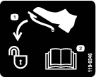
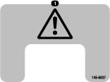
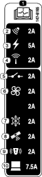
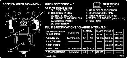
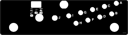
Safety and Instructional Decals
|
Safety decals and instructions are easily visible to the operator and are located near any area of potential danger. Replace any decal that is damaged or missing. |
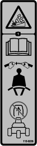


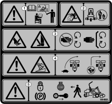
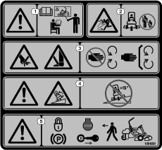
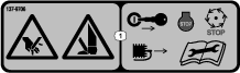


Refer to Definition of Terms for descriptions of the modes listed in decal 145-0345.
Setup
Installing the Cutting Units
Parts needed for this procedure:
| Cutting unit (order separately; contact your authorized Toro distributor) | 3 |
| Electric counterweight | 3 |
| Capscrew | 6 |
| O-ring | 3 |
-
Prepare the cutting units for installation; refer to your cutting unit Operator’s Manual.
-
Apply grease to the inside spline of the drive coupler.
-
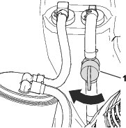
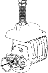
Install an O-ring to each reel motor as shown in Figure 3.
-
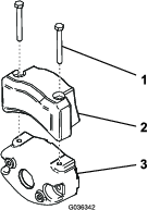
Secure the electrical counterweight to the existing counterweight with 2 capscrews as shown in Figure 4.
-
Install the cutting units; refer to Installing the Cutting Units.
Adjusting the Machine Settings
-
Connect the main-power connectors; refer to Main-Power Connectors.
-
Use the InfoCenter to adjust the machine settings; refer to Using the InfoCenter to Adjust the Machine Settings.
Installing the CE/UKCA Decals
If Required (CE/UKCA-Compliant Countries Only)
Parts needed for this procedure:
| Production year decal | 1 |
| CE warning decal (Part Number 139-8321) | 1 |
| CE/UKCA decal (Part Number 138-9470) | 1 |
If you use this machine in a country that complies to CE/UKCA standards, install the following decals:
Reducing the Tire Pressure
The tires are overinflated at the factory for shipping purposes. Reduce the pressure to the proper levels before starting the machine; refer to Checking the Tire Pressure.
Adding the Machine as a myTurf
-
Verify that all users of the machine have myTurf credentials; refer to the myTurf Software Guide.
-
Within myTurf, add the machine as an Asset; refer to the myTurf Software Guide.
Activating or Renewing a Cellular Service or RTK Plan
-
Technicians that have access to Toro materials can find instructions for activating or renewing a cellular service or RTK plan on the GeoLink Service Center.
Note: Both are required in order to operate the machine autonomously.
-
Search for the “GeoLink Activation Process” service bulletin.
-
Follow and complete the steps within the service bulletin.
Wait for Toro to send the cellular and RTK credentials before proceeding.
-
Insert and rotate the key to the ON position.
-
Connect to the machine using the GeoLink Mow supervisory app.
-
From the top menu bar, select the SETTINGS button.
-
Under Local Reference Point, set the coordinates and height of a local reference point that the machine will use for GNSS RTK localization.
Note: Use decimal degrees for the coordinates and meters for the height.
-
Under NTRIP Corrections, enter the information for the NTRIP caster.
-
Under Credentials, enter the information for the RTK subscription.
Confirming Cellular and RTK Connectivity
Note: It is recommended to perform this test onsite at the course where the machine will operate. This will give an accurate idea of the strength of the signal to the machine during normal operation.
-
Insert and rotate the key to the ON position.
-
Drive the machine to an outdoors area.
-
Connect to the machine using the GeoLink Mow supervisory app.
-
From the top menu bar, select the DIAGNOSTICS button.
-
Under Mobile network, confirm that there is a cellular connection to the machine.
-
Under Localization, confirm that there is a RTK connection to the machine.
Note: It may take a few minutes for the machine to connect to a cellular network or an RTK base station.
Validating the Object Detection System
Validate that the sensors for the object detection system are functioning properly before activating autonomous mode; refer to Verifying the Object Detection System.
Verifying the Autonomous Control System (ACS)
-
Insert and rotate the key to the ON position.
-
Drive the machine to an outdoors area.
-
Hold the autonomous/manual-mode switch to the left for 2 seconds to activate autonomous mode; refer to Autonomous/Manual-Mode Switch.
-
Connect to the machine using the GeoLink Mow supervisory app.
-
From the top menu bar, select the DIAGNOSTICS button.
-
Select the diagnostic fields to open up the detailed drop-down menus. Ensure that the ACS is working correctly.
Validating the GNSS and IMU Systems
-
Inspect the roof line of the machine for any bent antennas.
-
Insert and rotate the key to the ON position.
-
Drive the machine to a mowing area.
-
Set up a test CMA; refer to Mapping the Autonomous Operating Area and Mapping the Contiguous Mowing Area.
-
Create a mission for the mower to perform: for the first task, have it perform a clockwise cleanup pass on a fairway. Then, have it perform a counter-clockwise cleanup pass on the same fairway; refer to Creating a Mission and Creating a Custom Mowing Pattern
-
Run the mission; refer to Running a Mission.
-
Observe the machine during the mission and look for any inconsistent pathing between the clockwise and counter-clockwise passes.
Important: If differences are observed, it might be due to the antennas not being centered; contact technical support.
Product Overview
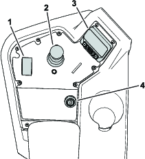
Key Switch
The key switch has 3 positions: OFF, ON, and START (Figure 9).
Use the key switch to start the engine, shut off the engine, or drive the machine without engine power; refer to Starting the Engine,Shutting Off the Engine, and Driving the Machine Without Engine Power.
Function-Control Switch
The function-control switch (Figure 8) provides 2 traction selections plus a NEUTRAL position.
-
NEUTRAL position—neutral and backlapping
-
MOW position—used for mowing operation
-
TRANSPORT position—used for transport operation
You can shift from MOW to TRANSPORT or TRANSPORT to MOW (not to NEUTRAL) while the machine is in motion; no damage will result
You can move the switch from TRANSPORT or MOW to NEUTRAL and the machine will come to a stop. If you try to switch from NEUTRAL to MOW or TRANSPORT while the pedal is not in the NEUTRAL position, an advisory occurs.
Lift/Lower Joystick
The lift/lower joystick (Figure 8) raises or lowers the cutting units. The joystick can engage or disengage the cutting-unit reels, depending on the function-control-switch position:
-
Function-control switch in the NEUTRAL position: The cutting units will raise or lower as long as you move the joystick forward or backward, but the reels will not engage unless the machine is in Backlap Mode.
-
Function-control switch in the MOW position: Move the joystick forward during your cutting operation to lower the cutting units and start the reels. Pull back on the joystick to stop the reels and raise the cutting units.
To stop the reels without raising the cutting units, pull back on the joystick momentarily and release it. Moving the joystick forward again will start the reels or pulling back again will lift the cutting units. You must engage this feature in the InfoCenter; refer to Adjusting the Tap-Off Delay.
-
Function-control switch in the TRANSPORT position: The cutting units can be raised, but the reels will not engage. An advisory appears in the InfoCenter if you attempt to lower the cutting units.
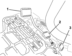
Traction Pedal
The traction pedal (Figure 10) has 3 functions: to make the machine move forward, to move it backward, and to stop the machine. Press the top of the pedal to move forward; press the bottom to move backward.
To stop the machine, allow the pedal to move to the NEUTRAL position. Do not rest the heel of your foot on the traction pedal in the REVERSE position while the machine is moving forward (Figure 11).

You can configure the maximum ground speed for manual mode operation as follows:
-
4.8 to 8 km/h (3 to 5 mph) forward mowing speed
-
8 to 16 km/h (5 to 10 mph) transport speed
-
3.2 to 8 km/h (2 to 5 mph) reverse speed
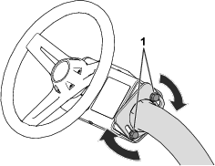
Steering-Arm-Locking Pedal
Press the pedal (Figure 10) and raise or lower the steering arm for operator comfort, then, release the pedal to lock the arm in place.
Brake Pedal
Press the brake pedal (Figure 12) to stop the machine.
Parking Brake
Use the parking brake (Figure 12) to prevent the machine from moving. To engage the parking brake, push down on the brake pedal and press the top forward to latch. To release the parking brake, press the brake pedal until the parking-brake latch retracts.
Autonomous Controls
Emergency-Stop (E-stop) Switch
In addition to the stop button in the supervisory app, another method of stopping the machine is to push down on the emergency-stop switch at the rear of the machine.
To disengage the emergency stop:
-
Pull the switch outward.
-
Reset the autonomous/manual-mode switch to enable autonomous mode.
Important: The E-stop switch only functions when the machine is operating in autonomous mode. Activating the E-stop switch does not affect a machine operating in manual mode.
Autonomous/Manual-Mode Switch
Press and hold the autonomous/manual-mode switch to the left for 2 seconds to engage AUTONOMOUS mode.
Press the switch to the right to engage MANUAL mode.
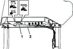
The autonomous status light indicates the current autonomous state of the machine:
-
Solid white—ACS turned on and in manual mode
-
Solid green—executing autonomous mode; do not approach
-
Blinking green—in autonomous mode, but object is near
-
Solid red—safe to approach; machine parked
GeoLink Mow Supervisory App
The GeoLink Mow Supervisory App is the tool used for setting up and operating a machine for autonomous mowing.
| Menu Bar Item | Description |
| HOME | The HOME menu is the first screen in the web app, and has shortcuts to the DASHBOARD, MISSIONS, MAP, and SETTINGS menus, as well as the terms of use and legal notices. |
| DASHBOARD | The DASHBOARD menu lists the current machine statuses and mission statuses. The control buttons at the bottom of the screen also control the machine remotely. |
| MISSIONS | The MISSIONS menu has areas for creating new missions as well as viewing current missions and mission history. Create custom mowing patterns within this menu. |
| MAP |
The MAP menu displays a map of your property and any mapped fairways. It also contains controls for mapping operational areas and other autonomous features. While the machine is operating, it can be used to monitor the machine during a mission. |
| SETTINGS | The SETTINGS menu allows you to change RTK settings and credentials, general operating settings, and personal preferences for the machine. |
| HELP |
The HELP menu allows you to access map data, machine logs, the operator’s manual, performance data, and software version information. |
| DIAGNOSTICS |
The DIAGNOSTICS menu lists the statuses of various parts of the machine, including hardware, sensors, and localization and connectivity information. This information can be used to troubleshoot issues with the machine, as it can quickly tell you which machine controls are active, disabled, or experiencing issues. |
| LOGOUT |
Log out of your myTurf account. |
| Menu Item | Description | |
| Local Reference Point | ||
| LATITUDE | Set the latitude of a local reference point that the machine uses for GNSS RTK localization. Use decimal degrees format. | |
| LONGITUDE | Set the longitude of a local reference point that the machine uses for GNSS RTK localization. Use decimal degrees format. | |
| HEIGHT | Set the height (in meters) of a local reference point that the machine uses for GNSS RTK localization. | |
| NTRIP Corrections | ||
| HOSTNAME | Set the connection name URL for the NTRIP (RTK) caster. | |
| PORT NUMBER | Set the port number for the caster. | |
| MOUNT POINT | Set a mount point name for the outgoing GNSS data stream from the caster. | |
| NMEA GGA Message | ||
| REQUIRED | Enables or disables NMEA GGA messages. Required is enabled by default. | |
| UPDATE PERIOD | Set the frequency of NMEA GGA messages. 5 seconds is the default setting. | |
| Credentials | ||
| USERNAME | Enter the username for the RTK subscription. | |
| PASSWORD | Enter the password for the RTK subscription. | |
| Map | ||
| LOCK MAP | Removes the ability to modify, delete, or create new mapped areas. | |
| Mowing | ||
| OVERLAP | Set the amount of overlap during mowing passes. | |
| Machine Speeds | ||
| MAIN MOWING SPEED | Set the maximum allowable speed of the machine during mowing. | |
| PERIMETER MOWING SPEED | Set the maximum allowable speed of the machine during clean-up passes. | |
| TRANSPORT SPEED | Set the maximum allowable speed of the machine when not mowing. | |
| Machine Info | ||
| FRIENDLY NAME | Set a name for the machine. It will be used in messages sent to the supervisor’s phone. | |
| User Info | ||
| LANGUAGE | Set the user interface language. | |
| UNITS | Set the units of measurement for the app. | |
| RESET SETTINGS TO FACTORY | Select to return to default factory settings. | |
Note: After changing the settings, select Save to save your settings, then key cycle the machine in order to enable the settings.
| Menu Item |
| MOBILE NETWORK > CARRIER NAME |
| MOBILE NETWORK > CONNECTION TYPE |
| MOBILE NETWORK > SIGNAL QUALITY |
| LOCALIZATION > GNSS STATUS |
| LOCALIZATION > GNSS ACCURACY |
| LOCALIZATION > VALID SATELLITES |
| LOCALIZATION > ROVER SATELLITES |
| LOCALIZATION > BASE SATELLITES |
| LOCALIZATION > RTK CONNECTION |
| LOCALIZATION > LOCALIZATION ACCURACY |
| EMERGENCY STOP |
| SENSORS > LIDAR DISTANCE |
| SENSORS > SONAR FRONT LEFT |
| SENSORS > SONAR REAR LEFT |
| SENSORS > SONAR REAR RIGHT |
| SENSORS > SONAR FRONT RIGHT |
| SENSORS > SONAR TOP LEFT |
| SENSORS > SONAR TOP RIGHT |
| SENSORS > RADAR FIELD NEAR |
Note: The machine may stop if the SIGNAL QUALITY or RTK CONNECTION fields display BAD. The machine doesn’t have a strong enough connection to the cellular network or the RTK base station in order to operate.
| Menu Item | Description | |
| Machine Status | ||
| STATE | Displays the current state of the machine. Refer to Machine State for a list of machine states. | |
| GNSS | Displays the quality of the GNSS signal. 90% or greater is good; 60% or less is poor. Use the DIAGNOSTICS menu and the LOCALIZATION list to help diagnose issues with GNSS/localization. | |
| SPEED | Displays the current speed of the machine. | |
| Mission Status | ||
| STATE | Displays the state of the current mission, mission progress, and time remaining to complete the mission. Refer to Mission State for a list of mission states. If a mission is not selected, the list will be blank. | |
| MISSION | Displays the ID number for the selected mission. | |
| FAIRWAYS | Displays the fairways in the queue for the current mission as well as a progress bar for each fairway. | |
| PATTERN | Displays the mowing pattern for the current mission. This may take up to 10 seconds to load. | |
| PROGRESS | Displays the progress percentage for the current mission. This may take up to 10 seconds to load. | |
| TIME REMAINING | Displays the estimated time until the mission is completed. | |
| CONTINUE | Button appears 10 minutes before the machine is scheduled to mow the next fairway in the mission. A text message is sent to the supervisor’s mobile device with a link to the DASHBOARD. Select the button, read the approval agreement, and select Accept to allow the machine to continue to the next fairway. | |
—Machine States
Refer to the following table for the meaning of the machine state display:
| Display | Meaning | Solution (if applicable) |
| Unknown | Unknown error | Key cycle the machine. Note: This may take up to 5 minutes. |
| Setup | The setup is occurring. | Wait and stand clear of the machine. |
| Idle | The machine is set to IDLE. | Set the mode to either MANUAL or AUTO. |
| Manual mode | The machine is set to MANUAL mode. | |
| Setup | The machine is set up for AUTO. | Press Go and accept the notice. |
| Awaiting notice | The app is waiting for you to accept the notice. | Press Go and accept the notice. |
| Calibrating | The machine is initiating autonomous mode. | Wait for at least 3 minutes and stand clear of the machine. |
| On standby | The machine is in autonomous mode and idling. | Plan a mission and press Go. |
| Executing | The machine is currently executing a mission. | |
| Going to sidestop | The machine is parking itself on the side. | |
| Going to pickup | The machine is going to the pick-up point. | |
| Going to point | The machine is going to a point the operator has selected on the map. | |
| Parked | The machine is in PARKED mode. |
Note: If the solution is to wait, waiting 30 seconds should be sufficient for the state to progress to another state. If not, key cycle the machine.
—Mission States
Refer to the following table for the meaning of the mission state display:
| Display | Meaning | Solution (if applicable) |
| Error | Unknown error | Key cycle the machine. Note: This may take up to 5 minutes. |
| Setup | Setting up | Wait. |
| Initializing | Initializing | Wait. |
| Loading | Loading missions | Wait. |
| Preparing | Loading missions | Wait. |
| Idle | No mission selected | Plan a mission and press Go. |
| Mowing | Mowing | |
| Paused | The mission is paused. | Press Go to resume the mission. |
| Canceled | The mission was canceled. | Create a mission. |
| Completed | The mission was completed. | Plan a new mission and press Go. |
| Waiting |
Note: If the solution is to wait, wait 3 minutes to allow the state to progress to another state. If it does not progress, key cycle the machine.
—Remote Machine Controls
The DASHBOARD screen has buttons for controlling the machine during a mission.

—Advisories and Faults, History Log
Diagnostic messages appear whenever the machine is undergoing an important action or encounters a fault.
Note: Filter messages according to the level of severity by selecting a severity level using the buttons in the top right.
| Icon | Meaning |
Info  | Advisory information about important actions. |
Issue  | There is an issue with the machine, but the machine will continue to operate. |
Error  | There is an issue with the machine that stops it from operating. |
| Display | Meaning | Solution (if applicable) |
| Canceled mission ## | Mission has been canceled by the operator. | Plan a new mission and press Go. |
| Canceling mission ## | Mission is being canceled by the operator. | Plan a new mission and press Go. |
| Completed mission ## | Mission is complete. | Plan a new mission and press Go. |
| Error in mission ## | Mission encountered an error and the machine is unable to operate. |
|
| Executing mission ## | Mission is being executed. | |
| Initializing mission ## | Mission is about to start. | |
| Loading mission ## | Mission is loading mission details. | |
| Pause mission ## | Mission was paused by the operator. | |
| Arrived at side stop point | Machine has arrived to the side stop point as ordered by the operator. | |
| Arrived at pickup point | Machine has arrived to the pickup point as ordered by the operator. | |
| System started | Machine key is in the ON position and the ACS system starts up. | |
| Arrived at specified point | Machine has arrived to the specified point chosen by the operator. | |
| Unable to prepare mission | Machine encountered an error while processing mission details. | |
| Difficult start position. | Machine is in a difficult start position. | |
| Preparing execution of mission ## | Mission is being processed. | |
| Map is empty | All map data is missing from the database. |
Menu
| Menu Item | Definition |
| MAP DATA |
Download, export, and import map files used on the machine. Export maps to other machines in a fleet, or, in order to reduce turf scrubbing, import additional maps with different transit paths to the machine; see Saving and Exporting Map Data. |
| LOGS |
Use this section to download logs from the machine. There are options to download complete logs or only the latest log report. You may also log a specific timeframe by using the Full Sample Logging controls. Note: It is not recommended to download these files while on a cellular connection since the files are large. |
| MANUAL |
Select this link to view the online Operator’s Manual. |
| ACS PERFORMANCE COUNTERS |
View data related to the performance and history of the autonomous machine. |
| SOFTWARE INFORMATION |
View software versions for the different autonomous systems. |
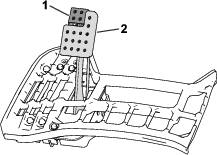
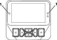
InfoCenter
Using the InfoCenter Display
The InfoCenter display (Figure 16) shows information about your machine, such as the operating status, various diagnostics, and other information about the machine.
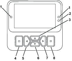
Note: The purpose of each button may change depending on what is required at the time. Each button is labeled with an icon displaying its current function.
Use the navigational buttons to navigate between several screens and menu items:
-
Splash screen: shows current machine information for a few seconds after you move the key to the ON position.
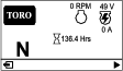
-
Main information screen (Figure 17): shows current machine information while the key is in the ON position.
-
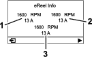
eReel motor screen (Figure 18): shows the speed and current of each cutting-unit motor.
-
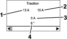
Traction motor screen (Figure 19): shows the current steering angle and the amperage allotted to each traction motor.
-
Main menu: refer to Understanding the InfoCenter Menu Items.
 | Hour meter |
 | Function-control switch is in the NEUTRAL position. |
 | Function-control switch is in the TRANSPORT position. |
 | Function-control switch is in the MOW position. |
 | The operator must sit in the seat when in manual mode. |
 | The parking brake is engaged. |
 | The electric parking brake is engaged. |
 | Start the engine. |
 | Engine |
 | The PTO is on. |
 | The PTO is disengaged. |
 | Battery |
 | Indicates when the cutting units are being raised. |
 | Indicates when the cutting units are being lowered. |
 | Active |
 | Inactive |
 | Previous |
 | Next |
 | Increase |
 | Decrease |
 | Previous screen |
 | Next screen |
 | Increase value |
 | Decrease value |
 | Menu |
 | Scroll up/down |
 | Scroll left/right |
Understanding the InfoCenter Menu Items
To access the main menu, press the back/exit button while at any of the information screens.
Refer to the following tables for a description of the options available from the menus:
| Menu Item | Description |
| FAULTS | The FAULTS menu contains a list of the recent machine faults. Refer to the Service Manual or your authorized Toro distributor for more information on the FAULTS menu. |
| SERVICE | The SERVICE menu contains information on the machine such as hours of use, counts, and calibration. You can also enable the cutting-unit backlap procedure. Refer to the Service table. |
| DIAGNOSTICS | The DIAGNOSTICS menu lists various states and data that the machine currently has. You can use this information to troubleshoot certain issues, as it quickly tells you which machine controls are on/off and lists control levels (e.g., sensor values). Refer to the Diagnostics table. |
| SETTINGS | The SETTINGS menu allows you to modify settings for the InfoCenter display. Refer to the Settings table. |
| MACHINE SETTINGS | The MACHINE SETTINGS menu allows you to adjust machine settings, such as reel speed, maximum mowing speed, and maximum transport speed. Refer to the Machine Settings table. |
| ABOUT | The ABOUT menu lists the model number, serial number, and software version of your machine. Refer to the About table. |
AUTONOMOUS | The AUTONOMOUS menu lists settings for testing the autonomous operation of the machine. |
| Menu Item | Description |
| HOURS | Lists the total number of hours that the key, engine, reels, and backlap have been on, as well as the next service due. |
| COUNTS | Lists the number of starts, mows, tap-offs, backlaps, and number of times that the engine was cranked longer than 30 seconds. |
| BACKLAP | Engages/disengages the cutting-unit backlap procedure (when you engage this procedure, you can disengage the mode with this setting or by moving the key to the OFF position). |
| CALIBRATION | Allows you to calibrate the steering system, traction system, and lift actuators. Refer to the Service Manual for more information on calibration. |
| Menu Item | Description |
| ENGINE | Indicates the inputs and outputs for starting the engine. |
| 48V ENABLE | Indicates the inputs and outputs for the 48V system. |
| GENERATOR | Indicates the inputs and outputs for the generator. |
| TRACTION | Indicates the inputs and outputs for the traction pedal. |
| STEERING | Indicates the inputs and outputs for the steering system. |
| LIFT/LOWER | Indicates the inputs and outputs for raising and lowering the cutting units. |
| PTO | Indicates the inputs and outputs for enabling the PTO circuit. |
| CAN STATISTICS | Indicates the inputs and outputs for the CAN. |
| 12V SYSTEM | Indicates the inputs and outputs for the 12V system. |
| AUTONOMOUS | Indicates the inputs and outputs for the autonomous system. |
| Menu Item | Description |
| ENTER PIN | Allows a person (superintendent/mechanic) authorized by your company with the PIN code to access protected menus. |
| BACKLIGHT | Controls the brightness of the LCD display. |
| LANGUAGE | Controls the language used on the InfoCenter. |
| FONT SIZE | Controls the size of the font on the InfoCenter. |
| UNITS | Controls the units used on the InfoCenter. The menu choices are English or metric. |
| PROTECT SETTINGS | Controls the protected menus. |
| RESET DEFAULTS | Resets the InfoCenter to default settings. |
| Menu Item | Description |
| TAPOFF TIME | Controls the tap-off delay. |
| REEL SPEED | Controls the blade speed on the cutting units. |
| LOWER SPEED | Sets the speed that the cutting units lower to the ground for mowing. |
| BACKLAP SPEED | Controls the backlap speed. |
| CLIP CONTROL | Turns the automatic clip-control feature on or off.. |
| BLADE COUNT | Set the number of blades in each reel. This setting is only necessary if CLIP CONTROL is set to ON. |
| HEIGHT OF CUT | Sets the desired height of cut. This setting is only necessary if CLIP CONTROL is set to ON. |
| MAX MOW | Sets the maximum machine speed while mowing. |
| MAX TRANSPORT | Sets the maximum machine speed while transporting. |
| MAX REVERSE | Sets the maximum machine speed while moving the machine in reverse. |
| SLOW & TURN | Enables or disables the slow in turn function. |
| 3WD KIT | Enables or disables the 3-Wheel Drive Kit. |
| Menu Item | Description |
| MODEL | Lists the model number of the machine. |
| SN | Lists the serial number of the machine. |
| S/W REV | Lists the software revision of the master controller. |
| S/W Rev ACS | Lists the software revision of the ACS. |
| XDM-2700 | Lists the software revision of the InfoCenter. |
| CUTTING UNIT 1 | Lists the software revision of the center cutting unit motor. |
| CUTTING UNIT 2 | Lists the software revision of the front, left cutting unit motor. |
| CUTTING UNIT 3 | List the software revision of the front, right cutting unit motor. |
| GENERATOR | Lists the serial number of the generator. |
| LIFT LOWER 1 | Lists the software part number and the revision version for the center cutting unit. |
| LIFT LOWER 2 | Lists the software part number and the revision version for the front left cutting unit. |
| LIFT LOWER 3 | Lists the software part number and the revision version for the front right cutting unit. |
| TRACTION1 | Lists the software part number and the revision version for the front right traction motor. |
| TRACTION2 | Lists the software part number and the revision version for the front left traction motor. |
| TRACTION3 | Lists the software part number and the revision version for the 3-Wheel Drive Kit (if equipped). |
| STEERING | Lists the software part number and the revision version for the rear steering motor. |
| Menu Item | Description |
| EMULATE MOWING | Autonomous behavior is followed, but the cutting units will not be engaged. |
| OVERRIDE ACS LOWER | Autonomous behavior is followed, but the cutting units will lower only to the extent allowed by LOWER LIMIT. |
| LOWER LIMIT | A percentage of the lower position commanded by the ACS. 85 is enough to observe that the cutting units will lower, but they will not hit the ground. |
Note: Protected
under Protected Menus—accessible only by entering PIN; refer
to Accessing Protected Menus.
Accessing Protected Menus
Note: The factory default PIN code for you machine is either 0000 or 1234.If you changed the PIN code and forgot the code, contact your authorized Toro distributor for assistance.
-
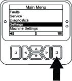
From the MAIN MENU, scroll down to the SETTINGS menu and press the select button (Figure 20).
-
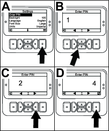
In the SETTINGS menu, scroll to ENTER PIN and press the select button (Figure 21A).
-
To enter the PIN code, press the up/down navigation buttons until the correct first digit appears, then press the right navigation button to move on to the next digit (Figure 21B and Figure 21C). Repeat this step until the last digit is entered.
-
Press the select button (Figure 21D).
Note: If the display accepts the PIN code and the protected menu is unlocked,
 displays in the upper right corner of the screen.
 -
To lock the protected menu, rotate the key switch to the OFF position and then to the ON position.
Viewing and Changing the Protected Menu Settings
-
In SETTINGS, scroll down to PROTECT SETTINGS.
-
To view and change the settings without entering a PIN code, use the select button to change the PROTECT SETTINGS to
 (Off).
 -
To view and change the settings with a PIN code, use the select button to change the PROTECT SETTINGS to
 (On),
set the PIN code, and turn the key in the ignition switch to the OFF position and then to the ON position.
(On),
set the PIN code, and turn the key in the ignition switch to the OFF position and then to the ON position.
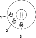
Understanding the Diagnostic Light
-
Flashing red—active fault
-
Solid red—active advisory
-
Solid blue—calibration/dialog messages
-
Solid green—normal operation
Standard Display Messages When Machine is not in Manual Mode
The #1 LEDs turn solid blue and the following messages may display when the machine is not in manual mode. Wait or follow the instructions on the display to operate the machine:
-
MACHINE NOT READY FOR AUTONOMOUS
-
ACS NOT READY, PLEASE WAIT
-
HOLD AUTONOMOUS ENGAGE FOR 2 SECONDS
-
AUTONOMOUS ACTIVE, LEAVE MACHINE AND USE THE APP
Advisories
Operator advisories automatically display on the InfoCenter screen or the supervisory app when a machine function requires additional action. For example, if you attempt to start the engine while pressing the traction pedal, an advisory displays, indicating that the traction pedal must be in the NEUTRAL position.
For each advisory that occurs, there is an advisory code (letter and number), an issue (first line of the message e.g., autonomous denied, autonomous abort), a cause (the cause of the advisory displayed), and a remedy (second line of text).
Note: Advisories are not recorded into the fault log.
Refer to the following table for all of the InfoCenter advisories:
Note: You can clear an advisory from the InfoCenter display screen by pressing any of the keys.
| Code | Issue | Cause | Remedy |
| B2900 | Autonomous Denied | Parking brake engaged | Disengage parking brake |
| B2901 | Autonomous Denied | Not in MOW | Move the function-control switch to MOW |
| B2902 | Autonomous Denied | An operator is in the seat | Leave the operator’s seat |
| B2903 | Autonomous Denied | The traction pedal is engaged | Return the traction pedal to the NEUTRAL position |
| B2904 | Autonomous Denied | Joystick switch engaged | Disengage joystick switch |
| B2905 | Autonomous Denied | There is steering wheel movement | Stop moving the steering wheel |
| B2906 | Autonomous Denied | Machine is not ready | Wait or address fault |
| B2907 | Autonomous Denied | ACS is not ready | Wait or address fault |
| B2908 | Autonomous Denied | Various | Consult the supervisory app |
| B2910 | Autonomous Abort | Operator aborted | Reset the autonomous/manual-mode switch |
| B2911 | Autonomous Abort | Fault(s) active | Machine service required. Resolve active fault(s) |
| B2912 | Autonomous Abort | Operator presence detected | Reset the autonomous/manual-mode switch |
| B2913 | Autonomous Abort | Object detected | Reset the autonomous/manual-mode switch |
| B2914 | Autonomous Abort | Various | Consult the supervisory app |
| B2940 | Autonomous Degraded | Various | Consult the supervisory app |
| B2950 | Autonomous Paused | Various | Consult the supervisory app |
Refer to the following table for all of the supervisory app advisories:
| Code | Issue | Cause | Remedy |
| B2908-1 | Autonomous operation denied | Machine is outside an AOA | Move the machine to an AOA |
| B2908-2 | Autonomous operation denied | Map is not valid |
|
| B2914-1 | Autonomous operation aborted | Maximum slope allowed was exceeded |
|
| B2914-2 | Autonomous operation aborted | Machine exited autonomous operation |
|
| B2914-3 | Autonomous operation aborted | IMU not healthy; unable to operate |
|
| B2914-4 | Autonomous operation aborted | Emergency Stop was triggered | Release the Emergency Stop button and reset autonomous operation |
| B2914-5 | Autonomous operation aborted | Sonar Front Left was triggered |
|
| B2914-6 | Autonomous operation aborted | Sonar Rear Left was triggered |
|
| B2914-7 | Autonomous operation aborted | Sonar Rear Right was triggered |
|
| B2914-8 | Autonomous operation aborted | Sonar Front Right was triggered |
|
| B2914-9 | Autonomous operation aborted | Radar field near was triggered |
|
| B2914-10 | Autonomous operation aborted | Sonar Top Left was triggered |
|
| B2914-11 | Autonomous operation aborted | Sonar Top Right was triggered |
|
| B2914-12 | Autonomous operation aborted | Autonomous/manual-mode switch is in manual mode |
Reset the autonomous/manual-mode switch |
| B2940-1 | Autonomous operation performance degraded | An obstacle near the machine is affecting operation |
|
| B2940-2 | Autonomous operation performance degraded | PC temperature is outside of operational limits | Performance may be degraded but the machine is fully operationalIf the problem persists, contact technical support |
| B2940-3 | Autonomous operation performance degraded | Wheels are slipping |
|
| B2940-4 | Autonomous operation performance degraded | IMU error is outside of operational limits | Performance may be degraded but the machine is fully operationalIf the problem persists, contact technical support |
| B2940-5 | Autonomous operation performance degraded | Distance to base station is outside of operational limits | Performance may be degraded but machine is fully operational |
| B2940-6 | Autonomous operation performance degraded | No connection to mobile network |
|
| B2940-7 | Autonomous operation performance degraded | LiDAR temperature is outside of operational limits |
|
| B2950-1 | Autonomous operation paused | Distance from current position to the last position of the machine is outside of operational limits |
|
| B2950-2 | Autonomous operation paused | Navigation error |
|
| B2950-3 | Autonomous operation paused | PC response time is outside of operational limits | Performance may be degraded but the machine is fully operationalIf the problem persists, contact technical support |
| B2950-4 | Autonomous operation paused | Base station signal quality is outside of operational limits |
|
| B2950-5 | Autonomous operation paused | Poor GNSS RTK quality |
|
| B2950-6 | Autonomous operation paused | Machine is connected to a base station different from the one used while mapping |
|
| B2950-7 | Autonomous operation paused | Position accuracy outside of operational limits |
|
| B2950-8 | Autonomous operation paused | Lift/Lower subsystem has a problem |
|
| B2950-9 | Autonomous operation paused | PTO subsystem has a problem |
|
| B2950-10 | Autonomous operation paused | Steering subsystem has a problem |
|
| B2950-11 | Autonomous operation paused | Traction subsystem has a problem |
|
| B2950-12 | Autonomous operation paused | Mission encountered an error while processing mission details |
|
| B2950-13 | Autonomous operation paused | Difficult start position |
Move the machine to an open area in order to speed up operation |
Main-Power Connectors
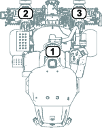
Before working on the machine or installing, removing, or working on the cutting units, disconnect the machine from the power supply by separating the main-power connectors (Figure 23), located at the base of the rollover bar on the left side of the traction unit. Plug the connectors together before operating the machine.
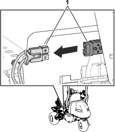
Caution
If you do not disconnect the power to the machine, someone could accidentally start the machine, causing serious bodily injury.
Always separate the connectors before working on the machine.
Fuel-Shutoff Valve
Refer to Figure 25 and the Specifications Table for dimensions and weight.
Note: Specifications and design are subject to change without notice.
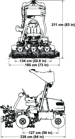
| Width of cut | 151 cm (59.5 inches) |
| Wheel track | 134 cm (52.8 inches) |
| Wheel base | 127 cm (50 inches) |
| Overall length | 239 cm (94 inches) |
| Overall width | 185 cm (73 inches) |
| Overall height | 211 cm (83 inches) |
| Weight* | 841 kg (1,855 lb) |
| *Traction unit equipped with 8-blade cutting units, no fuel, no operator, and with the Standard Seat equipped. | |
Attachments/Accessories
A selection of Toro approved attachments and accessories is available for use with the machine to enhance and expand its capabilities. Contact your Authorized Service Dealer or authorized Toro distributor or go to www.Toro.com or a list of all approved attachments and accessories.
To ensure optimum performance and continued safety certification of the machine, use only genuine Toro replacement parts and accessories. Replacement parts and accessories made by other manufacturers could be dangerous, and such use could void the product warranty.
Operation
Before Operation
Supervisor Information
Supervisor for Deployment and Operation of Machine(s)
-
The supervisor is responsible for inspecting the machine(s) prior to use to ensure that it is ready to operate reliably. Inspections include but are not limited to the following:
-
Verify that the sensors are functioning properly, clean of dust and debris, and are pointed in the proper direction prior to daily deployment.
-
Perform normal daily operation checklist(s) as required for the machine(s) prior to daily deployment. Acceptance is in the app.
-
The machine does not operate autonomously until the supervisor accepts the criteria listed in the supervisory app agreement.
-
Perform any additional maintenance or readiness checks as detailed in the training or instructions provided by the machine(s).
-
Carry the mobile device connected to the machine via the autonomous control app at all times.
-
-
The supervisor is responsible for ensuring that all hazards have been mapped prior to autonomous operation. The operating areas must follow the requirements in Mapping Requirements.
-
The supervisor is responsible for initiating autonomous operation of the machine(s) from a staging area within the autonomous operating area. The machine must be transported to that staging area and back to the storage area in manual mode by a qualified operator.
-
Prior to and during machine operation, the supervisor is responsible for inspecting the operating areas (including but not limited to the autonomous operation area); the contiguous mowing area; and the transit paths to identify and remove hazards including but not limited to the following:
-
Items in the operating area such as sticks, rocks, debris, golf equipment, raised sprinklers, and any other objects not meant to be cut by blades or otherwise mowed
-
Bystanders and children
-
Unmowable areas such as areas under repair, standing water, damaged turf, etc.
-
-
A qualified manual operator may need to mow with the machine in manual mode if operating that machine autonomously is restricted by, but not limited to, the following:
-
Inadequate wireless signal (i.e., cellular, GNSS connectivity, etc.)
-
Inadequate GNSS accuracy and/or RTK correction
-
Restriction of operating area for the machine(s) based on and identified by the site assessment
-
Area too close to AOA boundary or immovable obstacles
-
Supervisor's Daily Pre-Deployment Checklist
Prior to deploying the mower for autonomous operation, the following statements must be true:
Qualifications of the Machine Supervisor
I am a trained and Toro-approved autonomous mower supervisor.
Machine Function
-
I have verified within the last 12 hours that all object detection sensors are securely mounted on the machine, functioning properly, and are positioned in the proper direction.
Note: To verify that the sensors are functioning properly, read and complete the steps in Verifying the Object Detection System.
-
Ensure that the machine is on.
-
Ensure that the supervisory app is connected to the machine.
-
Go to the DIAGNOSTICS page.
-
Expand theSensors list.
-
Walk around the machine and ensure that each light turns red. Disregard the front, top sensors as those are used for drop-off detection.
-
-
I have verified that the cutting reels are in good mowing condition and are free from debris and blockages; refer to Cutting Unit Maintenance.
Site Pre-Inspection
I have inspected all fairways to be autonomously mowed and therefore verify the following:
-
The operating area is free from all debris that could interfere with the operation of the machine or that the machine could throw.
-
Standing water, tree limbs, non-turf objects, holes, or washouts, etc. have been either repaired or removed.
-
All irrigation heads are completely retracted to the ground.
-
All expected obstacles have been removed from the autonomous operating area, including bunker rakes, course markers, signs, rope fences, moveable cart markers, posts, and stakes.
-
-
Bystanders and children are out of the autonomous operating area.
Immediately after Launching the Machine
I will verify that all audible and visual warnings on the machine are functioning properly:
-
Prior to the machine moving, a buzzer will make a warning noise for 2 seconds.
-
While running in autonomous mode, the amber lights at the front and rear of the machine will be continually flashing. The autonomous status light will be green.
If the machine does not function properly, I will stop it immediately and correct the problem(s) before resuming operation.
If you have issues or concerns about any of the items in this checklist, read the Operator’s Manual.
Fuel Specification
Fuel tank capacity: 18.5 L (4.9 US gallons)
Recommended Fuel: Unleaded gasoline with an octane rating of 87 or higher ((R+M)/2 rating method)
Ethanol: Gasoline with up to 10% ethanol (gasohol) or 15% MTBE (methyl tertiary butyl ether) by volume is acceptable. Ethanol and MTBE are not the same. Gasoline with 15% ethanol (E15) by volume is not approved for use.
-
Never use gasoline that contains more than 10% ethanol by volume, such as E15 (contains 15% ethanol), E20 (contains 20% ethanol), or E85 (contains up to 85% ethanol).
-
Do not use fuel that contains methanol.
-
Do not store fuel either in the fuel tank or fuel containers over the winter, unless you use a fuel stabilizer.
-
Do not add oil to gasoline.
-
For best results, use only clean, fresh (less than 30 days old) fuel.
-
Using unapproved gasoline may cause performance problems and/or engine damage, which may not be covered under the warranty.
Important: Do not use fuel additives other than a fuel stabilizer/conditioner. Do not use fuel stabilizers with an alcohol base such as ethanol, methanol, or isopropanol.
Filling the Fuel Tank
-
Engage the parking brake, shut off the engine, remove the key, and wait for all movement to stop.
-
Clean around the fuel-tank cap and remove it (Figure 26).
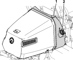
-
Add the specified fuel to the fuel tank until the level is 25 mm (1 inch) below the bottom of the filler neck. This space in the tank allows the fuel to expand.
Important: Do not fill the fuel tank completely full.
-
Install the cap.
Note: You will hear a click sound when the cap is secure.
-
Wipe up any spilled fuel.
Identifying the Cutting Units
Using the InfoCenter to Adjust the Machine Settings
You can use the InfoCenter to adjust the following machine settings:
-
Tap-off delay; refer to Adjusting the Tap-Off Delay.
-
Reel speed while mowing; refer to Adjusting the Mowing Reel Speed.
-
Reel speed while backlapping the cutting units; refer to Adjusting the Backlap Reel Speed.
-
Clip control; refer to Adjusting the Clip-Control Feature.
-
Height of cut (HOC); refer to Adjusting the Height of Cut (HOC).
-
Number of cutting-unit blades; refer to Adjusting the Number of Cutting-Unit Blades.
-
Maximum mowing speed; refer to Adjusting the Maximum Mowing Speed.
-
Cutting-unit lower speed; refer to Setting the Cutting-Unit Lower Speed.
-
Maximum transport speed; refer to Adjusting the Maximum Transport Speed.
-
Maximum reverse speed; refer to Adjusting the Maximum Reverse Speed.
-
Slow in turn; refer to Setting the Slow in Turn Function.
-
Disabling an equipped 3-Wheel-Drive Kit; refer to Disabling an Equipped 3-Wheel-Drive Kit.
Note: Each setting is passcode-protected. You may need to enter a passcode to edit the settings.
Adjusting the Tap-Off Delay
Navigate to the TAPOFF TIME option to adjust the tap-off delay. The tap-off delay feature allows the cutting units to turn off without raising. The delay setting represents the maximum time for the lift/lower joystick to remain in the rearward position to activate this feature.
Refer to the following table for the delay time options and their corresponding increment numbers:
| Increment Number | Delay Time (Seconds) |
| 1 | Off |
| 2 | 0.050 |
| 3 | 0.100 |
| 4 | 0.150 |
| 5 | 0.200 |
| 6 | 0.250 |
| 7 | 0.300 |
| 8 | 0.350 |
| 9 | 0.400 |
| 10 | 0.450 |
Note: The factory default setting is 1, which disables this feature.
Adjusting the Mowing Reel Speed
Navigate to the REEL SPEED option to adjust the reel speed while mowing. This setting can be adjusted when the clip control setting is OFF; refer to Setting the Clip-Control Feature.
Refer to the following table for the reel speed options and their corresponding increment numbers:
| Increment Number | Reel Speed (RPM) |
| 1 | 800 |
| 2 | 950 |
| 3 | 1100 |
| 4 | 1250 |
| 5 | 1400 |
| 6 | 1550 |
| 7 | 1700 |
| 8 | 1850 |
| 9 | 2000 |
Note: The factory default setting is 1550 rpm (increment number 6).
Setting the Cutting-Unit Lower Speed
Navigate to the LOWER SPEED option to set the speed that the cutting units lower to the ground for mowing. You can toggle between 1 (slowest speed) and 9 (quickest speed).
Test the lower speed before you mow. Adjust the speed as desired.
Note: The factory default setting is 5.
Adjusting the Backlap Reel Speed
Navigate to the BACKLAP RPM option to adjust the reel speed while performing a backlap operation.
Refer to the following table for the reel speed options and their corresponding increment numbers:
| Increment Number | Reel Speed (RPM) |
| 1 | 200 |
| 2 | 240 |
| 3 | 280 |
| 4 | 320 |
| 5 | 360 |
| 6 | 400 |
| 7 | 440 |
| 8 | 480 |
| 9 | 520 |
Note: The factory default setting is 200 rpm (increment number 1).
Adjusting the Clip-Control Feature
Understanding the Radius-Dependent-Speed (RDS) System
To achieve a consistent, high quality-of-cut and a uniform after cut appearance, the machine is equipped with the patent-pending Radius Dependent Speed™ (RDS) system. The RDS system is a clip-control and independent wheel-speed feature that varies the speeds of each reel motor and each traction motor to maintain a constant clip and reduce turf scrubbing in turns while cutting.
When the machine is turning while cutting (e.g., during the clean-up pass), the reel on the inside of the turn will rotate at a slower rpm than the reel on the outside of the turn. The center reel splits the difference of the inside and outside reel speeds so that all three cutting units have the same clip. The sharper the turn, the greater the difference in reel speeds. Additionally, if the machine speed changes while you are cutting, the RDS system adjusts the reel speed to maintain a constant clip. This feature reduces turf thinning on the inside reel (in comparison to other riding fairway mowers), which virtually eliminates triplex ring.
The RDS system also adjusts each wheel-motor speed during a turn, similar to the reel-motor speeds changing in a turn. The inside wheel motor will turn at a slower rpm than the outside wheel motor. This minimizes wheel scrubbing in the turn and can reduce triplex ring.
Setting the Clip-Control Feature
Navigate to the CLIP CONTROL option to set the RDS system feature.
-
Clip control set to ON: The machine uses your settings from the HEIGHT OF CUT (HOC) and BLADE COUNT options and the left and right wheel speeds to determine the speed of each reel.
-
Clip control set to OFF: The machine uses your setting from the REEL SPEED option.
Note: The factory default setting is ON.
Adjusting the Height of Cut (HOC)
Navigate to the HEIGHT OF CUT (HOC) option to adjust the height of cut. The clip control feature must be set to ON to use this feature; refer to Setting the Clip-Control Feature.
Note: The factory default setting is 12.7 mm (0.5 inch).
Adjusting the Number of Cutting-Unit Blades
Navigate to the BLADE COUNT option to adjust the number of cutting-unit blades. Determine the number of blades in your equipped cutting units, and select the appropriate value (5, 8, 11, or 14).
Note: The factory default setting is 8.
Adjusting the Maximum Mowing Speed
Navigate to the MAX MOW option to adjust the maximum mowing speed. You can adjust the speed from 4.8 km/h (3.0 mph) to 8.0 km/h (5.0 mph) in increments of 0.3 km/h (0.2 mph).
Note: The factory default setting is 6.1 km/h (3.8 mph).
Adjusting the Maximum Transport Speed
Navigate to the MAX TRANSPORT option to adjust the maximum transport speed. You can adjust the speed from 8.0 km/h (5.0 mph) to 16.0 km/h (10.0 mph) in increments of 0.8 km/h (0.5 mph).
Note: The factory default setting is 16.0 km/h (10.0 mph).
Adjusting the Maximum Reverse Speed
Navigate to the MAX REVERSE option to adjust the maximum reverse speed. You can adjust the speed from 3.2 km/h (2.0 mph) to 8.0 km/h (5.0 mph) in increments of 0.8 km/h (0.5 mph).
Note: The factory default setting is 4.0 km/h (2.5 mph).
Note: For machine-software versions A through D, the maximum speed is 4.8 km/h (3.0 mph). Update the machine software for the capability to set the maximum speed to 8.0 km/h (5.0 mph).
Setting the Slow in Turn Function
Navigate to the SLOW & TURN option to set the slow in turn function. The slow in turn function decreases the machine speed while you turn the machine for another cutting pass on the green.
Note: The factory default setting is OFF.
Disabling an Equipped 3-Wheel-Drive Kit
Navigate to the 3WD KIT option to disable an equipped 3-Wheel-Drive Kit.
Note: When you install the 3-Wheel-Drive Kit, the kit is automatically enabled.
Understanding the InfoCenter Dialog Messages
When the machine is being calibrated, dialog messages appear in the InfoCenter. These messages are intended to instruct you through the calibration process.
Refer to the following table for a list of each dialog message:
| Message Number | InfoCenter Message Text |
| 1 | Return pedal to neutral |
| 4 | Move pedal to max forward and hold |
| 5 | Max forward calibration passed |
| 9 | Max forward calibration failed. Voltage out of spec |
| 13 | Move pedal to max reverse and hold |
| 14 | Max reverse calibration passed |
| 16 | Max reverse calibration failed. Voltage out of spec |
| 17 | Calibration failed. Pedal position unknown |
| 18 | Return pedal to neutral. Continue? |
| 100 | Calibration is engaged |
| 101 | Calibration is complete |
| 102 | Cycle the key switch |
| 110 | Inhibit calibration. Component not responding |
| 111 | Inhibit calibration. Component not ready |
| 112 | Inhibit calibration. Fault active |
| 113 | Inhibit calibration. Not in seat |
| 114 | Inhibit calibration. Not in neutral |
| 115 | Inhibit calibration. In neutral |
| 116 | Inhibit calibration. Parking brake is engaged |
| 300 | Return pedal to neutral |
| 301 | Center steering wheel. Continue? |
| 302 | Manually center rear wheel. Continue? |
| 303 | Steer rear wheel max left. Continue? |
| 304 | Steer rear wheel max right. Continue? |
| 305 | Rear wheel center out of range |
| 306 | Rear wheel angle out of range |
| 400 | Caution: Machine must be on jack stands. Continue? |
| 401 | Inhibit calibration. Contactor open |
| 402 | Inhibit calibration. Pedal in Neutral |
| 403 | Return pedal to neutral |
| 404 | Wait for wheels to stop |
| 405 | Move pedal to max forward and hold |
| 406 | Calibration active. Hold pedal |
| 500 | Lift/Lower extend active |
| 501 | Lift/Lower retract active |
| 502 | Move joystick to lower position |
| 503 | Move joystick to raise position |
| 504 | Is the cutting unit installed? Continue? |
| 1100 | Traction diagnostic messages enabled |
| 1101 | Steering diagnostic messages enabled |
| 1102 | Safety diagnostic messages enabled |
Tilting the Steering Wheel
You can tilt the steering wheel to a comfortable operating position.
Performing Daily Maintenance
Before starting the machine each day, perform the following procedures:
-
Check the engine-oil level; refer to Checking the Engine Oil.
-
Check the reel-to-bedknife contact; refer to Checking the Reel-to-Bedknife Contact.
-
Check the tire pressure; refer to Checking the Tire Pressure.
-
Check the safety-interlock system; refer to Understanding the Safety-Interlock System.
-
Check the fuel level and add more fuel if needed; refer to Filling the Fuel Tank.
-
Check the parking brake function by actuating the parking brake and ensuring that it engages; refer to Parking Brake.
-
Inspect and clean the sensors (as required); refer to Inspecting the Sensors and Sensor BracketsCleaning the Sensors.
During Operation
Breaking in the Machine
Refer to the engine Owner’s Manual supplied with the machine for oil change and maintenance procedures recommended during the break-in period.
Only 8 hours of operation is required for the break-in period.
Since the first hours of operation are critical to future dependability of the machine, monitor its functions and performance closely so that minor difficulties, which could lead to major problems, are noted and can be corrected. Inspect the machine frequently during break-in for signs of oil leakage, loose fasteners, or any other malfunction.
Starting the Engine
Note: Inspect the areas beneath the cutting units to ensure that they are clear of debris.
-
Insert and rotate the key to the ON position.
-
Wait until the splash screen appears on the InfoCenter, then move the key to the START position until the engine starts.
-
Once the engine starts, remove your hand from the key; the key will automatically move to the ON position.
Note: A fault occurs if the engine cranks longer than 30 seconds.
Checking the Machine after Starting the Engine
-
Sit in the operator’s seat and fasten the seatbelt.
-
Move the function-control switch to the MOW position.
-
Disengage the parking brake.
-
Move the lift/lower joystick forward momentarily.
The cutting units should lower and all the reels should rotate.
-
Move the lift/lower joystick rearward.
The cutting reels should stop rotating and the cutting units should raise to the full transport position.
Shutting Off the Engine
-
Transport the machine to a level surface.
-
Move the function-control switch to the NEUTRAL position.
-
Engage the parking brake.
-
Rotate the key to the OFF position to shut off the engine.
-
Remove the key.
Understanding the Safety-Interlock System
| Maintenance Service Interval | Maintenance Procedure |
|---|---|
| Before each use or daily |
|
Caution
If the safety interlock switches are disconnected or damaged the machine could operate unexpectedly, causing personal injury.
-
Do not tamper with the interlock switches.
-
Check the operation of the interlock switches daily and replace any damaged switches before operating the machine.
The purpose of the safety-interlock system is to prevent operation of the machine where there is possible injury to you or damage to the machine.
The safety-interlock system prevents the machine from moving unless:
-
The parking brake is disengaged.
-
You are seated in the operator's seat (unless the machine is operating in autonomous mode).
-
The function-control switch is in the MOW position or the TRANSPORT position.
Additionally, the safety-interlock system prevents the reels from operating unless the function-control switch is in the MOW position (except when the machine is in Backlap Mode).
Checking the Safety-Interlock System
Engage manual mode and perform the following steps to check the interlock system:
-
Rise from the seat, start the engine, disengage the parking brake, move the function-control switch to the MOW or TRANSPORT position, and engage the traction pedal.
The machine should not move, as you are not in the seat. This indicates that the interlock system is operating correctly. Correct the problem if it is not operating properly.
-
Sit in the seat, start the engine, engage the parking brake, move the function-control switch to the MOW or TRANSPORT position, and engage the traction pedal.
The machine should not move, as the parking brake is engaged. This indicates that the interlock system is operating correctly. Correct the problem if it is not operating properly.
-
Sit in the seat, start the engine, disengage the parking brake, move the function-control switch to the NEUTRAL position, and engage the traction pedal.
The machine should not move, as the function-control switch is in the NEUTRAL position. This indicates that the interlock system is operating correctly. Correct the problem if it is not operating properly.
-
Sit on the seat, move the traction pedal to the NEUTRAL position, move the function-control switch to the NEUTRAL position, engage the parking brake, start the engine, and move the lift/lower joystick forward to lower the cutting units.
The cutting units should lower but not start rotating. If they start rotating, the interlock system is not operating correctly; correct the problem before operating the machine.
Driving the Machine without Mowing
-
Ensure that the cutting units are fully raised.
-
Sit in the seat, disengage the parking brake, and move the function-control switch to the TRANSPORT position to drive the machine without mowing.
-
Always approach rough areas at a reduced speed and cross severe undulations carefully.
-
Familiarize yourself with the width of the machine. Do not attempt to pass between objects that are close together to prevent costly damage and downtime.
Connecting to the Machine
Connecting to the machine via the Geolink Mow supervisory app allows you to program, monitor, and remotely control the machine.
-
Enter the serial number of your machine into the URL to connect to the machine.
The format for the URL is tacs
.geolink.solutions. -
Log in to the GeoLink Mow supervisory app using your myTurf credentials.
Note: If you cannot connect to the machine, ensure that the machine has been added to your club’s inventory as an asset; refer to the myTurf Software Guide.
Mapping the Fairway for Autonomous Operation
Mapping Requirements
Note: Refer to Understanding the Map Menu for an overview of mapping features.
-
The AOA boundary should not be mapped under trees or other obstacles as this could inhibit GNSS communication with the machine (Figure 29).
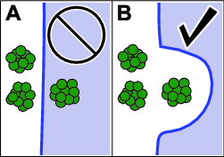
-
AOAs and CMAs must be mapped in a clockwise manner. For Holes and NOAs, map in a counter-clockwise manner.
-
Whenever mapping AOA or CMA boundaries, start and end the boundary on a straight line.
-
Ensure that the machine has a strong GNSS signal before starting any mapping process; refer to the Accuracy status box on the MAP page or in the Diagnostics Menu.
-
While mapping or just prior to mapping, the machine should not be operated in reverse. Carefully plan your mapping route before performing any mapping.
| Point-to-point | Minimum Distance |
| Distance between a CMA and an AOA or a NOA | 1.5 m (5 ft) |
| CMA width | 4.5 m (15 ft) |
Note: For best performance, the recommended distance between an AOA and a CMA is 5 m (16.4 ft), as this gives the machine enough space to perform efficient turns, therefore completing missions faster.
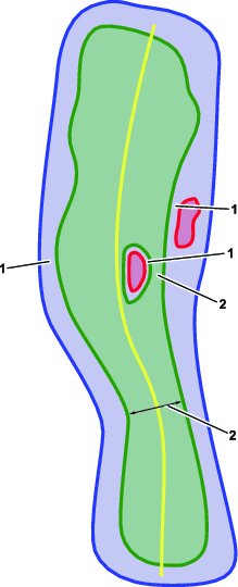
Mapping Process Overview
Follow the steps below to map your course for autonomous mowing:
-
Map the autonomous operating area (AOA); refer to Mapping the Autonomous Operating Area.
-
Map the contiguous mowing area (CMA); refer to Mapping the Contiguous Mowing Area.
-
Map non-operating areas (NOAs, Holes, and Poles); refer to Mapping Non-Operating Areas and Creating Poles.
-
Map transit paths; refer to Mapping Transit Paths.
-
Create pickup points; refer to Creating Pickup Points.
Mapping the Autonomous Operating Area
Prior to deploying the mower for autonomous mode operation, you must program the boundaries of the autonomous operating area (AOA) by mapping.
Important: Prior to mapping, inspect the property and make a note of any obstacles so that the autonomous operating area does not contain any obstacles or is too near any obstacles. The autonomous operating area must not contain any obstacles that the machine cannot detect, could damage the machine, or could create a safety hazard.It is the supervisor’s responsibility to ensure that all objects or obstructions are properly mapped outside of the autonomous operating area; refer to Mapping Non-Operating Areas and Creating Poles.If there is an obstruction (e.g., a solid wall or impassable terrain) between the machine and any of the hazards listed in Autonomous Operating Area Site Safety Criteria, ensure that the boundary of the AOA is set at least 2 m (7 ft) away from the obstruction.
Note: It is recommended to designate one of your machines as the primary mapping machine for the entire course. This would be the only machine in your fleet that creates new mapped areas or modifies existing mapped areas. The other machines in the fleet would use the map file created by the primary mapping machine.It is the supervisor’s responsibility to ensure that the correct map file is loaded onto every machine in a fleet.
-
Connect to the machine using the GeoLink Mow supervisory app.
-
From the home screen, press the menu button in the top-right corner and select MAP.
-
Drive the machine to where you would like to begin mapping your AOA.
Note: Pay attention to the color of the status boxes in the bottom-right of the screen: Accuracy and Clearance. If the color is red, it means the machine has poor localization accuracy or is detecting a nearby object. The machine cannot map in this area, so move the machine to a different starting location and try again.
Note: It is recommended to begin mapping your AOA in an area with recognizable markers, such as irrigation flags or other terrain features.
-
Select AOA from the sidebar menu or the expandable red button, followed by Perimeter.
-
Using the front-left corner of the left cutting unit as your marker, start by driving the machine in a straight line, and then map the perimeter of the AOA in a clockwise manner.
While mapping, pay attention to the color status boxes in the bottom-right of the screen: Speed, Accuracy, and Clearance. If the color is yellow or red, it means the machine is moving too quickly, has poor localization accuracy, or is detecting a nearby object. Slow down the machine, stop and wait, or move to a different location and try mapping again.
-
Green means the machine is within the ideal mapping parameters.
-
Yellow means the machine is approaching the mapping parameter limits.
-
Red means the machine potentially did not capture the boundary, has poor localization accuracy, or is detecting a nearby object.
-
-
Once you are near the beginning of your AOA line, slow down the machine and select Save.
-
Select Yes in the dialog box.
-
Select the Save button to save the boundary.
-
Refresh the map to view the completed AOA.
-
Look for any mapping errors and address as needed.
Mapping the Contiguous Mowing Area
-
Drive the machine to an area within the AOA where you would like to begin mapping your Contiguous Mowing Area (CMA).
Note: For optimal performance, the CMA boundary should be at least 5 m (16.4 ft) away from the AOA boundary. This will lead to good turning efficiency during autonomous operation. Refer to Mapping Requirements for the minimum distance requirements, but expect lower turning efficiency and longer mission times.
-
Select the red button in the bottom-right corner of the screen.
-
Select CMA from the menu followed by Perimeter.
-
Using the front-left corner of the left cutting unit as your marker, start by driving the machine in a straight line, and then map the perimeter of the CMA in a clockwise manner.
Note: Pay attention to the color status boxes in the bottom-right of the screen: Speed, Accuracy, and Clearance. If the color is yellow or red, it means the machine is moving too quickly, has poor localization accuracy, or is detecting a nearby object. Slow down the machine, stop and wait, or move to a different location and try mapping again.
-
Green means the machine is within the ideal mapping parameters.
-
Yellow means the machine is approaching the mapping parameter limits.
-
Red means the machine potentially did not capture the boundary, has poor localization accuracy, or is detecting a nearby object.
-
-
Once you are near the beginning of your CMA line, slow down the machine and select Save.
-
Select Yes in the dialog box.
-
Select the Save button to save the boundary.
-
Map the fairway D.O.P (direction of play):
-
Drive the machine to a starting point anywhere within the CMA.
-
Select D.O.P and drive the mower 5 m (16.4 ft) in the direction of play.
-
Select Save.
-
-
Map the Centerline:
-
Drive the machine to a point that is 1 m (3.3 ft) away from the CMA boundary at either end of the fairway.
-
Select Centerline and drive the machine down the center of the fairway.
Note: Ensure that the centerline extends 1 m (3.3 ft) outside of the CMA at both ends of the fairway.
-
After the machine has passed the other end of the CMA, select Save.
-
-
To create an area that the machine can transit but will not mow, select Hole, drive counter-clockwise around the area, and select Save.
-
Select Save again to save your CMA.
-
Look for any mapping errors and address as needed.
Select the error to view additional information about the error and the location of the error.
Mapping Non-Operating Areas
Important: Non-operating areas should be used for mapping large objects or obstructions, such as trees, bunkers, irrigation boxes, overhead obstacles, etc., or smaller obstacles that the machine cannot detect, such as wires, found in the AOA. It is the supervisor’s responsibility to ensure that all objects or obstructions have been mapped prior to autonomous operation. Follow the requirements in Mapping Requirements.NOAs cannot be mapped directly within a CMA; create a Hole within the CMA first before mapping the NOA.
-
To create an area inside of a Hole within a CMA that the machine will never transit, drive to the Hole, select NOA, drive counter-clockwise around the area, and select Save.
-
To create an area inside of an AOA but outside of the CMA that the machine will never transit, drive to the area outside of the CMA, select NOA, drive counter-clockwise around the area, and select Save.
Creating Poles
Important: Poles are small diameter (1 m or 3.3 ft) NOAs that prevent the machine from transiting through AOA areas that contain a small object, such as posts, drains, or irrigation boxes. Multiple poles can be created close to each other to form a barrier.
-
From the MAP menu, select Pole.
-
Once the front-left corner of the left cutting unit is near the obstacle you would like to map, select Point and Save.
A red circle representing the Pole will appear on your map.
Mapping Transit Paths
Transit paths are paths that the mower follows when moving between operating areas. The transit paths need to be a minimum of 3.5 m (11.5 ft) wide.
-
Drive the machine to a point inside of an AOA where you would like the transit path to start.
Note: Transit paths can start anywhere inside of an AOA, including inside of a CMA, but for best performance it is recommended to start the path near the AOA boundary.
-
From the MAP menu, select Path.
-
When you are ready to map, select Path and drive the exact route you would like the machine to follow between 2 AOAs.
-
After the machine is inside the other AOA and you are satisfied with the path, select Save.
An orange line representing the transit path will appear on your map.
Creating Pickup Points
Pickup points are areas inside of AOAs where the operator leaves/picks up the machine at any time during mowing. AOAs can be created specifically for pickup points and connected to a fairway using transit paths. From the supervisory app, the operator can instruct the machine to return to this point at any time.
-
Drive the machine to an area inside of an AOA where you would like to create a pickup point.
-
Select Pickup, Point, and Save.
The pickup point will be created at the position of the front-left corner of the left cutting unit.
Understanding the
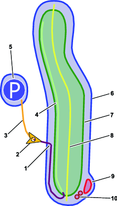
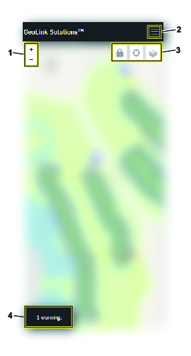
Changing Map Layers
-
From the MAP menu, select the Map Layers button.
The options Summary, Accuracy, and Object Detection appear.
Layer Description Summary Displays operating areas, transit paths, pick-up points, and poles. Also displays significant accuracy and object detection issues. Accuracy Displays GNSS and RTK accuracy for the mapped areas. Object Detection Displays if the machine has detected nearby objects in the mapped areas. -
Select the map layer you would like to view.
Modifying a Map After Mapping
From the MAP menu, select any point on the CMA portion of a fairway to open up the Fairway and the Properties, Centerline, and Holes windows.
Changing Fairway Names or Direction-of-Play
-
In the Properties window, change the name of the fairway or the direction-of-play angle.
-
Select Save.
Smoothing or Removing a CMA Centerline
Use the Smooth feature to give the center stripe in a Tuxedo-style cut a better appearance. To adjust the path of the centerline, remove the centerline and create a new one.
In the Centerline window, select Smooth or Remove.
Removing Mapped Areas of a Fairway
In the Fairway window, delete any mapped features by selecting the trashcan icon next to them.
Note: Ensure that these areas are mapped again and any errors are addressed before beginning a mission.
Modifying Hole Features
-
In the Holes window, view or delete any mapped Holes.
-
Select +Add to create a Hole.
Operating the Machine in Autonomous Mode
Creating a Mission
A mission is a sequence of fairway tasks. After the machine completes a mission, it will immediately start on the next mission. If no more missions exist, it will move to the side of the final fairway, unless instructed to move somewhere else by the operator.
-
Connect to the machine using the GeoLink Mow supervisory app.
-
From the home screen, select the MISSIONS button.
-
Select the + New mission button.
-
Select the fairway(s) that you want mowed from your list of mapped CMAs.
Note: Select the fairways in the order in which you want the fairways mowed.
Note: Ensure that all CMAs in a mission are connected via AOAs or transit paths.
-
Select a mowing pattern from Favorites or create a new mowing pattern within Custom.
-
Enter a supervisor’s phone number and select Save button.
Note: This allows the machine to send text message alerts if it is stopped and requires manual interaction from the supervisor.
-
Select Save.
If the mower is idle during this step, the mower begins the mission.
Note: After you save a mission, the mission will appear under MISSIONS.
Creating a Custom Mowing Pattern
-
Select the MISSIONS button.
-
After selecting New mission, select Custom under the section titled Mowing Pattern Selection.
Three pattern options appear: Stripes, Tuxedo, or Cleanup.
-
The options for Stripes are:
Option Definition Relative/Absolute Whether the machine uses the direction-of-play or absolute degrees as the point of reference Direction type (-180 to 180 or 0 to 360) Degree difference to the option chosen above. For example, when relative is selected, entering 40 would make the machine mow at an angle of 40° (clockwise) away from the direction-of-play. Negative values make the machine mow in a direction counter-clockwise to the direction-of-play.40° in absolute degrees would make the machine mow at an angle of 40° from true north. Line multiple Controls the width of the stripes. Can be up to 5 machine-widths wide Inverted Controls the direction of the mowing passes Cleanup Turning this setting on causes the machine to perform clean-up passes Optimize turns Turning this setting on will make the machine perform similar-sized turns at the end of every mowing pass -
The options for Tuxedo are:
Option Definition Direction Controls whether the mower will mow the fairway in a clockwise or counter-clockwise direction Cleanup Turning this setting on will make the machine perform clean-up passes -
The option for Cleanup is:
Option Definition Direction Controls whether the mower will perform clean-up passes in a clockwise or counter-clockwise direction
-
-
Enter a phone number for the supervisor’s mobile device, and select Save to save the mission.
Verifying the Object Detection System
Prior to deploying the mower for autonomous mode operation, the object detection system must be checked to ensure it is functioning properly.
-
Insert and rotate the key to the ON position.
-
Connect to the machine using the GeoLink Mow supervisory app.
-
Select the DIAGNOSTICS button.
-
Expand Object Detection.
-
Walk around to each sensor on the machine and ensure that the circle for each corresponding sensor on the Object Detection list turns red
 on the screen.
Refer to Product Overview for a complete overview of all of the sensors.
-
Step a short distance away from the front of the machine and the Radar Field Far should turn yellow
 .
. -
After you verify the function of all the sensors, move away from the machine; all positions on the Object Detection list should turn green
 .
.
System Indicators
| Color | Meaning |
 | No connection to the device. |
 | System is not transmitting data. |
| System performance is good or the machine is not detecting any nearby obstacles. |
| System performance is poor or the machine is detecting nearby obstacles, but the machine is able to operate. |
| System is hindering machine operation; inspect the faulty part, correct the issue, or move the machine to a different location. |
Engaging Autonomous Mode
-
Disengage the parking brake.
-
Set the function-control switch to MOW.
-
Resolve any active machine faults.
-
Leave the operator’s seat and move to the back of the machine; ensure that you are out of the mowing hazard zone.
-
Press and hold the autonomous/manual-mode switch to the AUTONOMOUS mode side for 2 seconds.
-
Wait until the autonomous status light turns solid green and the machine beeps twice. This indicates that autonomous mode is active.
The machine can now be operated using the supervisory app.
Running a Mission
-
Ensure that all sensors are functioning properly; refer to Verifying the Object Detection System.
-
Move the machine into an AOA.
-
Engage autonomous mode; follow the steps in Engaging Autonomous Mode
-
From the DASHBOARD menu in the supervisory app, select the Go button.
Important: If performing a mission on a fairway for the first time, observe the machine to ensure that it is following the mission before diverting your attention to other tasks.
-
Accept the pop-up agreement to begin the mission.
Monitoring Missions
-
Select the MISSIONS button. Created missions will appear on the page.
Active missions feature an hourglass timer and a summary of the information for the mission.
-
Select one of the missions on the page. Additional information about the selected mission displays.
Display Meaning Mission # Displays the number for the mission State Refer to Dashboard—Mission States Start time When the mission was started Finish time When the mission is expected to be completed Mowed area Total area that the machine has mowed so far Distance covered Distance the machine has traveled so far Work time How long the current mission has been active Progress Displays the mission completion percentage Pattern Displays the name of the pattern for the current mission Properties Displays properties for the selected mowing pattern; refer to Creating a Custom Mowing Pattern
Understanding Object Detection Stoppages
The sensors on the machine detect obstacles and automatically cause the machine to slow or stop if they are activated. The machine monitors 3 zones: the courtesy zone, hazard zones, and drop-off detection.
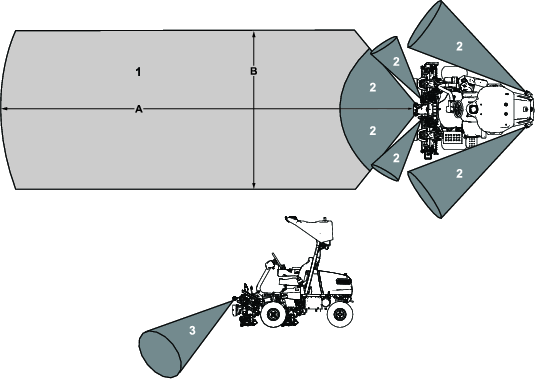
| Figure 33 reference | Measurement |
| A | 8 m (26 ft) |
| B | 3 m (10 ft) |
If the machine senses a static object within the courtesy zone of the machine, the machine will start slowing down and the amber lights will start flashing with higher frequency. Once the machine has approached the object and the object is just outside of a hazard zone, the machine will start idling, the PTO disengages, and the machine will send a text to the supervisor’s mobile device after 1 minute. After the supervisor removes the object, they can remotely resume the mission using their mobile device.
If the machine abruptly senses an object within a hazard zone, the machine stops immediately, the PTO disengages, the engine turns off, and the machine goes into PARK and sends a text to the supervisor. The supervisor must then remove the object and manually cycle the autonomous/manual-mode switch to resume the mission.
Drop-off detection detects if the machine encounters a hazardous drop-off. If the machine encounters unsafe terrain, it will immediately go into PARK and send a text to the supervisor. The supervisor must then manually drive the machine to a safe area and cycle the autonomous/manual-mode switch to resume the mission.
Important: The drop-off detection system should never be activated if obstructions are properly mapped by the supervisor.Run a test mission to observe any issues with drop-offs. Create new AOAs, CMAs, or NOAs so that the machine avoids these areas with drop-offs.
Saving and Exporting Map Data
The supervisory app has a feature for exporting and sharing map files between machines in a fleet.
Important: It is recommended to designate one of your machines as the primary mapping machine for the course. This should be the only machine in your fleet that creates new mapped areas or modifies existing mapped areas.It is the supervisor’s responsibility to ensure that the correct map file is loaded onto every machine in a fleet.
-
Insert and rotate the key on the primary mapping machine to the ON position. Wait 2 minutes.
-
Connect to the machine using the GeoLink Mow supervisory app.
-
From the top menu bar, select the HELP button.
-
Select the Export map database button to create and download a copy of the map file.
This will save a copy of your map file to the downloads directory of your device.
-
Import the map file to other machines in your fleet:
-
Insert and rotate the key to the ON position for each non-primary machine.
-
Connect to each machine using the GeoLink Mow supervisory app.
-
From the top menu bar, select the SETTINGS button.
-
Turn off Lock map.
-
From the top menu bar, select the HELP button.
-
Select the Delete ALL map data button.
Note: Ensure that there are no active missions before selecting the button.
-
Select the Choose File button and open the file you downloaded earlier to your device.
-
Select the Import map database button.
-
In the SETTINGS menu, turn on Lock map.
-
Repeat these steps for all of the other machines in the fleet.
-
Bypassing the Autonomous Control System Using the Loopback Connector
If the autonomous control system is not available or not functioning properly, it may be required to bypass the system in order to manually operate the machine.
-
Remove the right-side cover for the electrical system; refer to Locating the Fuses for the 12V System.
-
Locate the connector on the main machine wire harness and install the loopback connector.
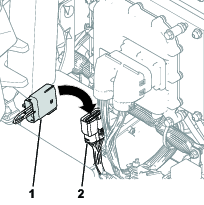
Mowing the Green Manually
Before mowing greens, find a clear area and practice performing basic machine functions (e.g., starting and stopping the machine, raising and lowering the cutting units, and turning).
Inspect the greens for debris, remove anything that may damage the cutting units while mowing, remove the flag from the cup, and determine the best direction to mow. Base the direction to mow on the previous mowing direction. Always mow in an alternate pattern from the previous mowing so that the grass blades are less apt to lay down and will have a greater chance of being cut.
Cutting the Green
-
Start on 1 edge of the green so that you can use the ribbon procedure of cutting.
Note: This holds compaction to a minimum and leaves a neat, attractive pattern on the greens.
-
Move the function-control switch to the MOW position.
-
Push forward the lift/lower mow lever as the front edges of the cutting units cross the outer edge of the green.
Note: This procedure drops the cutting units to the turf and starts the reels.
Important: The center cutting unit lifts or lowers slightly after the front cutting units do; therefore, you should practice gaining the required timing necessary to minimize the cleanup mowing operation and prevent scalping of the fringe.The center cutting unit lift and lower is based on ground speed. A slower ground speed increases the lift or lower delay; a faster speed decreases the lift or lower delay. The machine monitors the ground speed and updates this delay so that all three cutting units drop in a line.
-
Overlap a minimal amount with the previous cut on return passes.
Note: To assist in maintaining a straight line across the green and keeping the machine an equal distance from the edge of the previous cut, imagine a sight line approximately 1.8 to 3 m (6 to 10 ft) ahead of the machine to the edge of the uncut portion of the green (Figure 36). Include the outer edge of the steering wheel as part of the sight line; i.e., keep the steering wheel edge aligned with a point that is always kept the same distance away from the front of the machine.
-
As the front edges of the baskets cross the edge of the green, pull back the lift/lower joystick rearward and hold it until all the cutting units have risen. This stops the reels and lifts the cutting units.
Important: Time this step correctly so that you do not cut into the fringe area, yet cut as much of the green as possible to minimize the amount of grass left to mow around the outer periphery.
-
To cut down on operating time and to ease the lineup for the next pass, momentarily turn the machine in the opposite direction, then turn it in the direction of the uncut portion. This movement is a tear-shaped turn (Figure 35), which quickly lines the machine up for your next pass.
Note: If the slow in turn function is engaged, the machine slows down during the turn without requiring you to release pressure on the traction pedal.
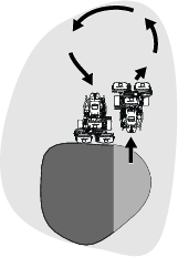
Note: Try to make as short of a turn as possible, except during warmer weather—a wider arc minimizes the turf bruising.
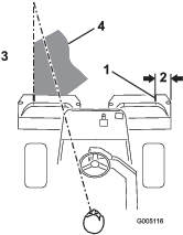
Important: Never stop the machine on a green, especially while the cutting units are engaged; damage to the turf may result. Stopping the machine on a green may leave marks or indentations from the wheels.
Cutting the Periphery and Finishing the Job
-
Finish cutting the green by mowing the outer periphery. Change the direction of cutting from the previous mowing.
Refer to Cutting the Periphery and Finishing the Job to improve the after-cut appearance and reduce triplex ring.
Note: Always keep weather and turf conditions in mind and be sure to change the direction of mowing from the previous cutting.
-
When you finish mowing the outer periphery, tap the lift/lower joystick rearward to stop the reels (if the tap-off delay feature is engaged), then drive off the green. When all the cutting units are off the green, move the lift/lower joystick rearward to raise the cutting units.
Note: This step minimizes grass clumps left on the green.
-
Replace the flag.
After Operation
Inspecting and Cleaning after Mowing
| Maintenance Service Interval | Maintenance Procedure |
|---|---|
| Before each use or daily |
|
After mowing, thoroughly wash the machine with a garden hose without a nozzle so that excessive water pressure does not contaminate and damage the seals, bearings, and electronics. Do not wash a warm engine or the electrical connections with water.
Important: Do not use brackish or reclaimed water to clean the machine.
Important: Do not use power-washing equipment to wash the machine. Power-washing equipment may damage the electrical system, loosen important decals, or wash away necessary grease at friction points. It may force water under seals, contaminating oil or grease contained housings. Avoid excessive use of water near the control panel, engine, and battery.
Important: Do not wash the machine with the engine running. Washing the machine with the engine running may result in internal engine damage.
Important: Do not force water into the muffler. Water inside the muffler may result in internal engine damage or reduced engine performance.
Inspect the cutting units for sharpness after you clean the machine.
Hauling the Machine
-
Use care when loading or unloading the machine into a trailer or a truck.
-
Use a full-width ramp for loading the machine into a trailer or a truck.
-
Tie the machine down securely using straps, chains, cable, or ropes. Both front and rear straps should be directed down and outward from the machine (Figure 37).
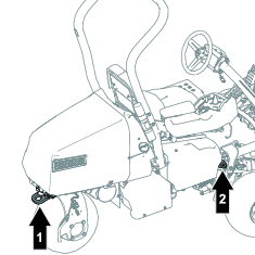
-
After the machine is secured for transport, close the fuel-shutoff valve.
Towing the Machine
Note: Refer to Figure 38 for this procedure.
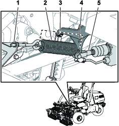
To tow the machine, you must perform the following procedure to release the brake actuator:
-
Engage the parking brake.
-
Remove the key and disconnect the main-power connectors.
Important: If the main-power connectors are connected while towing, electrical damage may result.
-
Close the fuel-shutoff valve.
-
Chock both sides of the front tires.
-
Release tension on the spring by loosening the nut that secures the eyebolt to the spring bracket.
-
Remove the spring.
-
Insert a ratchet (3/8 inch) through the hole of the arm bracket and push in the actuator shaft.
Danger
When the actuator is released from the brake, the machine is able to free wheel. A free-wheeling machine can cause serious injury to bystanders.
If the machine is not being towed, engage the parking brake.
-
Engage the parking brake.
-
Remove the chocks from the tires.
-
If the 3-Wheel Drive Kit is installed, disconnect the kit-wire-harness connectors from the main wire harness.
Important: If the kit and machine wire harnesses are connected while towing, electrical damage may result.
-
When the machine is ready to be towed, disengage the parking brake.
-
Have an assistant sit in the seat, fasten the seatbelt, and use the brake while you tow the machine.
Note: This ensures that the machine is under control when you tow the machine over undulations and slopes.
-
Use the rear castor fork to tow the machine (Figure 39).
Important: Do not exceed 5 km/h (3 mph) while towing the machine. Damage to the electrical components may result.
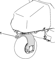
After you have towed the machine to your intended destination, perform the following steps:
-
Engage the parking brake.
-
Remove the tow strap from the castor fork.
-
Prepare for operation by tightening the eyebolt nut so that the spring length is 11.4 cm (4.5 inches) when installed (Figure 38).
Driving the Machine Without Engine Power
You can drive the machine using the battery power of the machine. This feature can be used for the following scenarios:
-
Moving the machine in the maintenance shop.
-
Moving the machine off of the green if the engine shuts off.
The machine can be transported only; you cannot engage the cutting units. This feature lasts for 1 minute, and you can cycle the key switch to reset the minute of transport time.
-
Sit in the operator’s seat and fasten the seatbelt.
-
Move the key to the ON position.
-
Move the function-control switch to the MOW or TRANSPORT position.
-
Disengage the parking brake.
-
Use the traction pedal to transport the machine.
Note: Forward ground speed is limited to 4.8 km/h (3.0 mph), and reverse ground speed is limited to 4.0 km/h (2.5 mph).
Important: Excessive or prolonged use of this feature may decrease the life of the batteries.
Maintenance
Recommended Maintenance Schedule(s)
| Maintenance Service Interval | Maintenance Procedure |
|---|---|
| After the first 8 hours |
|
| After the first 50 hours |
|
| Before each use or daily |
|
| Every 25 hours |
|
| Every 50 hours |
|
| Every 100 hours |
|
| Every 200 hours |
|
| Every 800 hours |
|
| Every 1,000 hours |
|
| Every 2 years |
|
Pre-Maintenance Procedures
Raising the Machine
Danger
Mechanical or hydraulic jacks may fail to support the machine and cause a serious injury.
-
Use jack stands to support the raised machine.
-
Use only mechanical or hydraulic jacks to lift the machine.
-
Position a jack at the desired jacking point (Figure 40):
-
Foot step on the left side of the machine
-
Jack bracket on the right side of the machine
-
Caster fork on the rear of the machine
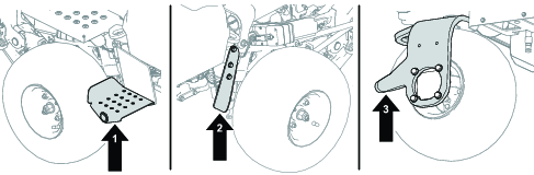
-
-
After raising the machine, use an appropriate jack stand under the following areas to support the machine (Figure 41):
-
Battery trays at the rear of the machine
-
Cutting-unit pivot mounts at the front of the machine
-
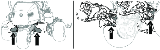
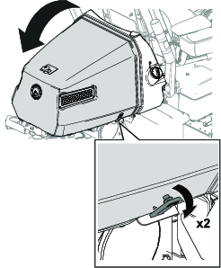
Engine Maintenance
Servicing the Air Cleaner
| Maintenance Service Interval | Maintenance Procedure |
|---|---|
| Every 25 hours |
|
| Every 100 hours |
|
| Every 200 hours |
|
Inspect the foam and paper elements and replace them if they are damaged or excessively dirty.
Important: Do not oil the foam or paper element.
Removing the Foam and Paper Elements
-
Park the machine on a level surface, lower the cutting units, and engage the parking brake.
-
Shut off the engine and remove the key.
-
Clean around the air cleaner to prevent dirt from getting into the engine and causing damage (Figure 43).
-
Loosen the cover knobs and remove the air-cleaner cover (Figure 43).
-
Loosen the hose clamp and remove the air-cleaner assembly (Figure 43).
-
Carefully pull the foam element off the paper element (Figure 43).
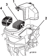
Cleaning the Foam Air-Cleaner Element
-
Wash the foam element in liquid soap and warm water. When the element is clean, rinse it thoroughly.
-
Dry the element by squeezing it in a clean cloth.
Important: Do not twist the foam element, as it may tear.Replace the foam element if it is torn or worn.
Servicing the Paper Air-Cleaner Element
-
Clean the paper element by tapping it gently to remove dust. If it is very dirty, replace the paper element (Figure 43).
-
Inspect the element for tears, an oily film, or damage to the rubber seal.
-
Replace the paper element if it is damaged.
Important: Do not clean the paper filter.
Installing the Foam and Paper Air-Cleaner Elements
Important: To prevent engine damage, always operate the engine with the complete foam and paper air-cleaner assembly installed.
Servicing the Engine Oil
The engine is shipped with oil in the crankcase; however, you must check the oil level before and after starting the engine the first time.
Engine-Oil Specification
API Oil Service Classification: SJ or higher
Oil Viscosity: SAE 30
Note: Use any high-quality detergent oil.
Checking the Engine Oil
| Maintenance Service Interval | Maintenance Procedure |
|---|---|
| Before each use or daily |
|
Caution
Engines can become extremely hot during normal operation.
Allow the engine to cool before you check the oil or perform any engine maintenance.
Refer to Figure 44 for this procedure.
-
Park the machine on a level surface, lower the cutting units, engage the parking brake, shut off the engine, and remove the key.
-
Unscrew the dipstick, remove it, and wipe it with a clean rag.
-
Insert the dipstick into the dipstick tube.
-
Pull the dipstick out of the tube and check the oil level.
-
If the oil level is low, add oil into the engine through the dipstick tube until the oil level is up to the FULL mark on the dipstick.
Add the oil slowly and check the level often during this process.
Important: Do not overfill the engine with oil.
-
Install the dipstick.

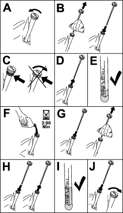
Changing the Engine Oil and Filter
| Maintenance Service Interval | Maintenance Procedure |
|---|---|
| After the first 8 hours |
|
| Every 100 hours |
|
Caution
Engines can become extremely hot during normal operation.
Allow the engine to cool before you change the oil or oil filter, or perform any engine maintenance.
Engine oil quantity: 1.7 L (1.8 US qt) with filter
-
Remove the drain plug (Figure 45) and let the oil flow into a drain pan.
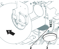
-
Clean the threads of the drain plug and install the drain plug (Figure 45).
-
Remove the oil filter (Figure 46).

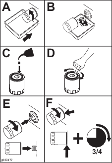
-
Apply a light coat of clean oil to the new filter gasket.
-
Screw the filter on by hand until the gasket contacts the filter adapter, then tighten it 3/4 to 1 turn further. Do not overtighten it.
-
Add oil to the crankcase; refer to Checking the Engine Oil.
-
Dispose of the oil filter and used oil properly.
Servicing the Spark Plug
| Maintenance Service Interval | Maintenance Procedure |
|---|---|
| Every 100 hours |
|
Caution
Engines can become extremely hot during normal operation.
Allow the engine to cool before you service the spark plug or perform any engine maintenance.
Ensure that the air gap between the center and side electrodes is correct before installing the spark plug. Use a spark plug wrench for removing and installing the spark plug(s) and a gapping tool/feeler gauge to check and adjust the air gap. Install a new spark plug(s) if necessary.
Type of Spark Plug: NGK® BPR4ES or equivalent
Air Gap: 0.75 mm (0.03 inch)
Removing the Spark Plug
-
Park the machine on a level surface, lower the cutting units, and engage the parking brake.
-
Shut off the engine and remove the key.
-
Locate the spark-plug caps.
-
Clean the area around the spark plug caps so that foreign matter cannot fall into the cylinder.
-
Disconnect the spark plug caps from the spark plugs (Figure 47).
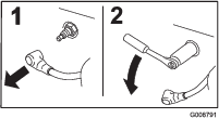
-
Remove the spark plugs from the engine.
Checking and Cleaning the Spark Plug
Important: Always replace the spark plug(s) when it has a black coating, worn electrodes, an oily film, or cracks.
-
Clean the spark plug with a wire brush to remove any carbon deposits.
Use carburetor cleaner to wash the plug and ensure any foreign matter has been removed.
-
Inspect the spark plugs for cracks, worn electrodes, black coating, or oily films or other wear or damage.
-
Replace the spark plug if necessary. Replace all spark plugs if only one requires replacing.
-
Check the spark plug gap and reset if necessary. To change the gap, bend only the side-electrode, using a spark plug tool.
Set the gap to 0.75 mm (0.03 inch).
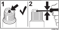
If you see light brown or gray on the insulator, the engine is operating properly. A black coating on the insulator usually means the air cleaner is dirty.
Installing the Spark Plug
Refer to Figure 49 for this procedure.
-
Install the spark plug into the engine.
-
Torque the spark plug to 22 N∙m (16 ft-lb).
-
Reconnect the spark plug caps.
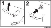
Fuel System Maintenance
Replacing the Fuel Filter
| Maintenance Service Interval | Maintenance Procedure |
|---|---|
| Every 1,000 hours |
|
The in-line fuel filter is between the fuel-shutoff valve and the engine.
Danger
In certain conditions, fuel is extremely flammable and highly explosive. A fire or explosion from fuel can burn you and others and can damage property.
-
Drain fuel from the fuel tank when the engine is cold. Do this outdoors in an open area. Wipe up any fuel that spills.
-
Never smoke when draining fuel, and stay away from an open flame or where a spark may ignite the fumes.
-
Close the fuel-shutoff valve (Figure 50).
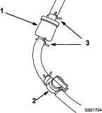
-
Place a drain pan under the filter, loosen the hose clamp on the carburetor side of filter, and remove the fuel line from the filter (Figure 50).
-
Loosen the other hose clamp and remove the filter.
-
Inspect the fuel lines for any cracks, deterioration, or damage and replace if necessary.
-
Install the new filter with the arrow on the filter body pointing away from the fuel tank.
-
Ensure the hoses and hose clamps are secure to the filter.
-
Open the fuel-shutoff valve and fill the tank. Inspect the fuel lines for any leaks or loose connections.
Inspecting the Fuel Lines and Connections
| Maintenance Service Interval | Maintenance Procedure |
|---|---|
| Every 2 years |
|
Inspect the fuel lines for deterioration, damage, or loose connections.
Electrical System Maintenance
Disconnecting or Connecting Power to the Machine
The main-power connectors provide power from the batteries to the machine. Disconnect the power by separating the connectors; connect the power by installing the connectors together. Refer to Main-Power Connectors.
Charging the 12V Battery to the 12V System
Warning
Incorrect battery cable routing could damage the machine and cables causing sparks. Sparks can cause the battery gasses to explode, resulting in personal injury.
-
Always disconnect the negative (black) battery cable before disconnecting the positive (red) cable.
-
Always connect the positive (red) battery cable before connecting the negative (black) cable.
The 12V AGM (absorbed glass mat) battery (Figure 51) powers the InfoCenter, brake actuator, machine controller, and the CAN isolation module.
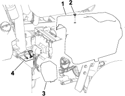
-
Remove the right side cover.
-
Remove the battery cover.
-
Disconnect the battery cables from the batteries.
-
Connect the charger to the battery terminals and charge the battery.
Note the following information for your battery charger:
-
Ensure that the battery-charger connectors do not contact each other or the machine frame. Using smaller connectors is recommended.
-
A battery charger with an AGM-charging setting is preferred.
-
Maximum charge current: 2.4 A
-
Maximum charge voltage: 14.3 V
-
-
Connect the battery cables to the battery when the charge is completed.
-
Install the battery cover over the battery.
-
Install the right side cover.
Understanding the 48V Battery System
Important: Charging the 48V battery system is not recommended.
The 48V battery system consists of 4 batteries (12V, AGM [absorbed glass mat]). The batteries are located under covers on each side of the machine; refer to Figure 52. This system provides power to the traction wheels, cutting-unit motors, steering motor, and lift actuators.
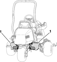
Locating the Fuses
Locating the Fuses for the 48V System
The fuses in the 48V electrical system are located under the seat (Figure 53).
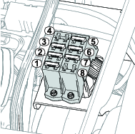
Locating the Fuses for the 12V System
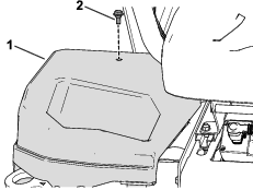
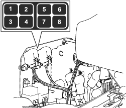
Locating the Reel-Drive Circuit Fuses
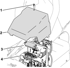
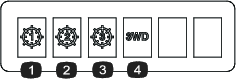
Locating the Generator, Wheel Motor, and Electrical System Fuses
-
The fuses for the generator (100 A) and the right wheel motor (60 A) are located under the seat (Figure 58).
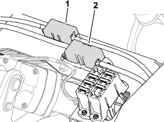
-
The fuse for the left wheel motor (60 A) is located under the cover on the left side of the machine, near the reel-drive-circuit fuses (Figure 59).
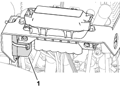
-
The fuse for the electrical system is located under the main-power connectors (Figure 60).
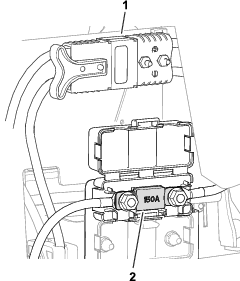
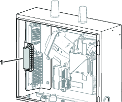
Drive System Maintenance
Checking the Tire Pressure
| Maintenance Service Interval | Maintenance Procedure |
|---|---|
| Before each use or daily |
|
Vary the tire pressure for all 3 wheels, depending upon your turf conditions, from a minimum of 83 to a maximum of 110 kPa (12 psi to 16 psi).
Important: Ensure that the tire pressure for each wheel is identical. If the tire pressure for each wheel is different, the performance of the machine is affected.
Checking the Torque of the Wheel Nuts
| Maintenance Service Interval | Maintenance Procedure |
|---|---|
| After the first 8 hours |
|
| Every 200 hours |
|
Warning
Failure to maintain proper torque of the wheel nuts could result in personal injury.
Torque the wheel nuts to the specified torque at the specified intervals.
Wheel-nut torque specification: 108 to 122 N∙m (80 to 90 ft-lb)
To ensure even distribution, torque the wheel nuts in the pattern shown in Figure 63.

Changing the Traction-Motor-Gearbox Fluid
| Maintenance Service Interval | Maintenance Procedure |
|---|---|
| After the first 8 hours |
|
| Every 800 hours |
|
Fluid specification: SAE 80W90
Gearbox oil capacity: approximately 384 ml (13 fl oz)
-
Raise the machine; refer to Raising the Machine.
Important: The machine must be level so that the correct amount of fluid can be added to the gearbox.Ensure that the machine is level on the jack stands.
-
Perform the following steps to remove the left and right-sided tires:
-
Loosen and remove the wheel lug nuts (Figure 64).
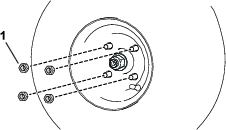
-
Remove the left and right tires.
-
-
Place a drain pan under the wheel-motor assembly (Figure 65).
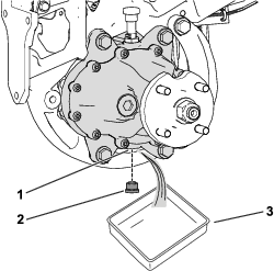
-
Remove the plug from the drain port (Figure 65).
Note: The drain port is located on the bottom of the gearbox.
Note: Allow the oil to drain completely from the gearbox.
-
Clean the plug.
-
Install the drain plug into the drain port (Figure 65).
-
Remove the vent hose and fitting from the top of the gearbox (Figure 66).
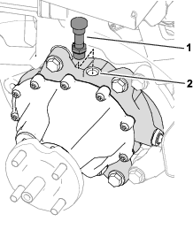
-
Fill the gearbox with 384 ml (13 fl oz) of the specified fluid through the fill port.
-
Install the vent hose and fitting into the fill port (Figure 66).
-
Perform the following steps to install the tires:
-
Slide the left and right tires on to the wheel hubs.
-
Install the wheel lug nuts (Figure 64).
-
Torque the wheel lug nuts to the specified torque indicated in Checking the Torque of the Wheel Nuts.
-
Brake Maintenance
Adjusting the Brakes
If the brake fails to hold the machine while parked, you can adjust the brakes; contact your authorized Toro distributor or refer to the Service Manual for more information.
Cutting Unit Maintenance
Blade Safety
A worn or damaged blade or bedknife can break, and a piece could be thrown toward you or bystanders, resulting in serious personal injury or death.
-
Inspect the blades and bedknives periodically for excessive wear or damage.
-
Use care when checking the blades. Wear gloves and use caution when servicing them. Only replace or backlap the blades and bedknives; never straighten or weld them.
-
On machines with multiple cutting units, take care when rotating a cutting unit; it can cause the reels in the other cutting units to rotate.
Installing and Removing the Cutting Units
Note: When the cutting units are not connected to the machine, store the cutting unit reel motors in the storage location on the front of the suspension arms to prevent damage to them.
Important: Do not raise the suspension to the transport position when the reel motors are in the holders in the machine frame. Damage to the motors or hoses could result.
Important: Whenever you need to tip the cutting unit, prop up rear of cutting unit to ensure that the nuts on the bedbar adjusting screws are not resting on work surface (Figure 67).

Installing the Cutting Units
Caution
Contact with a hot engine or muffler can cause severe burns.
Wait for a hot engine or muffler to cool before installing the cutting units.
The suspension needs to be lowered in order to install the cutting units. Perform the following steps to lower the suspension:
-
Park the machine on a clean, level surface.
-
Set the function-control switch to the NEUTRAL position.
-
Start the engine or turn the key to the ON position.
-
Lower the suspension using the lift/lower joystick.
-
Engage the parking brake, shut off the engine, and remove the key.
Perform the following steps to install the cutting units:
-
Disconnect the main-power connectors; refer to Main-Power Connectors.
Caution
If you do not disconnect the power to the machine, someone could accidentally start the cutting units, causing serious injury to hands and feet.
Always disconnect the main-power connectors before working on the cutting units.
-
Position the cutting unit under the center suspension arm.
-
Open the latches on the suspension-arm bar (Figure 68) and push the suspension arm down so that the bar fits over both pitch arms on the cutting unit and ensure that the latches go underneath the cutting-unit crossbar (Figure 69).
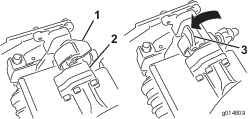
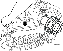
-
Close the latches down and around the cutting-unit bar and lock them in place (Figure 68).
Note: You can hear a click and feel when the latches are properly locked in place.
-
Coat the spline shaft of the cutting unit motor with clean grease (Figure 70).
-
Insert the motor into the left side of the cutting unit (as viewed from the operator's position) and pull the motor retaining bar on the cutting unit toward the motor until you hear a click from both sides of the motor (Figure 70).
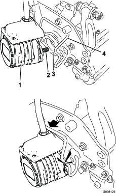
-
Repeat this procedure for the other cutting units.
-
Connect the main-power connectors; refer to Main-Power Connectors.
Removing the Cutting Units
Caution
Contact with a hot engine or muffler can cause severe burns.
Wait for a hot engine or muffler to cool before installing the cutting units.
-
Park the machine on a clean, level surface, set the function-control switch to the NEUTRAL position and use the lift/lower joystick to lower the cutting units.
-
Engage the parking brake, shut off the engine, and remove the key.
-
Disconnect the main-power connectors; refer to Main-Power Connectors.
Caution
If you do not disconnect the power to the machine, someone could accidentally start the cutting units, causing serious injury to hands and feet.
Always separate the disconnect the main-power connectors before working on the cutting units.
-
Push the motor retaining bar out of the slots on the motor toward the cutting unit and remove the motor from the cutting unit.
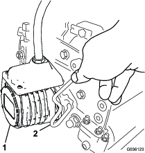
-
Move the motor to the storage location on the front of the suspension arm (Figure 72).
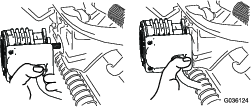
Note: When sharpening, setting the height-of-cut, or performing other maintenance procedures on the cutting units, store the cutting unit reel motors in the storage location on the front of the suspension arms to prevent damage to them.
Important: Do not raise the suspension to the transport position when the reel motors are in the holders in the machine frame. Damage to the motors or hoses could result. If you must move the traction unit without the cutting units installed, secure them to the suspension arms using cable ties.
-
Open the latches on the suspension-arm bar of the cutting unit you are removing (Figure 68).
-
Disconnect the latches from the cutting-unit bar.
-
Roll the cutting unit out from under the suspension arm.
-
Repeat steps 4 through 8 for the other cutting units as required.
-
Connect the main-power connectors; refer to Main-Power Connectors.
Checking the Reel-to-Bedknife Contact
| Maintenance Service Interval | Maintenance Procedure |
|---|---|
| Before each use or daily |
|
Each day before operating the machine, check the reel-to-bedknife contact, regardless if the quality of cut had previously been acceptable. There must be light contact across the full length of the reel and bedknife; refer to the cutting unit Operator’s Manual.
Before checking the reels, disconnect the main-power connectors; refer to Main-Power Connectors. Connect them when finished.
Backlapping the Cutting Units
Warning
Contact with the bedknives, reel blades, or other moving parts can result in personal injury.
-
Keep your fingers, hands, and clothing away from the bedknives, reel blades, or moving parts.
-
Never attempt to turn the reels by hand or foot while the engine is running.
-
Park the machine on a level surface, lower the cutting units, move the function-control switch to the NEUTRAL position, engage the parking brake, shut off the engine, and remove the key.
-
Make initial reel-to-bedknife adjustments appropriate for backlapping on all cutting units that you want to backlap; refer to the cutting unit Operator’s Manual.
-
Insert the key into the switch and start the engine.
-
On the InfoCenter control, from the SERVICE menu, select BACKLAP.
-
Set BACKLAP to ON.
-
Pull up the Main Menu and scroll down to Settings.
-
In the SETTINGS menu scroll down to BACKLAP RPM and use the ± button to select the desired backlap speed.
-
With the function-control switch in the NEUTRAL position, move the lift/lower joystick forward to start the backlapping operation on the designated reels.
-
Apply lapping compound with a long handle brush. Never use a short handled brush.
-
If the reels stall or become erratic while backlapping, select a higher reel speed setting until the speed stabilizes.
-
To make an adjustment to the cutting units while backlapping, turn the reels off by moving the lift/lower joystick rearward and shut off the engine. After completing adjustments, repeat steps 3 through 9.
-
Repeat the procedure for all cutting units that you want to backlap.
-
When finished, return the InfoCenter BACKLAP setting to OFF or turn the key to the OFF position to return the machine to forward cutting operation.
-
Wash all lapping compound off of the cutting units. Adjust the cutting unit reel to bedknife as needed. Move the cutting-unit reel speed control to the desired mowing position.
Important: Do not use high pressure water to clean off the cutting units. Damage to the bearings and seals may result.
Sensor Maintenance
Inspecting the Sensors and Sensor Brackets
| Maintenance Service Interval | Maintenance Procedure |
|---|---|
| Before each use or daily |
|
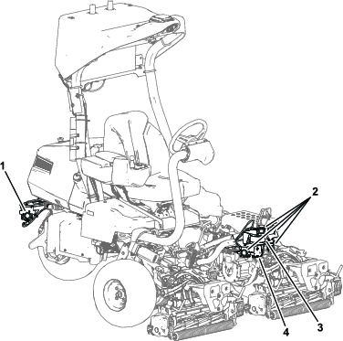
Danger
A bent or broken sensor or sensor bracket increases the possibility of a malfunctioning object detection system, which could cause serious injury or death.
If any sensors or sensor brackets are bent or broken, repair or replace them immediately.
Inspect the sensors and sensor brackets before operating the machine autonomously.
Cleaning
Cleaning the Sensors
| Maintenance Service Interval | Maintenance Procedure |
|---|---|
| Before each use or daily |
|
Clean the sensors whenever there is noticeable debris accumulation or they are not functioning.
Avoid over-cleaning the sensors as this could damage the sensor.
Refer to Figure 73 for the locations of the sensors.
Important: Do not use high-pressure water when cleaning any of the sensors.
Cleaning the Sonar and Radar Sensors
Using Simple Green® cleaner or other similar gentle soap, clean the sonar or radar sensors of any residue or debris.
Cleaning the LiDAR Sensor
Note: Avoid using hard water when cleaning the LiDAR sensor.
-
Determine the appropriate method of cleaning:
-
Look for the first 5 characters of the serial number on the sensor. The serial number is on a label on the underside of the sensor.
-
If the first 5 characters are between AE001–AE229, proceed to step 2.
-
If the first 5 characters are AE230 or greater, proceed to step 3 or 4.
-
-
Clean using soapy water.
-
Using a spray bottle with clean, warm water, loosen debris from the lens of the sensor.
Important: Do not directly wipe dirt or debris off the sensor. This could scratch the lens.
-
Gently wipe the sensor using a microfiber cloth with warm, mildly soapy water.
Note: Wipe along the curve of the lens rather than up and down the sensor.
-
Spray the sensor with clean water to rinse off any remaining soap, then dry using a clean microfiber cloth.
-
-
Clean using isopropyl alcohol.
-
Using a spray bottle with clean, warm water, loosen debris from the lens of the sensor.
Important: Do not directly wipe dirt or debris off the sensor. This could scratch the lens.
-
Using isopropyl alcohol and a clean microfiber cloth, clean any remaining dirt or debris from the sensor.
-
Gently wipe the sensor using a microfiber cloth with warm, mildly soapy water.
Note: Wipe along the curve of the lens rather than up and down the sensor.
-
Spray the sensor with clean water to rinse off any remaining soap, then dry using a clean microfiber cloth.
-
-
Clean using NACL Optics Cleaner.
North American Coating Laboratories (NACL) has formulated a cleaning solution for certain optical devices. It can be ordered from them directly using the following information:
-
NACL part number: 98-0020
-
NACL description: NACL Precision Optics Cleaner 6 oz
-
Spray NACL Precision Optics Cleaner solution onto a clean, dry microfiber cloth.
-
Gently wipe the sensor along the curve of the lens rather than up and down.
-
Storage
If you wish to store the machine for a long period of time, perform the steps listed in Preparing the Machine for Storage.
Preparing the Machine for Storage
If possible, store the machine in a warm, dry location.
The batteries—whether they are installed or removed from the machine—must be stored in the appropriate environment:
-
Recommended storage temperatures should be between 10°C to 25°C (50°F and 77°F).
-
Storage at extreme temperatures will result in accelerated rates of self discharge.
-
If temperatures are expected to drop well below freezing for an extended period, remove the batteries from the machine and store the batteries in a warmer environment.
-
Disconnect the main-power connectors; refer to Main-Power Connectors.
-
Remove accumulations of dirt and old grass clippings. Sharpen the reels and bedknives, if necessary; refer to the cutting unit Operator's Manual. Coat the bedknives and reel blades with a rust preventive.
-
All fuel should be removed from the fuel tank. Run the engine until it shuts off. Replace the fuel filter; refer to Replacing the Fuel Filter.
-
While the engine is still warm, drain the oil from the crankcase. Refill it with fresh oil; refer to Changing the Engine Oil and Filter.
-
Remove the spark plugs, pour 30 ml (1 fl oz) of SAE 30 oil into the cylinders, and crank to distribute the oil. Replace the spark plugs; refer to Servicing the Spark Plug.
-
Clean dirt and chaff from the cylinder, cylinder head fins, and blower housing.
-
Disconnect the battery cables from the 12V battery.
-
Ensure that the 12V and 48V batteries are fully charged; refer to the traction unit Service Manual for charging instructions.
For every 6 months of storage, check the battery-charge level and charge the battery.
-
Raise and support the machine to remove its weight from the tires.