| Maintenance Service Interval | Maintenance Procedure |
|---|---|
| Before each use or daily |
|
Introduction
This machine is a compact tool carrier intended for use in various earth and materials moving activities for landscaping and construction work. It is designed to operate a wide variety of attachments each of which perform a specialized function. Using this product for purposes other than its intended use could prove dangerous to you and bystanders. Do not modify the machine or attachments.
This machine should be operated, serviced, and repaired only by professionals familiar with its characteristics and acquainted with the relevant safety procedures.
Operate this machine in ambient temperatures from -18 to 38°C (0 to 100 °F). Contact your Authorized Service Dealer for provisions required for operating in extreme temperatures.
Read this information carefully to learn how to operate and maintain your product properly and to avoid injury and product damage. You are responsible for operating the product properly and safely.
Visit www.Toro.com for product safety and operation training materials, accessory information, help finding a dealer, or to register your product.
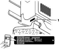
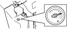
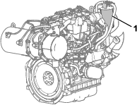
Whenever you need service, genuine Toro parts, or additional information, contact an Authorized Service Dealer or Toro Customer Service and have the model and serial numbers of your product ready. Figure 1 identifies the location of the model and serial numbers on the product. Write the numbers in the space provided.
Important: With your mobile device, you can scan the QR code on the serial number decal (if equipped) to access warranty, parts, and other product information.
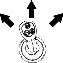
This manual identifies potential hazards and has safety messages identified by the safety-alert symbol (Figure 2), which signals a hazard that may cause serious injury or death if you do not follow the recommended precautions.

This manual uses 2 words to highlight information. Important calls attention to special mechanical information and Note emphasizes general information worthy of special attention.
This product complies with all relevant European directives; for details, please see the separate product specific Declaration of Conformity (DOC) sheet.
It is a violation of California Public Resource Code Section 4442 or 4443 to use or operate the engine on any forest-covered, brush-covered, or grass-covered land unless the engine is equipped with a spark arrester, as defined in Section 4442, maintained in effective working order or the engine is constructed, equipped, and maintained for the prevention of fire.
The enclosed engine owner's manual is supplied for information regarding the US Environmental Protection Agency (EPA) and the California Emission Control Regulation of emission systems, maintenance, and warranty. Replacements may be ordered through the engine manufacturer.
Warning
CALIFORNIA
Proposition 65 Warning
Diesel engine exhaust and some of its constituents are known to the State of California to cause cancer, birth defects, and other reproductive harm.
Battery posts, terminals, and related accessories contain lead and lead compounds, chemicals known to the State of California to cause cancer and reproductive harm. Wash hands after handling.
Use of this product may cause exposure to chemicals known to the State of California to cause cancer, birth defects, or other reproductive harm.
Safety
General Safety
Danger
There may be buried utility lines in the work area. Digging into them may cause a shock or an explosion.
Have the property or work area marked for buried lines and do not dig in marked areas. Contact your local marking service or utility company to have the property marked (for example, in the US, call 811 or in Australia, call 1100 for the nationwide marking service).
Always follow all safety instructions to avoid serious injury or death.
-
Do not exceed the rated operating capacity, as the machine may become unstable, which may result in loss of control.
-
Do not transport a load with the arms raised or extended; always transport loads close to the ground, with the loader arms retracted.
-
Slopes are a major factor related to loss-of-control and tip-over accidents, which can result in severe injury or death. Operating the machine on any slope or uneven terrain requires extra caution.
-
Operate the machine up and down slopes with the heavy end of the machine uphill and the load close to the ground and the loader arms retracted. Weight distribution changes with attachments. An empty load-bearing attachment makes the rear of the machine the heavy end, and a full load-bearing attachment makes the front of the machine the heavy end. Most other attachments make the front of the machine the heavy end.
-
Have the property or work area marked for buried lines and other objects, and do not dig in marked areas.
-
Read and understand the content of this Operator’s Manual before starting the engine.
-
Use your full attention while operating the machine. Do not engage in any activity that causes distractions; otherwise, injury or property damage may occur.
-
Never allow children or untrained people to operate the machine.
-
Keep your hands and feet away from the moving components and attachments.
-
Do not operate the machine without the guards and other safety protective devices in place and working on the machine.
-
Keep bystanders and pets away from the machine.
-
Stop the machine, shut off the engine, and remove the key before servicing, fueling, or unclogging the machine.
Improperly using or maintaining this machine can result in injury.
To reduce the potential for injury, comply with these safety instructions
and always pay attention to the safety-alert symbol  , which means Caution, Warning,
or Danger—personal safety instruction. Failure to comply with
these instructions may result in personal injury or death.
, which means Caution, Warning,
or Danger—personal safety instruction. Failure to comply with
these instructions may result in personal injury or death.
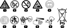
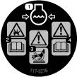
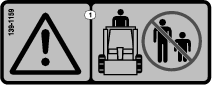
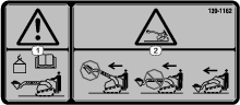
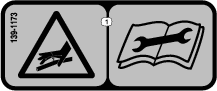
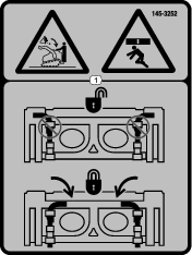
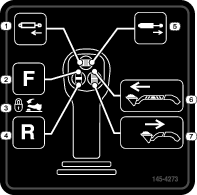
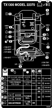
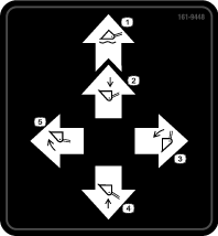
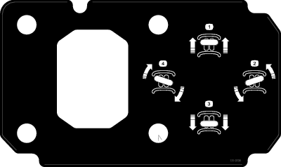
Safety and Instructional Decals
 |
Safety decals and instructions are easily visible to the operator and are located near any area of potential danger. Replace any decal that is damaged or missing. |


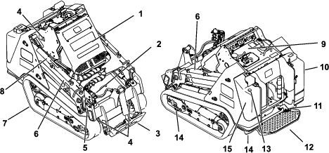
Product Overview
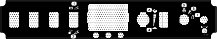
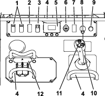
Control Panel
Become familiar with all the controls before you start the engine and operate the traction unit.
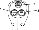
Key Switch
The key switch, used to start and shut off the engine, has 3 positions: OFF, RUN, and START.
Parking-Brake/Machine-Enable Switch
The traction and loader-arm controls are automatically disabled when starting the machine. The parking brake engages automatically when you shut off the machine.
Press the switch to disengage the parking brake and enable the traction and loader-arm controls; press the switch again to engage the parking brake and disable the controls.
Note: The light on the switch illuminates when the parking brake is engaged.
Throttle Switch
Hold the switch forward for 2 or more seconds to set the throttle at HIGH IDLE; hold the switch rearward for 2 or more seconds to set the throttle at LOW IDLE; or momentarily press the switch in either direction to increase or decrease the engine speed in smaller increments.
Reference Bar
When driving the traction unit, use the reference bar as a handle and a leverage point for controlling the traction control and the joystick lever. To ensure smooth, controlled operation, do not take your hands off the reference bars while operating the machine.
Traction Control
-
To move forward, move the traction control forward.

-
To move rearward, move the traction control rearward.
Important: When reversing, look behind you for obstructions and keep your hands on the reference bar.

-
To turn right, rotate the traction control clockwise.

-
To turn left, rotate the traction control counterclockwise.

-
To stop the machine, release the traction control.
Note: The farther you move the traction control in any direction, the faster the machine moves in that direction.
Loader Arm/Attachment-Tilt Lever
Slowly move the lever to operate the loader arms and tilt the attachment.
Note: The detent (float) position allows attachments such as the leveler and the hydraulic blade to follow the contours of the ground (i.e., float) when grading.
By moving the lever to an intermediate position (e.g., forward and left), you can move the loader arms and tilt the attachment at the same time.
Joystick Controls
Note: The loader arms may not extend when they are fully raised due to trapped pressure; lower the arms slightly to relieve pressure and extend them.
Warning
Moving the machine while the loader arms are extended may affect the stability of the machine.
Minimize machine movement while the loader arms are extended.
Auxiliary-Hydraulics Lock Switch
Engage the forward or reverse hydraulics, then use your right foot to press the lock switch to continue the flow and free your hand for other controls.
Fuel Gauge
This gauge measures the amount of fuel in the fuel tank(s).
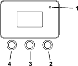
InfoCenter Display
The InfoCenter LCD display shows information about your machine, such as the operating status, various diagnostics and other information about the machine. There is a splash screen and main information screen of the InfoCenter. You can switch between the splash screen and main information screen at any time by pressing any of the InfoCenter buttons and then selecting the appropriate directional arrow.
-
Left Button, Menu Access/Back Button—press this button to access the InfoCenter menus. You can use it to exit any menu that you are currently using.
-
Middle Button—use this button to scroll down menus.
-
Right Button—use this button to open a menu where a right arrow indicates additional content.
Note: The purpose of each button may change depending on what is required at the time. Each button is labeled with an icon displaying its current function.
 | Menu access |
 | Next |
 | Previous |
 | Scroll down |
 | Enter |
 | Change the next value in the list |
 | Increase |
 | Decrease |
 | Save value |
 | Exit menu |
 | Accept |
 | The option is locked. |
 | Hour meter |
 | Adjust digit |
 | Warning |
 | Transport-speed screen access |
 | Fast |
 | Slow |
 | Neutral |
 | Auxiliary lock |
 | Cold start |
 | Parking brake |
 | Engine |
 | Glow plugs |
 | Engine-coolant temperature |
 | Engine speed |
 | Battery voltage |
 | Smart Load is active. |
 | Indicates when scheduled service should be performed |
 | DPF regeneration is required. |
 | A parked or recovery regeneration is processing. |
 | High exhaust temperature |
 | NOx control diagnosis malfunction; drive the machine back to the shop and contact your Authorized Service Dealer. |
Using the Menus
To access the InfoCenter menu system, press the menu access
button while
at the main screen. This will bring you to the main menu. Refer to
the following tables for a synopsis of the options available from
the menus:
| Menu Item | Description |
|---|---|
| Faults | The Faults menu contains a list of the recent machine and engine faults. Refer to the Service Manual or your Authorized Service Dealer for more information on the Faults menu and the information contained there. |
| Service | The Service menu contains information on the machine such as hours of use and other similar numbers. |
| Diagnostics | The Diagnostics menu displays the state of each machine switch, sensor and control output. You can use this to troubleshoot certain issues as it will quickly tell you which machine controls are on and which are off. |
| Settings | The Settings menu allows you to customize and modify configuration variables on the InfoCenter display. |
| About | The About menu lists the model number, serial number, and software version of your machine. |
| Menu Item | Description |
|---|---|
| Hours | Lists the total number of hours that the machine, engine, and auxiliary hydraulics have been on, as well as the number of hours for engine service and hydraulic service. |
| Counts | Lists the number of starts that the machine has experienced, the number of times the machine has warned that the engine temperature is too high, and the number of times the engine has shut off due to high temperatures. |
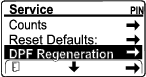
| DPF Regeneration | The DPF regeneration option and DPF submenus. |
| Inhibit Regen | Use to control reset regeneration. |
| Parked Regen | Use to initiate a parked regeneration. |
| Last Regen | Lists the number hours since the last reset, parked, or recovery regeneration. |
| Recover Regen | Use to initiate a recovery regeneration. |
| Menu Item | Description |
|---|---|
| Traction | Indicates the inputs and outputs for driving the machine. |
| Auxiliary | Indicates the inputs and outputs for engaging auxiliary hydraulics. |
| Engine | Indicates the inputs and outputs for starting the engine. |
| Boom | Indicates the inputs and outputs for extending and retracting the telescoping arms. |
| Menu Item | Description |
|---|---|
| Units | Controls the units used on the InfoCenter; the menu choices are Imperial or Metric. |
| Language | Controls the language used on the InfoCenter. |
| Brightness | Controls the brightness of the LCD display. |
| Contrast | Controls the contrast of the LCD display. |
| Protected Menus | Grants access to protected menus. |
| Protect Settings | Changes whether a pin is required in Protected Menus. |
| Menu Item | Description |
|---|---|
| Model | Lists the model number of the machine |
| Serial | Lists the serial number of the machine |
| Software | Lists the system software revision of the machine. |
| Display | Lists the display software revision of the InfoCenter. |
Accessing Protected Menus
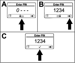
Note: The factory default PIN code for you machine is either 0000 or 1234.If you changed the PIN code and forgot the code, contact your Authorized Service Dealer for assistance.
-
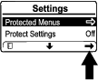
From the MAIN MENU, scroll down to the SETTINGS MENU and press the right button.

-
In the SETTINGS MENU, scroll down to the PROTECTED MENU and press the right button.
-
To enter the PIN code, press the center button until the correct first digit appears, then press the right button to move on to the next digit. Repeat this step until the last digit is entered and press the right button once more.
-
Press the middle button to confirm the PIN code.
Note: If the InfoCenter accepts the PIN code and the protected menu is unlocked, the word “PIN” displays in the upper right corner of the screen.
You can view and change the settings in the PROTECTED MENU. Once you access the PROTECTED MENU, scroll down to PROTECT SETTINGS option. Use the right button to change the setting. Setting the Protect Settings to OFF allows you to view and change the settings in the PROTECTED MENU without entering the PIN code. Setting the Protect Settings to ON hides the protected options and requires you to enter the PIN code to change the setting in the PROTECTED MENU.
Note: Specifications and design are subject to change without notice.
| Width | 116.8 cm (46.0 inches) |
| Length | 215.6 cm (84.9 inches) |
| Height | 143.5 cm (56.5 inches) |
| Weight | 1750 kg (3858 lb) |
| Operating capacity (35% of tipping capacity1) | |
| 589.7 kg (1300 lb) |
| 280 kg (618 lb) | |
| Tipping capacity1 | |
| 1685 kg (3714 lb) |
| 792 kg (1746 lb) | |
| Wheelbase | 99.1 cm (39.0 inches) |
| Dump height (with standard bucket) | |
| 180.1 cm (70.9 inches) |
| 230.3 cm (90.7 inches) | |
| Reach—fully raised (with standard bucket) | |
| 33.5 cm (13.2 inches) |
| 67.8 cm (26.7 inches) | |
| Height to hinge pin (with standard bucket in highest position) | |
| 227.1 cm (89.4 inches) |
| 277.3 cm (109.2 inches) |
1. The operating capacity is calculated as 35% of the tipping capacity with a standard bucket and 75 kg (165 lb) operator, per ISO 14397-1. Other attachments will have different operating capacities; refer to the Operator’s Manual or load capacity decal for the attachment.
Attachments/Accessories
A selection of Toro-manufactured attachments and accessories is available for use with the machine to enhance and expand its capabilities. Contact your Authorized Service Dealer or authorized Toro distributor or go to www.Toro.com for a list of all Toro-manufactured attachments and accessories.
To ensure optimum performance, use genuine Toro replacement parts and accessories. Toro accepts no liability for machine damage or personal injury that results from the use of other manufacturer attachments. The user accepts the burden of these risks.
Operation
Note: Determine the left and right sides of the machine from the normal operating position.
Before Operation
Before Operation Safety
General Safety
-
Never allow children or untrained people to operate or service the machine. Local regulations may restrict the age or require certified training of the operator. The owner is responsible for training all operators and mechanics.
-
Become familiar with the safe operation of the equipment, operator controls, and safety decals.
-
Always engage the parking brake (if equipped), shut off the engine, remove the key, wait for all moving parts to stop, and allow the machine to cool before adjusting, servicing, cleaning, or storing the machine.
-
Know how to stop the machine and shut off the engine quickly.
-
Check that the operator's presence controls, safety switches, and shields are attached and functioning properly. Do not operate the machine unless they are functioning properly.
-
Locate the pinch-point areas marked on the machine and attachments; keep your hands and feet away from these areas.
-
Before operating the machine with an attachment, ensure that the attachment is properly installed and that it is a genuine Toro attachment. Read all the attachment manuals.
-
Evaluate the terrain to determine what accessories and attachments you need to properly and safely perform the job.
-
Have the property or work area marked for buried lines and other objects, and do not dig in marked areas; note the location of unmarked objects and structures, such as underground storage tanks, wells, and septic systems.
-
Inspect the area where you will use the equipment for uneven surfaces or hidden hazards.
-
Ensure that the area is clear of bystanders before operating the machine. Stop the machine if anyone enters the area.
Fuel Safety
-
Use extreme care when handling fuel. It is flammable and its vapors are explosive.
-
Extinguish all cigarettes, cigars, pipes, and other sources of ignition.
-
Use only an approved fuel container.
-
Do not remove the fuel cap or fill the fuel tank while the engine is running or hot.
-
Do not add or drain fuel in an enclosed space.
-
Do not store the machine or fuel container where there is an open flame, spark, or pilot light, such as on a water heater or other appliance.
-
If you spill fuel, do not attempt to start the engine; avoid creating any source of ignition until the fuel vapors have dissipated.
-
To prevent a static charge from igniting the fuel, remove the machine from the truck or trailer and refuel it on the ground, away from all vehicles. If this is not possible, place a portable fuel container on the ground, away from all vehicles, and fill it; then refuel the machine from the fuel container rather than from a fuel-dispenser nozzle.
-
Keep the fuel-dispenser nozzle in contact with the rim of the fuel tank or container opening at all times until fueling is complete. Do not use a nozzle lock-open device.
Adding Fuel
Recommended Fuel
Use only clean, fresh diesel fuel or biodiesel fuels with ultra low (<15 ppm) sulfur content. The minimum cetane rating should be 45. A cetane rating greater than 50 is preferred, especially at temperatures below -20°C (-4°F) or at elevations above 1500 m (5000 ft). Purchase fuel in quantities that you can use within 180 days to ensure fuel freshness.
Using non-ultra low sulfur fuel will damage the engine emissions system.
Use summer-grade diesel fuel (No. 2-D or No. 2-D S15) at temperatures above -10°C (14°F) and winter grade (No. 1-D or No. 1-D S15) below that temperature. Using winter-grade fuel at lower temperatures provides lower flash point and cold flow characteristics, which eases starting and reduces fuel filter plugging.
Using summer-grade fuel above -10°C (14°F) contributes toward longer fuel pump life and increased power compared to winter-grade fuel.
Important: Do not use kerosene or gasoline instead of diesel fuel. Failure to observe this caution will damage the engine.
Biodiesel Ready
This machine can also use a biodiesel blended fuel of up to B5 (5% biodiesel, 95% petrodiesel). The petrodiesel portion should be low or ultra low sulfur. Observe the following precautions:
-
The biodiesel portion of the fuel must meet specification ASTM D6751 or EN14214.
-
The blended fuel composition should meet ASTM D975 or EN590.
-
Painted surfaces may be damaged by biodiesel blends.
-
Use B5 (biodiesel content of 5%) or lesser blends in cold weather.
-
Monitor seals, hoses, gaskets in contact with fuel as they may degrade over time.
-
Fuel filter plugging may occur for a time after converting to biodiesel blends.
-
Contact your distributor for more information on biodiesel.
Filling the Fuel Tank
Fuel tank capacity: 43.5 L (11.5 US gallons)
-
Park the machine on a level surface, engage the parking brake, and lower the loader arms.
-
Shut off the engine and remove the key.
-
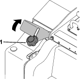
Raise the bracket.
-
Remove the fuel cap.
-
Fill the tank with fuel up to the filler neck.
-
Install the cap.
-
Lower the bracket.
Performing Daily Maintenance
Before starting the machine each day, perform the Each Use/Daily procedures listed in the .
Important: Check the hydraulic-fluid level and bleed the fuel system before starting the engine for the first time; refer to Checking the Hydraulic-Fluid Level and Bleeding the Fuel System.
During Operation
During Operation Safety
General Safety
-
Do not exceed the rated operating capacity, as the machine may become unstable, which may result in loss of control. The operating capacity is reduced if you extend the loader arms to the point where you can see the striped decal inside the arms.
-
Do not transport an attachment/load with the arms raised or extended; always transport the attachments/load close to the ground, with the loader arms retracted.
-
Attachments can change the stability and the operating characteristics of the machine.
-
For machines with a platform:
-
Lower the loader arms before stepping off the platform.
-
Do not try to stabilize the machine by putting your foot on the ground. If you lose control of the machine, step off the platform and away from the machine.
-
Do not place your feet under the platform.
-
Do not move the machine unless you are standing with both feet on the platform and your hands are holding onto the reference bars or the loader control.
-
-
Use your full attention while operating the machine. Do not engage in any activity that causes distractions; otherwise, injury or property damage may occur.
-
Look behind and down before backing up to ensure that the path is clear.
-
Never jerk the controls; use a steady motion.
-
The owner/user can prevent and is responsible for accidents that may cause personal injury or property damage.
-
Wear appropriate clothing including eye protection, long pants, substantial slip-resistant footwear, and hearing protection; also wear a respirator or dust mask in dusty conditions. Tie back long hair and do not wear loose clothing or loose jewelry.
-
Do not operate the machine when you are tired, ill, or under the influence of alcohol or drugs.
-
Never carry passengers and keep pets and bystanders away from the machine.
-
Operate the machine only in good light, keeping away from holes and hidden hazards.
-
Ensure that all the drives are in neutral before starting the engine. Start the engine only from the operator's position on the platform.
-
Use care when approaching blind corners, shrubs, trees, or other objects that may obscure vision.
-
Slow down and use caution when making turns and crossing roads and sidewalks. Watch for traffic.
-
Stop the attachment when you are not working.
-
Stop the machine, shut off the engine, remove the key, and inspect the machine if you strike an object. Make any necessary repairs before resuming operation.
-
Never run an engine in an enclosed area.
-
Never leave a running machine unattended.
-
Before leaving the operating position, do the following:
-
Park the machine on a level surface.
-
Lower the loader arms and disengage the auxiliary hydraulics.
-
Engage the parking brake.
-
Shut off the engine and remove the key.
-
-
Do not operate the machine when there is the risk of lightning.
-
Operate the machine only in areas where there is sufficient clearance for you to safely maneuver. Be aware of obstacles in close proximity to you. Failure to maintain adequate distance from trees, walls, and other barriers may result in injury as the machine backs up during operation if you are not attentive to the surroundings.
-
Check for overhead clearance (i.e., electrical wires, branches, and doorways) before driving under any objects and do not contact them.
-
Do not overfill the attachment and always keep the load level when raising the loader arms. Items in the attachment could fall and cause injury.
Slope Safety
-
Operate the machine up and down slopes with the heavy end of the machine uphill. Weight distribution changes with attachments. An empty load-bearing attachment makes the rear of the machine the heavy end, and a full load-bearing attachment makes the front of the machine the heavy end. Most other attachments make the front of machine the heavy end.
-
Raising or extending the loader arms on a slope affects the stability of the machine. Keep the loader arms in the lowered and retracted position when on slopes.
-
Slopes are a major factor related to loss of control and tip-over accidents, which can result in severe injury or death. Operating the machine on any slope or uneven terrain requires extra caution.
-
Establish your own procedures and rules for operating on slopes. These procedures must include surveying the site to determine which slopes are safe for machine operation. Always use common sense and good judgment when performing this survey.
-
Slow down and use extra care on hillsides. Ground conditions can affect the stability of the machine.
-
Avoid starting or stopping on a slope. If the machine loses traction, proceed slowly, straight down the slope.
-
Avoid turning on slopes. If you must turn, turn slowly and keep the heavy end of the machine uphill.
-
Keep all movements on slopes slow and gradual. Do not make sudden changes in speed or direction.
-
If you feel uneasy operating the machine on a slope, do not do it.
-
Watch for holes, ruts, or bumps, as uneven terrain could overturn the machine. Tall grass can hide obstacles.
-
Use caution when operating on wet surfaces. Reduced traction could cause sliding.
-
Evaluate the area to ensure that the ground is stable enough to support the machine.
-
Use caution when operating the machine near the following:
-
Drop-offs
-
Ditches
-
Embankments
-
Bodies of water
The machine could suddenly roll over if a track goes over the edge or the edge caves in. Maintain a safe distance between the machine and any hazard.
-
-
Do not remove or add attachments on a slope.
-
Do not park the machine on a hillside or slope.
Utility Line Safety
-
If you strike a utility line, do the following:
-
Shut off the machine and remove the key.
-
Remove all individuals from the work area.
-
Immediately contact the proper emergency and utility authorities to secure the area.
-
If you damage a fiber-optic cable, do not look into the exposed light.
-
-
Do not leave the operator’s platform if the machine is charged with electricity. You will be safe as long as you do not leave the platform.
-
Touching any part of the machine may ground you.
-
Do not allow another individual to touch or approach the machine when charged.
-
Always assume the machine is charged if you strike an electrical or communication line. Do not attempt to leave the machine.
-
-
Leaking gas is both flammable and explosive and may cause serious injury or death. Do not smoke while operating the machine.
Starting the Engine
-
Ensure that the battery-disconnect switch is in the ON position; refer to Using the Battery-Disconnect Switch.
-
Ensure that the traction-control is in the NEUTRAL position.
-
Insert the key into the key switch and turn it to the ON position.
-
Turn the key to the START position. When the engines starts, release the key.
Important: Do not engage the starter for more than 10 seconds at a time. If the engine fails to start, wait 30 seconds for the starter to cool down between attempts. Failure to follow these instructions could burn out the starter motor.
Starting in Cold Weather
If the outdoor temperature is below freezing, store the machine in a garage to keep it warmer and to aid in starting.
The machine software may automatically limit the engine rpm if the coolant is extremely cold. After starting the engine, wait until the snowflake icon and cold hydraulic fluid warning disappear from the Infocenter before increasing the throttle and engaging the auxiliary hydraulics.
Important: Running the engine at high speeds when the hydraulic system is cold (i.e., when the air temperature is at or below freezing) could damage the hydraulic system.
Driving the Machine
Use the traction controls to move the machine. The farther you move the traction controls in any direction, the faster the machine moves in that direction. Release the traction controls to stop the machine.
The throttle control regulates the engine speed as measured in rpm (revolutions per minute). Run the engine at high throttle for best performance.
Shutting Off the Engine
-
Park the machine on a level surface and lower the loader arms.
-
Disengage the auxiliary hydraulics.
-
Set the throttle to low idle.
-
If the engine has been working hard or is hot, let it idle for 5 minutes before turning the key switch to the OFF position.
Note: This helps to cool the engine before you shut it off. In an emergency, you can shut off the engine immediately.
-
Turn the key switch to the OFF position and remove the key.
Caution
A child or untrained bystander could attempt to operate the traction unit and be injured.
Remove the key from the key switch when leaving the traction unit, even if just for a few seconds.
Using Attachments
Installing an Attachment
Important: Use only Toro-approved attachments. Attachments can change the stability and the operating characteristics of the machine. The warranty of the machine may be voided if you use the machine with unapproved attachments.
Important: Before installing the attachment, ensure that the mount plates are free of any dirt or debris and that the pins move freely. If the pins do not move freely, grease them.
-
Position the attachment on a level surface with enough space behind it to accommodate the machine.
-
Start the engine.
-
Tilt the attachment mount plate forward.
-
Position the mount plate into the upper lip of the attachment receiver plate.

-
Raise the loader arms while tilting back the mount plate at the same time.
Important: Raise the attachment enough to clear the ground and tilt the mount plate all the way back.
-
Shut off the engine and remove the key.
-
Engage the quick-attach pins, ensuring that they are fully seated in the mount plate.
Important: If the pins do not rotate to the engaged position, the mount plate is not fully aligned with the holes in the attachment receiver plate. Check the receiver plate and clean it if necessary.
Warning
If you do not fully seat the quick-attach pins through the attachment mount plate, the attachment could fall off the machine, crushing you or bystanders.
Ensure that the quick-attach pins are fully seated in the attachment mount plate.

Connecting the Hydraulic Hoses
Warning
Hydraulic fluid escaping under pressure can penetrate skin and cause injury. Fluid injected into the skin must be surgically removed within a few hours by a doctor familiar with this form of injury; otherwise, gangrene may result.
-
Ensure that all hydraulic-fluid hoses and lines are in good condition and all hydraulic connections and fittings are tight before applying pressure to the hydraulic system.
-
Keep your body and hands away from pinhole leaks or nozzles that eject high-pressure hydraulic fluid.
-
Use cardboard or paper to find hydraulic leaks; never use your hands.
Caution
Hydraulic couplers, hydraulic lines/valves, and hydraulic fluid may be hot. If you contact hot components, you may be burned.
-
Wear gloves when operating the hydraulic couplers.
-
Allow the machine to cool before touching hydraulic components.
-
Do not touch hydraulic fluid spills.
If the attachment requires hydraulics for operation, connect the hydraulic hoses as follows:
-
Shut off the engine and remove the key.
-
Remove the protective covers from the hydraulic connectors on the machine.
-
Ensure that all foreign matter is cleaned from the hydraulic connectors.
-
Push the attachment male connector into the female connector on the machine.
Note: When you connect the attachment male connector first, you relieve any pressure built up in the attachment.
-
Push the attachment female connector onto the male connector on the machine.
-
Confirm that the connection is secure by pulling on the hoses.
Removing an Attachment
-
Park the machine on a level surface.
-
Lower the attachment to the ground.
-
Shut off the engine and remove the key.
-
Disengage the quick-attach pins by turning them to the outside.
-
If the attachment uses hydraulics, slide the collars back on the hydraulic couplers and disconnect them.
Important: Connect the attachment hoses together to prevent hydraulic system contamination during storage.
-
Install the protective covers onto the hydraulic couplers on the machine.
-
Start the engine, tilt the mount plate forward, and back the machine away from the attachment.
Understanding the Smart Load System
The Smart Load system also measures the hydraulic pressure in the loader arm cylinders to determine the maximum reach.
When you extend the loader arms to the maximum reach for the arm height and load weight, the InfoCenter will display the Smart Load icon and flash the indicator light, an alarm will beep, and the arms will stop extending.
To extend the loader arms further, lighten the load.

Diesel Particulate Filter (DPF) Regeneration
Understanding DPF Regeneration
The diesel particulate filter (DPF) is part of the exhaust system. The diesel-oxidation catalyst of the DPF reduces harmful gasses, and the soot filter removes soot from the engine exhaust.
The DPF regeneration process uses heat from the engine exhaust to incinerate the soot accumulated on the soot filter, converting the soot to ash, and clears the channels of the soot filter so that filtered engine exhaust flows out the DPF.
The engine computer monitors the accumulation of soot by measuring the back pressure in the DPF. If the back pressure is too high, soot is not incinerating in the soot filter through normal engine operation. To keep the DPF clear of soot, remember the following:
-
Passive regeneration occurs continuously while the engine is running—run the engine at full engine speed when possible to promote DPF regeneration.
-
If the back pressure in the DPF is too high or a reset regeneration has not occurred for 100 hours, the engine computer signals you through the InfoCenter when reset regeneration is running.
-
Allow the reset regeneration process to complete before shutting off the engine.
Operate and maintain your machine with the function of the DPF in mind. Engine load at high idle (full throttle) engine speed generally produces adequate exhaust temperature for DPF regeneration.
Important: Minimize the amount of time that you idle the engine or operate the engine at low-engine speed to help reduce the accumulation of soot in the soot filter.
DPF Soot Accumulation
-
Over time, the diesel particulate filter accumulates soot in the soot filter. The computer for the engine monitors the soot level in the DPF.
-
When enough soot accumulates, the computer informs you that it is time to regenerate the DPF.
-
DPF regeneration is a process that heats the DPF to convert the soot to ash.
-
In addition to the warning messages, the computer reduces the power produced by the engine at different soot-accumulation levels.
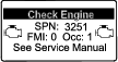
| Indication Level | Fault Code | Engine Power Rating | Recommended Action |
| Level 1: Engine Warning |  Check EngineSPN 3719, FMI 16 | The computer de-rates the engine power to 85%. | Perform a parked regeneration as soon as possible; refer to Performing a Parked or Recovery Regeneration. |
| Level 2: Engine Warning | 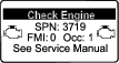 Check EngineSPN 3719, FMI 0 | The computer de-rates the engine power to 50%. | Perform a recovery regeneration as soon as possible; refer to Performing a Parked or Recovery Regeneration. |
DPF Ash Accumulation
-
The lighter ash is discharged through the exhaust system; the heavier ash collects in the soot filter.
-
Ash is a residue of the regeneration process. Over time, the diesel particulate filter accumulates ash that does not discharge with the engine exhaust.
-
The computer for the engine calculates the amount of ash accumulated in the DPF.
-
When enough ash accumulates, the engine computer sends information to the InfoCenter in the form of an engine fault to indicate the accumulation of ash in the DPF.
-
The fault messages indicate that it is time to service the DPF.
-
In addition to the warnings, the computer reduces the power produced by the engine at different ash-accumulation levels.
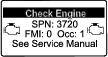
| Indication Level | Fault Code | Engine Speed Reduction | Engine Power Rating | Recommended Action |
|---|---|---|---|---|
| Level 1: Engine Warning | 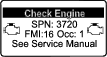 Check EngineSPN 3720, FMI 16 | None | The computer de-rates the engine power to 85%. | Service the DPF; refer to Performing a Parked or Recovery Regeneration |
| Level 2: Engine Warning | Check EngineSPN 3720, FMI 0 | None | The computer de-rates the engine power to 50%. | Service the DPF; refer to Parked or Recovery Regeneration |
Types of DPF Regeneration
| Type of Regeneration | Conditions that cause DPF regeneration | DPF description of operation |
|---|---|---|
| Passive | Occurs during normal operation of the machine at high-engine speed or high-engine load |
Refer to Passive DPF Regeneration . |
| Assist | Occurs because of low-engine speed, low-engine load, or after the computer detects the DPF is becoming obstructed with soot |
Refer to Assist DPF Regeneration. |
| Reset |
Occurs every 100 hours Also occurs after assist regeneration only if the computer detects that assist regeneration did not sufficiently reduce the soot level |
Refer to Reset Regeneration. |
| Type of Regeneration | Conditions that cause DPF regeneration | DPF description of operation |
|---|---|---|
| Parked | Occurs because the computer detects back pressure in the DPF due to soot buildup |
|
| Also occurs because the operator initiates a parked regeneration | ||
| May occur because you set the InfoCenter to inhibit reset regeneration and continued operating the machine, adding more soot when the DPF already needs a reset regeneration | ||
| May result from using the incorrect fuel or engine oil | ||
| Recovery | Occurs because the operator ignored requests for a parked regeneration and continued operating the machine, adding more soot to the DPF |
|
DPF Regeneration Menu
Accessing the DPF Regeneration Menu
-
Access the Service menu and scroll down to DPF REGENERATION.
-
Press the right button to access the DPF Regeneration menu.
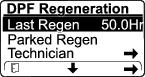
Time Since Last Regeneration
Access the DPF Regeneration menu and scroll down to the LAST REGEN field.
Use the LAST REGEN field to determine how many hours you have run the engine since the last reset, parked, or recovery regeneration.
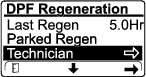
Technician Menu
Important: For operating convenience, you may decide to perform a parked regeneration before the soot load reaches 100%, provided the engine has run more than 50 hours since the last successful reset, parked, or recovery regeneration.
Use the technician menu to view the current state of engine regeneration control and view the reported soot level.
Access the DPF Regeneration menu, then scroll down and access the TECHNICIAN menu.
-
Use the DPF Operation Table to understand the current state of DPF operation.

DPF Operation Table
State Description Normal The DPF is in normal-operating mode—passive regeneration. Assist Regen The engine computer is performing an assist regeneration. Reset Stby The engine computer is trying to run a reset regeneration, but 1 of the following conditions prevents regeneration: The regen inhibit setting is set to ON. The exhaust temperature is too low for regeneration. Reset Regen The engine computer is running a reset regeneration. Parked Stby The engine computer is requesting that you run a parked regeneration. Parked Regen You initiated a parked regeneration request and the engine computer is processing the regeneration. Recov. Stby The engine computer is requesting that you run a recovery regeneration. Recov. Regen You initiated a recovery regeneration request and the engine computer is processing the regeneration. -
The soot load is measured as the percentage of soot in the DPF; refer to the soot-load table.
Note: The soot load value varies as the machine is operated and DPF regeneration occurs.
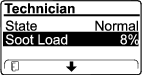
Soot-Load Table
Important Soot Load Values Regeneration State 0% to 5% Minimum soot load range 78% The engine computer performs an assist regeneration. 100% The engine computer automatically requests a parked regeneration. 122% The engine computer automatically requests a recovery regeneration.
Passive DPF Regeneration
-
Passive regeneration occurs as part of normal engine operation.
-
While operating the machine, run the engine at full-engine speed and high load when possible to promote DPF regeneration.
Assist DPF Regeneration
-
The engine computer adjusts engine settings to raise the exhaust temperature.
-
While operating the machine, run the engine at full engine speed and high load when possible to promote DPF regeneration.
Reset Regeneration
Caution
The exhaust temperature is hot (approximately 600°C (1,112°F) during DPF regeneration. Hot exhaust gas can harm you or other people.
-
Never operate the engine in an enclosed area.
-
Make sure that there are no flammable materials around the exhaust system.
-
Never touch a hot exhaust system component.
-
Never stand near or around the exhaust pipe of the machine.
-
The high exhaust-temperature icon
 displays in the InfoCenter
while the reset regeneration is processing.
displays in the InfoCenter
while the reset regeneration is processing. -
The engine computer adjusts engine settings to raise the exhaust temperature.
Important: The high exhaust-temperature icon indicates that the exhaust temperature discharged from of your machine may be hotter than during regular operation.
-
While operating the machine, run the engine at full engine speed and high load when possible to promote DPF regeneration.
-
Whenever possible, do not shut off the engine or reduce engine speed while the reset regeneration is processing.
Important: Whenever possible, allow the machine to complete the reset regeneration process before shutting off the engine.
Periodic Reset Regeneration
If the engine has not completed a successful Reset, Parked, or Recovery regeneration in the previous 100 hours of engine operation, the engine computer will attempt to perform a reset regeneration.
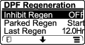
Setting the Inhibit Regen
Reset Regeneration Only

A reset regeneration produces the elevated engine exhaust temperatures. If you are operating the machine around trees, brush, tall grass, or other temperature-sensitive plants or materials, you can use the Inhibit Regen setting to prevent the engine computer from performing a reset regeneration.
Important: When you shut off the engine and start it again, the Inhibit Regen setting defaults to OFF.
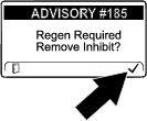
Note: If you set the InfoCenter to inhibit regeneration, the InfoCenter displays ADVISORY #185 every 15 minutes while the engine requests a reset regeneration.
-
Access the DPF Regeneration menu and scroll down to INHIBIT REGEN .

-
Press the right button to change the inhibit regeneration setting to ON or OFF.
Allowing a Reset Regeneration
The InfoCenter displays the high exhaust-temperature icon when the reset regeneration
is in process.
Note: If Inhibit Regen is set to ON, the InfoCenter displays ADVISORY #185 . Press the right button to set inhibit regeneration setting to OFF and continue with the reset regeneration.
Note: If the InfoCenter displays ADVISORY #186, set the engine to full throttle (high idle) to allow the reset regeneration to continue.

Note: When the reset regeneration completes, the high exhaust-temperature
icon disappears
from the InfoCenter screen.
Parked or Recovery Regeneration
-
When the engine computer requests either a parked regeneration or a recovery regeneration, the regeneration request icon
 displays
in the InfoCenter.
displays
in the InfoCenter. -
The machine does not automatically perform a parked regeneration or a recovery regeneration, you must run the regeneration through the InfoCenter.
Parked Regeneration Messages
When the engine computer requests a parked regeneration, the following messages display in the InfoCenter:
-
Engine warning SPN 3720, FMI 16
-
ADVISORY #188 Parked regeneration required
Note: Advisory #188 displays every 15 minutes.

Recovery Regeneration Messages
When the engine computer requests a recovery regeneration, the following messages display in the InfoCenter:
Engine warning SPN 3719, FMI 0
Refer to the Service Manual or your Authorized Service Dealer for details.
DPF Status-Limitation
-
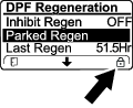
If the engine computer requests a parked regeneration or is processing a parked regeneration, the PARKED REGEN option locks and the lock icon appears on the screen.
-
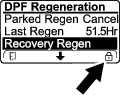
If the engine computer requests a recovery regeneration or is processing a recovery regeneration, the RECOVERY REGEN option locks and the lock icon appears on the screen.
Performing a Parked or Recovery Regeneration
Caution
The exhaust temperature is hot (approximately 600°C (1,112°F) during DPF regeneration. Hot exhaust gas can harm you or other people.
-
Never operate the engine in an enclosed area.
-
Make sure that there are no flammable materials around the exhaust system.
-
Never touch a hot exhaust system component.
-
Never stand near or around the exhaust pipe of the machine.
Important: The computer of the machine cancels DPF regeneration if you increase the engine speed from low idle or release the parking brake.
-
Ensure that the machine has at least the specified amount fuel in the tank for the type of regeneration you are performing:
-
Parked Regeneration: 1/4 tank of fuel
-
Recovery Regeneration: 1/2 tank of fuel
-
-
Park the machine on a level surface, in an area outside away from combustible materials.
-
Engage the parking brake and lower the loader arms.
-
Set the throttle to the low IDLE position.
-
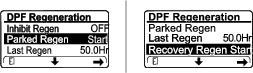
In the DPF Regeneration menu, scroll to PARKED REGEN START or RECOVERY REGEN START. Press the right button to start the regeneration.
-
When prompted, verify that you have that the fuel level is sufficient, as indicated in step 1. Press the right button to continue.

-
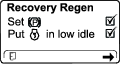
At the DPF checklist screen, verify that the parking brake is engaged and the engine speed is set to low idle. Press the right button to continue
-
At the INITIATE DPF REGEN screen, press the right button to continue.

-
The InfoCenter displays the INITIATING DPF REGEN message.

-
The InfoCenter displays the time to complete message.
-
Parked regeneration requires up to 30 minutes to complete.
-
Recovery regeneration requires up to 3 hours to complete.
Note: If you must cancel the regeneration after it is initiated, refer to Canceling a Parked or Recovery Regeneration.


-
-
The engine computer checks the engine state and fault information. The InfoCenter may display the following messages:
Message Corrective Action 
Exit the regeneration menu and run the machine until the time since last regeneration is greater than 50 hours; refer to Time Since Last Regeneration. 
Troubleshoot the engine fault and retry DPF regeneration. 
Start and run the engine. 
Run the engine to warm the coolant temperature to 60°C (140°F). 
Change the engine speed to low idle. 
Troubleshoot the engine computer condition and retry DPF regeneration. -
The InfoCenter displays the home screen and the regeneration acknowledge icon
 appears in the lower right corner of the screen as the regeneration
processes.
appears in the lower right corner of the screen as the regeneration
processes.Note: While the DPF regeneration runs, the InfoCenter displays the high exhaust-temperature icon
. -
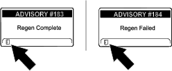
When the engine computer completes a parked or recovery regeneration, the InfoCenter displays ADVISORY #183; if it fails, the InfoCenter displays ADVISORY #184. Press the left button to exit to the home screen.
Canceling a Parked or Recovery Regeneration
-
In the DPF Regeneration menu, scroll to PARKED REGEN CANCEL or RECOVERY REGEN CANCEL.
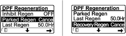
-
Press the right button to cancel the regeneration.
After Operation
After Operation Safety
General Safety
-
Engage the parking brake (if equipped), lower the loader arms, shut off the engine, remove the key, wait for all movement to stop, and allow the machine to cool before adjusting, cleaning, storing, or servicing it.
-
Clean debris from the attachments, drives, mufflers, and engine to help prevent fires. Clean up oil or fuel spills.
-
Keep all parts in good working condition and all hardware tightened.
-
Do not touch parts that may be hot from operation. Allow them to cool before attempting to maintain, adjust, or service the machine.
-
Use care when loading or unloading the machine into a trailer or truck.
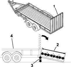
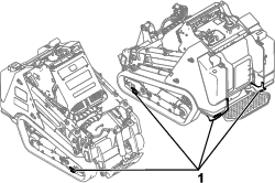
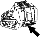
Retrieving a Stuck Machine
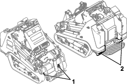
If the machine becomes stuck (e.g., in muddy conditions), pull the machine back into a stable position using either both front lift points or both rear tie-down points simultaneously.
Important: Do not use the front tie-down points to pull the machine.
Moving a Non-Functioning Machine
Important: Do not tow or pull the machine without first opening the tow valves, or you will damage the hydraulic system.
-
Shut off the engine and remove the key.
-
Remove the bottom plate; refer to Removing the Bottom Plate.
-
For each drive motor, remove the cap.
-
Lubricate a washer (M12) with oil on both sides.
-
Thread a nut (M12) onto a screw (M12), then install the screw through the washer and bypass tool into the brake piston. Do not overtighten.
-
Tighten the nut to release the brake.
-
Remove the front cover; Removing the Front Cover.
-
Turn the tow valves under the hydraulic pumps twice counterclockwise.
-
Tow the machine as required using the points described in Retrieving a Stuck Machine.
-
After repairing the machine, close the tow valves before operating it.
-
Install the front cover.
-
Remove the fasteners and bypass tool from each drive motor and install the cap.
-
Install the bottom plate.
Hauling the Machine
Use a heavy-duty trailer or truck to haul the machine. Use a full-width ramp. Ensure that the trailer or truck has all the necessary brakes, lighting, and marking as required by law. Please carefully read all the safety instructions. Knowing this information could help you or bystanders avoid injury. Refer to your local ordinances for trailer and tie-down requirements.
Warning
Driving on the street or roadway without turn signals, lights, reflective markings, or a slow-moving-vehicle emblem is dangerous and can lead to accidents causing personal injury.
Do not drive the machine on a public street or roadway.
Selecting a Trailer
Warning
Loading or unloading a machine onto a trailer or truck increases the possibility of tip-over and could cause serious injury or death (Figure 53).
-
Use only full-width ramps.
-
Ensure that the length of ramp is at least 4 times as long as the height of the trailer or truck bed to the ground. This ensures that ramp angle does not exceed 15 degrees on flat ground.
Loading the Machine
Warning
Loading or unloading a machine onto a trailer or truck increases the possibility of tip-over and could cause serious injury or death.
-
Use extreme caution when operating a machine on a ramp.
-
Load and unload the machine with the heavy end up the ramp.
-
Avoid sudden acceleration or deceleration while driving the machine on a ramp as this could cause a loss of control or a tip-over situation.
-
If using a trailer, connect it to the towing vehicle and connect the safety chains.
-
If applicable, connect the trailer brakes.
-
Lower the ramp(s).
-
Lower the loader arms.
-
Load the machine onto the trailer with the heavy end up the ramp, carrying loads low.
-
If the machine has a full load-bearing attachment (e.g., bucket) or a non-load-bearing attachment (e.g., trencher), drive the machine forward up the ramp.
-
If the machine has an empty load-bearing attachment or no attachment, back the machine up the ramp.

-
-
Lower the loader arms all the way down.
-
Engage the parking brake, shut off the engine, and remove the key.
-
Use the metal tie-down loops on the machine to securely fasten the machine to the trailer or truck with straps, chains, cable, or ropes. Refer to local regulations for tie-down requirements.
Important: Do not use the tie-down loops to lift the machine.
Unloading the Machine
-
Lower the ramp(s).
-
Unload the machine from the trailer with the heavy end up the ramp, carrying loads low.
-
If the machine has a full load-bearing attachment (e.g., bucket) or a non-load-bearing attachment (e.g., trencher), back it down the ramp.
-
If the machine has an empty load-bearing attachment or no attachment, drive it forward down the ramp.

-
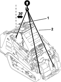
Lifting the Machine
Remove any attachments and lift the machine using the 4 lift points.
Do not exceed a 30-degree angle when lifting the machine; use the minimum chain lengths provided below.
Maintenance
Note: Determine the left and right sides of the machine from the normal operating position.
Maintenance Safety
Caution
If you leave the key in the switch, someone could accidently start the engine and seriously injure you or other bystanders.
Remove the key from the switch before you perform any maintenance.
-
Park the machine on a level surface, disengage the auxiliary hydraulics, lower the attachment, engage the parking brake (if equipped), shut off the engine, and remove the key. Wait for all movement to stop and allow the machine to cool before adjusting, cleaning, storing, or repairing it.
-
Clean up oil or fuel spills.
-
Do not allow untrained personnel to service the machine.
-
Use jack stands to support the components when required.
-
Carefully release pressure from components with stored energy; refer to Relieving Hydraulic Pressure.
-
Disconnect the battery before making any repairs; refer to Using the Battery-Disconnect Switch.
-
Keep your hands and feet away from the moving parts. If possible, do not make adjustments with the engine running.
-
Keep all parts in good working condition and all hardware tightened. Replace all worn or damaged decals.
-
Do not tamper with the safety devices.
-
Attachments can change the stability and the operating characteristics of the machine.
-
Use only genuine Toro replacement parts.
-
If any maintenance or repair requires the loader arms to be in the raised position, secure the arms in the raised position with the hydraulic-cylinder lock(s).
-
Refer to local regulations for safely maintaining the machine and attach a warning tag to the control panel to inform others of ongoing maintenance.
Recommended Maintenance Schedule(s)
| Maintenance Service Interval | Maintenance Procedure |
|---|---|
| After the first 8 hours |
|
| After the first 50 hours |
|
| Before each use or daily |
|
| Every 25 hours |
|
| Every 50 hours |
|
| Every 100 hours |
|
| Every 250 hours |
|
| Every 400 hours |
|
| Every 500 hours |
|
| Every 800 hours |
|
| Every 1,000 hours |
|
| Every 1,500 hours |
|
| Every 3,000 hours |
|
| Yearly or before storage |
|
| Every 2 years |
|
Important: Refer to your engine owner’s manual for additional maintenance procedures.
Pre-Maintenance Procedures
Using the Cylinder Locks
Warning
The loader arms may lower when in the raised position, crushing anyone under them.
Install the cylinder lock(s) before performing maintenance that requires raised loader arms.
Installing the Cylinder Locks
-
Remove the attachment.
-
Raise the loader arms to the fully raised position.
-
Shut off the engine and remove the key.
-
Loosen the knob securing the cylinder lock to the loader arm.
-
Slide the cylinder lock over the lift-cylinder rod.
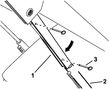
-
Repeat step 4 and 6 for the other side of the machine.
-
Slowly lower the loader arms until the cylinder locks contact the cylinder bodies and rod ends.
Removing and Storing the Cylinder Locks
Important: Remove the cylinder locks from the rods and fully secure them in the storage position before operating the machine.
-
Start the engine.
-
Raise the loader arms to the fully raised position.
-
Shut off the engine and remove the key.
-
Remove the pins securing the cylinder locks.
-
Remove the cylinder locks from the lift-cylinder rods.
-
Insert the pins into the locks.
-
Place the cylinder locks on the loader arms, with the pin rings beneath the locks, and secure each lock using the hand knob.
-
Lower the loader arms.
Accessing Internal Components
Warning
Opening or removing covers, hoods, and screens while the engine is running could allow you to contact moving parts, seriously injuring you.
Before opening any of the covers, hoods, and screens, shut off the engine, remove the key from the key switch, and allow the engine to cool.
Opening the Hood
-
Park the machine on a level surface, engage the parking brake, and lower the loader arms.
-
Shut off the engine, remove the key, and allow the engine to cool.
-
Unlock the hood using the latch key and press the button to release the latch.
-
Lift open the hood.
Closing the Hood
-
Lower the hood.
-
Press down the latch to secure the hood.
-
Lock the hood using the latch key.
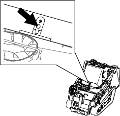
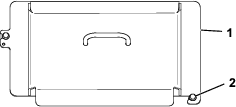
Removing the Rear Cover
-
Remove the 2 bolts securing the top of the rear cover.
-
Lift the cover out of the slots in radiator bracket.
Removing the Bottom Plate
-
Remove the 2 bolts securing the bottom plate.
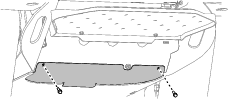
-
Remove the bottom plate.
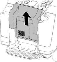
Removing the Front Cover
-
Raise the loader arms and secure them with the cylinder locks.
-
Loosen the 2 bolts securing the front cover to the machine.
-
Slide the cover off the machine.
-
When installing the cover, torque the bolts to 41 N∙m (30 ft-lb).
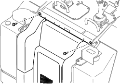
Removing the Front Cover Assembly
-
Raise the loader arms and secure them with the cylinder locks.
-
Open the hood.
-
Remove the 4 bolts securing the cover assembly to the machine.
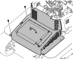
-
Remove the cover assembly.
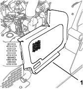
Removing the Side Screens
-
Open the hood.
-
Slide the screen out of the front and rear slots.
Lubrication
Greasing the Machine
| Maintenance Service Interval | Maintenance Procedure |
|---|---|
| Before each use or daily |
|
Grease Type: General-purpose grease.
-
Park the machine on a level surface, lower the loader arms, and engage the parking brake.
-
Shut off the engine and remove the key.
-
Clean the grease fittings with a rag.
-
Connect a grease gun to each fitting.
-
Pump grease into the fittings until grease begins to ooze out of the bearings (approximately 3 pumps).
-
Wipe up any excess grease.
Engine Maintenance
Engine Safety
-
Shut off the engine before checking the oil or adding oil to the crankcase.
-
Do not change the engine governor setting or overspeed the engine.
-
Keep your hands, feet, face, other body parts, and clothing away from the muffler and other hot surfaces.
Servicing the Air Cleaner
| Maintenance Service Interval | Maintenance Procedure |
|---|---|
| Before each use or daily |
|
| Every 100 hours |
|
| Every 500 hours |
|
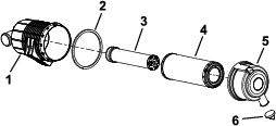
Checking the Air Cleaner
-
Park the machine on a level surface, engage the parking brake, and lower the loader arms.
-
Shut off the engine and remove the key.
-
Open the hood.
-
Check the air-cleaner body for damage, which could possibly cause an air leak.
Replace a damaged air-cleaner body.
-
Check the air-intake system for leaks, damage, or loose hose clamps.
-
Service the air-cleaner filter and safety element when alerted.
Important: Do not over-service the air filter.
-
Ensure that the cover seats correctly and seals with the air-cleaner body.
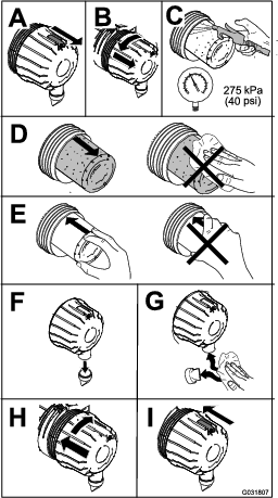
Servicing the Air Cleaner
Note: If the foam gasket in the cover is damaged, replace it.
Important: Avoid using high-pressure air, which could force dirt through the filter into the intake tract.
Important: Do not clean the used filter to avoid damaging the filter media.
Important: Do not use a damaged filter.
Important: Do not apply pressure to the flexible center of the filter.
Servicing the Engine Oil
| Maintenance Service Interval | Maintenance Procedure |
|---|---|
| After the first 50 hours |
|
| Before each use or daily |
|
| Every 250 hours |
|
Engine-Oil Specifications
The engine ships with oil in the crankcase; however, check the oil level before and after you first start the engine.
Crankcase capacity: 5.2 L (5.5 US Qt) with the filter
Preferred engine oil: Toro Premium Engine Oil
If using an alternate oil, use high-quality, low-ash engine oil that meets or exceeds the following specifications:
-
API service category CJ-4 or higher
-
ACEA service category E6
-
JASO service category DH-2
Important: Using engine oil other than API classification CJ-4 or higher, ACEA E6, or JASO DH-2 may cause the diesel particulate filter to plug or cause engine damage.
Use the following engine oil viscosity grade:
-
SAE 10W-30 or 5W-30 (all temperatures)
-
SAE 15W-40 (above 0° F)
Note: Toro Premium Engine oil is available from your Authorized Service Dealer.
Checking the Engine-Oil Level
-
Park the machine on a level surface, engage the parking brake, and lower the loader arms.
-
Shut off the engine, remove the key, and allow the engine to cool.
-
Open the hood.
-
Remove the left side screen.
-
Clean the area around the oil dipstick and oil-fill cap.
-
Check the oil and add additional oil as needed.
Important: Do not overfill the crankcase with oil; if the oil in the crankcase is too high and you run the engine, you may damage the engine.
-
Close the hood.
Changing the Engine Oil and Filter
-
Remove any attachments.
-
Start the engine and let it run for 5 minutes.
Note: This warms the oil so that it drains better.
-
Park the machine on a level surface and engage the parking brake.
-
Raise the loader arms and install the cylinder locks.
-
Shut off the engine and remove the key.
-
Drain the oil beneath the platform.
Caution
Components will be hot if the machine has been running. If you touch hot components, you may be burned.
Use care to avoid touching hot components while changing the oil and/or filter.
-
Torque the drain plug to 46 to 56 N∙m (34 to 42 ft-lb).
-
Open the hood.
-
Remove the left screen; refer to Removing the Side Screens.
-
Place a shallow pan or rag under the filter to catch oil.
-
Change the oil filter.
-
Remove the oil-fill cap and slowly pour approximately 80% of the specified amount of oil in through the valve cover.
-
Check the oil level.
-
Slowly add additional oil to bring the level to the upper hole on the dipstick.
-
Replace the fill cap.
-
Install the left screen.
-
Close the hood.
Note: Dispose of the used oil at a certified recycling center.
Servicing the Diesel-Oxidation Catalyst (DOC) and the Soot Filter
| Maintenance Service Interval | Maintenance Procedure |
|---|---|
| Every 3,000 hours |
|
If engine faults , , or display in the InfoCenter, clean the soot filter using the steps that follow:
-
Refer to the Engine section in the Service Manual for information on disassembling and assembling the diesel-oxidation catalyst and the soot filter of the DPF.
-
Refer to your Authorized Service Dealer for diesel-oxidation catalyst and the soot filter replacement parts or service.
-
Contact your Authorized Service Dealer to reset the engine ECU after you install a clean DPF.
Fuel System Maintenance
Danger
In certain conditions, fuel is extremely flammable and highly explosive. A fire or explosion from fuel can burn you and others and can damage property.
Refer to Fuel Safety for a complete list of fuel related precautions.
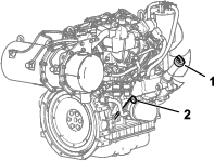
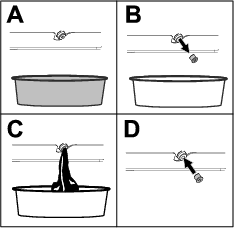
Draining the Water Separator
| Maintenance Service Interval | Maintenance Procedure |
|---|---|
| Every 50 hours |
|
-
Park the machine on a level surface, engage the parking brake, and lower the loader arms.
-
Shut off the engine and remove the key.
-
Place a container under the water separator.
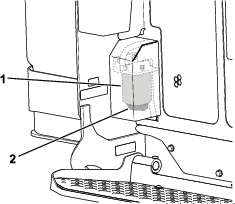
-
Loosen the drain valve on the bottom of the filter canister and allow the water to drain.
-
Tighten the drain valve.
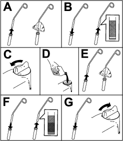
Replacing the Water Separator Filter
| Maintenance Service Interval | Maintenance Procedure |
|---|---|
| Every 500 hours |
|
-
Park the machine on a level surface, engage the parking brake, and lower the loader arms.
-
Shut off the engine and remove the key.
-
Remove the rear cover; refer to Removing the Rear Cover.
-
Clean the area where the water separator filter mounts.
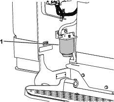
-
Remove the filter canister and clean the mounting surface
-
Lubricate the gasket on the new filter canister with clean oil.
-
Fill the canister with fuel.
-
Install the filter canister by hand until the gasket contacts the mounting surface, then rotate it an additional 1/2 turn.
-
Install the rear cover.
Checking the Fuel Lines and Connections
| Maintenance Service Interval | Maintenance Procedure |
|---|---|
| Every 400 hours |
|
Inspect the fuel lines and connections for deterioration, damage, or loose connections. Tighten any loose connections and contact your Authorized Service Dealer for assistance in fixing damaged fuel lines.
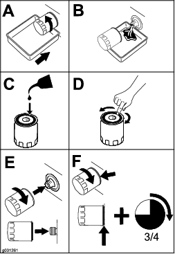
Replacing the Fuel Filter
| Maintenance Service Interval | Maintenance Procedure |
|---|---|
| Every 500 hours |
|
-
Park the machine on a level surface, engage the parking brake, and lower the loader arms.
-
Shut off the engine and remove the key.
-
Open the hood.
-
Clean the area where the fuel filter mounts.
-
Remove the filter canister and clean the mounting surface.
-
Lubricate the gasket on the new filter canister with clean oil.
-
Install the filter canister by hand until the gasket contacts the mounting surface, then rotate it an additional 1/2 turn.
-
Bleed the fuel system; refer to Bleeding the Fuel System.
-
Start the engine and check for fuel leaks around the filter head.
-
Close the hood.
Bleeding the Fuel System
You must bleed the fuel system before starting the engine if any of the following situations have occurred:
-
Initial startup of a new machine
-
The engine has ceased running due to a lack of fuel.
-
Maintenance has been performed upon fuel-system components (e.g., filter replaced).
-
Turn the key to the RUN position.
-
Let the fuel pump run for 2 minutes prior to starting the machine.
Draining the Fuel Tank(s)
| Maintenance Service Interval | Maintenance Procedure |
|---|---|
| Every 500 hours |
|
Have an Authorized Service Dealer drain and clean the fuel tank(s).
Electrical System Maintenance
Electrical System Safety
-
Disconnect the battery before making any repairs; refer to Using the Battery-Disconnect Switch.
-
Charge the battery in an open, well-ventilated area, away from sparks and flames. Unplug the charger before connecting or disconnecting the battery. Wear protective clothing and use insulated tools.
-
Battery acid is poisonous and can cause burns. Avoid contact with skin, eyes, and clothing. Protect your face, eyes, and clothing when working with a battery.
-
Battery gases can explode. Keep cigarettes, sparks, and flames away from the battery.
Using the Battery-Disconnect Switch
-
Park the machine on a level surface, engage the parking brake, and lower the loader arms.
-
Shut off the engine and remove the key.
-
Open the hood.
-
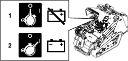
Turn the battery-disconnect switch to the ON or OFF position to perform the following:
-
To energize the machine electrically, rotate the battery-disconnect switch clockwise to the ON position.
-
To de-energize the machine electrically, rotate the battery-disconnect switch counterclockwise to the OFF position.
-
Servicing the Battery
| Maintenance Service Interval | Maintenance Procedure |
|---|---|
| Every 50 hours |
|
Removing the Battery
Warning
Incorrect battery cable routing could damage the machine and cables, causing sparks. Sparks can cause the battery gasses to explode, resulting in personal injury.
Always disconnect the negative (black) battery cable before disconnecting the positive (red) cable.
-
Remove any attachments.
-
Park the machine on a level surface and engage the parking brake.
-
Raise the loader arms and install the cylinder locks.
-
Shut off the engine and remove the key.
-
Remove the front cover assembly; refer to Removing the Front Cover Assembly.
-
Disconnect the negative (black) ground cable from the battery post. Retain the fasteners.
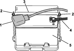
-
Slide the rubber cover off the positive (red) cable.
-
Disconnect the positive (red) cable from the battery post. Retain the fasteners.
-
Remove the wing nuts, rods, and strap.
-
Remove the battery.
Charging the Battery
Warning
Charging the battery produces gasses that can explode.
Never smoke near the battery and keep sparks and flames away from battery.
Important: Always keep the battery fully charged (1.265 specific gravity). This is especially important to prevent battery damage when the temperature is below 0°C (32°F).
-
Remove the battery from the machine; refer to Removing the Battery.
-
Charge the battery for 4 to 8 hours at a rate of 3 to 4 A. Do not overcharge the battery.
-
When the battery is fully charged, unplug the charger from the electrical outlet, then disconnect the charger leads from the battery posts.
Cleaning the Battery
Note: Keep the terminals and the entire battery case clean to help extend battery life.
-
Park the machine on a level surface, engage the parking brake (if equipped), and lower the loader arms.
-
Shut off the engine and remove the key.
-
Remove the battery from the machine; Removing the Battery.
-
Wash the entire case with a solution of baking soda and water.
-
Rinse the battery with clear water.
-
Coat the battery posts and cable connectors with Grafo 112X (skin-over) grease or petroleum jelly to prevent corrosion.
-
Install the battery; refer to Installing the Battery.
Installing the Battery
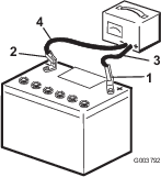
Warning
Incorrect battery cable routing could damage the machine and cables, causing sparks. Sparks can cause the battery gasses to explode, resulting in personal injury.
Always connect the positive (red) battery cable before connecting the negative (black) cable.
-
Place the battery on the battery tray and secure it with the strap, wing nuts, and rods.
-
Using the fasteners previously removed, install the positive (red) battery cable to the positive (+) battery terminal.
-
Slide the red terminal boot onto the positive battery post.
-
Using the fasteners previously removed, install the negative (black) battery cable to the negative (-) battery terminal.
-
Install the front cover assembly.
Servicing a Replacement Battery
The original battery is maintenance-free and does not require service. For servicing a replacement battery, refer to the battery manufacturer’s instructions.
Jump-Starting the Machine
Warning
Jump-starting the battery can produce gasses that can explode.
Do not smoke near the battery, and keep sparks and flames away from battery.
-
Remove the front cover; refer to Removing the Front Cover.
-
Check and clean corrosion from the battery terminals before jump-starting. Ensure that the connections are tight.
Caution
Corrosion or loose connections can cause unwanted electrical voltage spikes at any time during the jump-starting procedure.
Do not attempt to jump-start the machine with loose or corroded battery terminals, or damage to the engine may occur.
Danger
Jump-starting a weak battery that is cracked or frozen or has a low electrolyte level or an open/shorted battery cell can cause an explosion, resulting in serious personal injury.
Do not jump-start a weak battery if these conditions exist.
-
Make sure that the booster battery is a good and fully charged lead-acid battery at 12.6 V or greater.
Note: Use properly sized jumper cables with short lengths to reduce voltage drop between systems. Make sure that the cables are color coded or labeled for the correct polarity.
Warning
Batteries contain acid and produce explosive gases.
-
Shield your eyes and face from the batteries at all times.
-
Do not lean over the batteries.
Note: Ensure that the vent caps are tight and level. Place a damp cloth, if available, over any vent caps on both batteries. Also ensure that the machines do not touch and that both electrical systems are off and at the same rated system voltage. These instructions are for negative ground systems only.
-
-
Connect the positive (+) cable to the positive (+) terminal of the discharged battery that is wired to the starter or solenoid as shown in Figure 83.
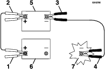
-
Connect the other end of the positive (+) jumper cable to the positive terminal of the battery in the other machine.
-
Connect an end of the negative (-) jumper cable to the negative post of the battery in the other machine.
-
Connect the other end of the negative (-) jumper cable to a ground point, such as an unpainted bolt or chassis member.
-
Start the engine in the other machine. Let it run a few minutes, then start your engine.
-
Remove the cables in the reverse order of connection.
-
Install the front cover.
Servicing the Fuses
The electrical system is protected by fuses. It requires no maintenance; however, if a fuse blows, check the component/circuit for a malfunction or a short.
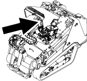
| 1 | 2 | 3 | 4 | 5 | 6 | 7 | 8 | 9 | 10 | 11 | 12 | |
| A | X | X | Joystick | Attachment Power | Accessory | Tec Power | Horn | |||||
| (5 A) | (20 A) | (10 A) | (7.5 A) | (10 A) | ||||||||
| B | X | X | X | X | TDM 2002 | Auto Level | Tec Power | Lights/USB | ||||
| (10 A) | (10 A) | (7.5 A) | (15 A) | |||||||||
| C | X | X | X | X | Telematics | X | X | Tec Power | System Power | |||
| (10 A) | (7.5 A) | (15 A) | ||||||||||
| D | X | X | X | (Relay) | (Relay) | (Relay) | ||||||
| E | X | X | X | |||||||||
Note: If the machine does not start, either the main circuit or the control panel/relay fuse could be blown.
Drive System Maintenance
Servicing the Tracks
| Maintenance Service Interval | Maintenance Procedure |
|---|---|
| After the first 8 hours |
|
| After the first 50 hours |
|
| Before each use or daily |
|
| Every 50 hours |
|
Cleaning the Tracks
-
Park the machine on a level surface and engage the parking brake.
-
With the bucket installed and angled downward, lower it into the ground so that the front of the traction unit lifts off the ground a few centimeters (inches).
-
Shut off the engine and remove the key.
-
Using a water hose or pressure washer, remove dirt from each track system.
Important: Ensure that you use high-pressure water to wash only the track area. Do not use a high-pressure washer to clean the rest of the traction unit. Do not use high pressure water between the drive sprocket and the traction unit or you may damage the motor seals. High-pressure washing can damage the electrical system and hydraulic valves or deplete grease.
Important: Ensure that you fully clean the road wheels, front wheel, rear wheel, and drive sprocket. The road wheels should rotate freely when clean.
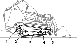
Checking and Adjusting the Track Tension
Lift/support 1 side of the machine and using the weight of the track, verify that the gap between the bottom of the lip of the road wheel and the track is 19 mm (3/4 inch). If it is not, adjust the track tension using the following procedure.
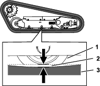
-
Park the machine on a level surface, engage the parking brake, and lower the loader arms.
-
Shut off the engine and remove the key.
-
Raise the side of the machine that you are adjusting so that the track is off the ground.
-
Loosen the bolts on the rear cover and remove the cover.
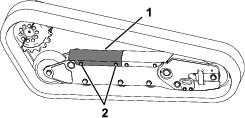
-
Loosen the jam nut and turn the tensioning screw clockwise until the track deflection is 19 mm (3/4 inch).
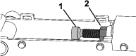
-
Tighten the jam nut.
-
Install the cover and tighten the bolts.
-
Repeat the procedure for the other track.
-
Drive the machine, then park the machine on a level surface, engage the parking brake, shut off the engine, and remove the key.
-
Verify that the track deflection is 19 mm (3/4 inch). Adjust if necessary.
Replacing the Tracks
Removing the Tracks
-
Remove any attachments.
-
Park the machine on a level surface, ensuring that only 1 sprocket half is engaged with the track.
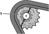
-
Lower the loader arms.
-
Shut off the engine and remove the key.
-
Raise the machine off the ground so that the bottom of the track is at least 10.2 cm (4 inches) off the ground. Support the machine using jack stands.
Note: Use jack stands rated for your machine.
Warning
Mechanical or hydraulic jacks may fail to support the machine and cause serious injury.
Use jack stands when supporting the machine.
-
Loosen the bolts on the rear cover and remove the cover.
-
Loosen the jam nut and turn the tensioning screw to release the tension.
-
Remove the segment of the drive sprocket not engaged with the track.
Important: If you do not remove the sprocket segment, it may be difficult to install a new track without damaging it.
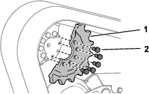
-
Start the machine and disengage the parking brake.
-
Move the traction control forward until the other half of the drive sprocket is not engaged with the track
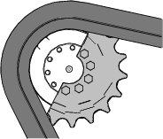
-
Shut off the engine and remove the key.
-
Remove the track from the track frame, drive hub, then front wheel.
Installing the Tracks
-
Wrap the new track around the front wheel.
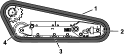
-
Push the track under and between the road wheels and wrap it around the rear wheel.
-
Start the engine and disengage the parking brake.
-
Move the traction control forward until the drive sprocket half engages with the track.
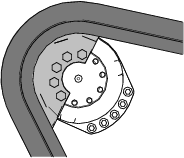
-
Shut off the engine and remove the key.
-
Apply thread-locking compound to the bolts of the drive sprocket half that you removed and install the other sprocket half. Torque the bolts to 80 to 99 N∙m (59 to 73 ft-lb).
-
Adjust the tensioning screw until the track deflection is 19 mm (3/4 inch).
-
Tighten the jam nut.
-
Install the cover and tighten the bolts.
-
Repeat the procedure to replace the other track.
-
Lower the machine to the ground.
-
Drive the machine, then park the machine on a level surface, engage the parking brake, shut off the engine, and remove the key.
-
Verify that the track tension is correct; refer to Checking and Adjusting the Track Tension.
Cooling System Maintenance
Cooling System Safety
-
Swallowing engine coolant can cause poisoning; keep out of reach from children and pets.
-
Discharge of hot, pressurized coolant or touching a hot radiator and surrounding parts can cause severe burns.
-
Always allow the engine to cool at least 15 minutes before removing the radiator cap.
-
Use a rag when opening the radiator cap, and open the cap slowly to allow steam to escape.
-
Servicing the Cooling System
| Maintenance Service Interval | Maintenance Procedure |
|---|---|
| Before each use or daily |
|
| Every 100 hours |
|
Cleaning the Radiator Screen
| Maintenance Service Interval | Maintenance Procedure |
|---|---|
| Before each use or daily |
|
Remove any buildup of grass, dirt or other debris from the radiator screen with compressed air.
Checking the Engine-Coolant Level
| Maintenance Service Interval | Maintenance Procedure |
|---|---|
| Before each use or daily |
|
The cooling system is filled with a 50/50 solution of water and permanent ethylene-glycol antifreeze.
-
Park the machine on a level surface, lower the loader arms, engage the parking brake, and shut off the engine.
-
Remove the key from the key switch and allow the engine to cool.
-
Open the hood.
-
Check the coolant level in the expansion tank.
Note: The coolant level should be at or above the mark on the side of the tank.
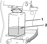
-
If the coolant level is low, remove the expansion tank cap and add a 50/50 mixture of water and permanent ethylene-glycol antifreeze.
Important: Do not overfill the expansion tank.
-
Install the expansion-tank cap.
Changing the Engine Coolant
| Maintenance Service Interval | Maintenance Procedure |
|---|---|
| Every 800 hours |
|
Have an Authorized Service Dealer change the engine coolant yearly.
If you need to add engine coolant, refer to Checking the Engine-Coolant Level.
Belt Maintenance
Checking the Alternator-Belt Tension
| Maintenance Service Interval | Maintenance Procedure |
|---|---|
| Every 100 hours |
|
-
Apply 44 N (10 lb) of force to the alternator belt, midway between the pulleys.
-
If the deflection is not 10 mm (3/8 inch), loosen the alternator mounting bolts.
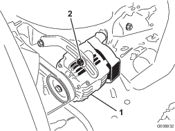
-
Increase or decrease the alternator-belt tension.
-
Tighten the mounting bolts.
-
Check the deflection of the belt again to ensure that the tension is correct.
Controls System Maintenance
Adjusting the Controls
The factory adjusts the controls before shipping the machine. However, after many hours of use, you may need to adjust the traction control alignment, the NEUTRAL position of the traction control, and the tracking of the traction control in the full forward position.
Contact your Authorized Service Dealer to adjust the controls of your machine.
Hydraulic System Maintenance
Hydraulic System Safety
-
Seek immediate medical attention if fluid is injected into skin. Injected fluid must be surgically removed within a few hours by a doctor.
-
Ensure that all hydraulic-fluid hoses and lines are in good condition and all hydraulic connections and fittings are tight before applying pressure to the hydraulic system.
-
Keep your body and hands away from pinhole leaks or nozzles that eject high-pressure hydraulic fluid.
-
Use cardboard or paper to find hydraulic leaks.
-
Safely relieve all pressure in the hydraulic system before performing any work on the hydraulic system.
Relieving Hydraulic Pressure
To relieve hydraulic pressure while the engine is on, disengage the auxiliary hydraulics and fully lower and retract the loader arms.
To relieve the pressure while the engine is off, cycle the joystick between the forward positions to lower the loader arms.
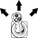
Hydraulic Fluid Specifications
| Maintenance Service Interval | Maintenance Procedure |
|---|---|
| Every 100 hours |
|
| Every 400 hours |
|
| Every 1,000 hours |
|
| Every 1,500 hours |
|
| Every 2 years |
|
Hydraulic-Tank Capacity: 44.7 L (11.8 US gallons)
Use only 1 of the following fluids in the hydraulic system:
-
Toro Premium Transmission/Hydraulic Tractor Fluid (refer to your Authorized Service Dealer for more information)
-
Toro PX Extended Life Hydraulic Fluid (refer to your Authorized Service Dealer for more information)
-
If either of the above Toro fluids are not available, you may use another Universal Tractor Hydraulic Fluid (UTHF), but they must be only conventional, petroleum-based products. The specifications must fall within the listed range for all the following material properties and the fluid should meet the listed industry standards. Check with your hydraulic fluid supplier to determine if the fluid meets these specifications.
Note: Toro will not assume responsibility for damage caused by improper substitutions, so use only products from reputable manufacturers who will stand behind their recommendations.
Material Properties Viscosity, ASTM D445 cSt at 40°C: 55 to 62 cSt at 100°C: 9.1 to 9.8 Viscosity index, ASTM D2270 140 to 152 Pour Point, ASTM D97 -37 to -43°C (-35 to -46°F) Industry Standards API GL-4, AGCO Powerfluid 821 XL, Ford New Holland FNHA-2-C-201.00, Kubota UDT, John Deere J20C, Vickers 35VQ25 and Volvo WB-101/BM Note: Many hydraulic fluids are almost colorless, making it difficult to spot leaks. A red dye additive for the hydraulic system fluid is available in 20 ml (2/3 fl oz) bottles. One bottle is sufficient for 15 to 22 L (4 to 6 US gallons) of hydraulic fluid. Order Part No. 44-2500 from your Authorized Toro Dealer.
Checking the Hydraulic-Fluid Level
| Maintenance Service Interval | Maintenance Procedure |
|---|---|
| Every 25 hours |
|
Important: Always use the correct hydraulic fluid. Unspecified fluids will damage the hydraulic system. Refer to Hydraulic Fluid Specifications.
-
Remove any attachments.
-
Park the machine on a level surface, engage the parking brake, and lower the loader arms.
-
Shut off the engine and remove the key.
-
Raise the bracket.
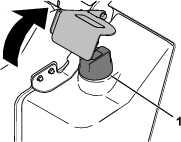
-
Clean the area around the filler cap .
-
Remove the filler-neck cap and check the fluid level on the dipstick.
Note: The fluid level should be within the marks on the dipstick.
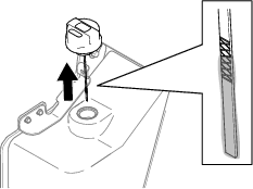
-
If the level is low, add enough fluid to raise it to the proper level.
-
Install the filler cap.
-
Lower the bracket.
Replacing the Hydraulic Filters
Important: Do not substitute an automotive oil filter; otherwise, severe hydraulic system damage may occur.
-
Remove any attachments.
-
Park the machine on a level surface and engage the parking brake.
-
Raise the loader arms and install the cylinder locks.
-
Shut off the engine, remove the key, and allow the engine to cool.
-
Remove the front cover; refer to Removing the Front Cover.
-
Place a drain pan under the filter and replace the filter.
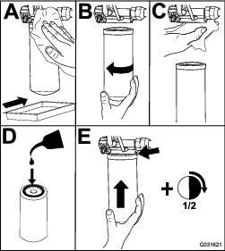
-
Clean up any spilled fluid.
-
Start the engine and let it run for about 2 minutes to purge air from the system.
-
Shut off the engine and check for leaks.
-
Check the fluid level in the hydraulic tank; refer toChecking the Hydraulic-Fluid Level and add fluid to raise the level to mark on dipstick.
Important: Do not overfill the tank.
-
Install the front cover.
-
Remove and store the cylinder locks and lower the loader arms.
Changing the Hydraulic Fluid
-
Park the machine on a level surface, engage the parking brake, and lower the loader arms.
-
Shut off the engine and remove the key.
-
Place a large drain pain capable of holding 57 L (15 US gallons) under the drain plug on the hydraulic tank.
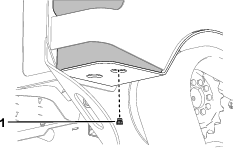
-
Remove the drain plug and allow the oil to drain into the pan.
-
When the oil is finished draining, install and tighten the drain plug.
Note: Dispose of the used oil at a certified recycling center.
-
Fill the hydraulic tank with hydraulic fluid; refer to Hydraulic Fluid Specifications.
-
Start the engine and let it run for a few minutes.
-
Shut off the engine and remove the key.
-
Check the hydraulic-fluid level and add fluid to fill the tank if necessary; refer to Checking the Hydraulic-Fluid Level.
Loader Maintenance
Torquing the Loader Arm Adjustment Screws
| Maintenance Service Interval | Maintenance Procedure |
|---|---|
| Every 25 hours |
|
Check the torque whenever the lower loader arms rattle.
-
Park the machine on a level surface.
-
Shut off the engine, remove the key, and allow the engine to cool.
-
On each loader arm, loosen the setscrew on the 4 adjustment screws.
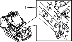
-
Torque the adjustment screws to 27 N∙m (20 ft-lb).
-
Check that the length of the adjustment screws that is protruding from the arms is equal side to side.
-
Apply medium-strength thread-locking compound to the setscrews and tighten them until they just contact the adjustment screws.
Important: Do not overtighten the setscrews; otherwise you may damage the adjustment screw threads.
Cleaning
Removing Debris
| Maintenance Service Interval | Maintenance Procedure |
|---|---|
| Before each use or daily |
|
Important: Operating the engine with blocked screens and/or cooling shrouds removed will result in engine damage from overheating.
-
Park the machine on a level surface and lower the loader arms.
-
Shut off the engine, remove the key, and allow the engine to cool.
-
Open the hood.
-
Clean any debris from the front and side screens.
-
Wipe away debris from the air cleaner.
-
Clean any debris buildup on the engine and in the oil cooler fins with a brush or blower.
Important: Operating the engine with blocked screens and/or cooling shrouds removed will result in engine damage due to overheating.
-
Clean debris from the hood opening, muffler, heat shields, and radiator screen (if applicable).
-
Close the hood.
Washing the Machine
When pressure washing the machine, do the following:
-
Wear appropriate personal protective equipment for the pressure washer.
-
Keep all guards in place on the machine.
-
Avoid spraying at electronic components.
-
Avoid spraying at edges of decals.
-
Spray the exterior of the machine only. Do not spray directly into openings in the machine.
-
Spray only the dirty parts of the machine.
-
Use a 40-degree or larger spray nozzle. 40-degree nozzles are usually white.
-
Keep the tip of the pressure washer at least 61 cm (2 ft) away from the surface being washed.
-
Use only pressure washers with pressure below 13790 kpa (2000 psi) and flow below 7.6 L (2 US gallons) per minute.
-
Replace damaged or peeling decals.
-
Grease all grease points after washing; refer to Greasing the Machine.
Cleaning the Chassis
| Maintenance Service Interval | Maintenance Procedure |
|---|---|
| Every 100 hours |
|
Over time, the chassis under the engine collects dirt and debris that must be removed. Open the hood and use a flashlight to inspect the area under the engine regularly. When the debris is 2.5 to 5 cm (1 to 2 inches) deep, clean the chassis.
-
Park the machine on a level surface and lower the loader arms.
-
Raise the front of the machine so that the machine is angled backward.
-
Shut off the engine and remove the key.
-
Remove the bottom plate; refer to Removing the Bottom Plate.
-
Remove the front cover assembly; refer to Removing the Front Cover Assembly.
-
Spray water into the chassis to clean out the dirt and debris.
Note: The water will drain at the back of the machine.
Important: Do not spray water into the engine.
-
Grease the machine; refer to Greasing the Machine.
-
Install the bottom plate.
-
Install the front cover assembly.
-
Lower the machine.
Storage
Storage Safety
-
Shut off the engine, remove the key, wait for all moving parts to stop, and allow the machine to cool before storing it.
-
Do not store the machine or fuel near flames.
Storage
-
Park the machine on a level surface, engage the parking brake, and lower the loader arms.
-
Shut off the engine and remove the key.
-
Remove dirt and grime from the entire machine.
Important: You can wash the machine with mild detergent and water. Avoid excessive use of water, especially near the control panel, engine, hydraulic pumps, and motors.
-
Service the air cleaner; refer to Servicing the Air Cleaner.
-
Grease the machine; refer to Greasing the Machine.
-
Change the engine oil; refer to Changing the Engine Oil and Filter.
-
Charge the battery; refer to Charging the Battery.
-
Check and adjust the track tension; refer to Checking and Adjusting the Track Tension.
-
Check and tighten all fasteners. Repair or replace any worn, damaged, or missing parts.
-
Paint all scratched or bare metal surfaces with paint available from your Authorized Service Dealer.
-
Store the machine in a clean, dry garage or storage area. Remove the key from the ignition switch and keep it in a memorable place.
-
Disconnect the battery; refer to Using the Battery-Disconnect Switch.
-
Cover the machine to protect it and keep it clean.
Decommissioning the Machine
Before decommissioning the machine, follow local regulations for disposing of hazardous substances. For more information on draining fluids, see the Maintenance chapter or contact your Authorized Service Dealer.
Troubleshooting
| Problem | Possible Cause | Corrective Action |
|---|---|---|
| The engine does not start. |
|
|
| The engine loses power. |
|
|
| The engine starts but does not keep running. |
|
|
| The engine overheats. |
|
|
| The machine does not drive. |
|
|