Safety
Safety and Instructional Decals
 |
Safety decals and instructions are easily visible to the operator and are located near any area of potential danger. Replace any decal that is damaged or missing. |
Installation
Note: Determine the left and right sides of the machine from the operating position.
Preparing the Machine
-
Park the machine on a level surface.
-
Engage the parking brake.
-
Lower the attachment.
-
Shut off the engine and remove the key.
Installing the Hood Latch
Parts needed for this procedure:
| Latch bracket | 1 |
| Template | 1 |
| Latch plate | 2 |
| Rivet (1/2 inch) | 2 |
| Latch | 1 |
| Key | 1 |
-
Cut out the template from the back of the manual.
Note: Ensure that the template scale is correct.
-
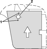
Align the template on the left side of the hood as shown in Figure 1.
-
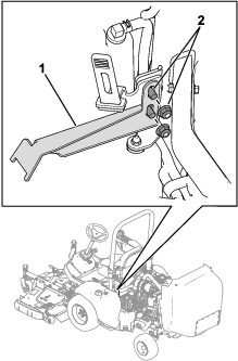
Drill 3 holes into the hood as shown in Figure 2.
-
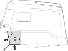
Use the existing hood-strap hardware to secure the latch bracket to the hood strap (Figure 3).
-
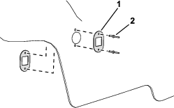
Use 2 rivets (1/2 inch) to secure the latch plates to the hood (Figure 4).
-
Remove the jam nut from the key latch.
-
Insert the key latch into the hood (Figure 5).
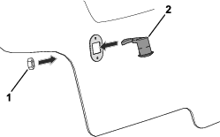
-
Use the previously removed jam nut (Figure 5) to secure the key latch to the hood.
-
Lower the hood and use the key to secure the hood in the lowered position.
Note: Adjust the latch bracket (Figure 3) as necessary so that the hood is secured in the lowered position.
Installing the Decals
Parts needed for this procedure:
| Slope decal (Part No. 144-3952) | 1 |
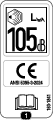
| CE and sound decal (Part No. 144-4015) | 1 |
Apply the decals to a clean and dry surface.
-
Perform the following steps to install the slope decal:
-
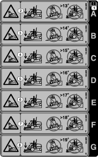
Use the following table to determine which decal is applicable for your traction-unit model and equipped attachments:
Important: If you use more than 1 front attachment, then you must install the lowest applicable slope decal.For example: If you have a Model 31900 traction unit and will use the Model 31970 cutting unit (slope decal A) and the Model 02835 flail (slope decal B), then you must apply slope decal A.
Important: Refer to your traction unit Operator’s Manual for the amount of required rear weight per your traction unit and attachment configuration.
Slope Decal per Traction Unit and Attachment Configuration
Traction Unit Model Number Attachment Model Number or Name Slope Decal Decal to meet required slope standard* Decal for improved slope performance* 31900 31970 A E 31970 and Sunshade A D 31971 A E 31971 and Sunshade A D 31972 A D 31972 and Sunshade B C 31973 A D 31973 and Sunshade B C 31974 A E 31974 and Sunshade A D 31975 A D 31975 and Sunshade B C 02835 B C 02835 and Sunshade A B 31901 31970 B G 31970 and Sunshade B E 31971 B G 31971 and Sunshade B E 31972 B F 31972 and Sunshade A D 31973 B F 31973 and Sunshade A D 31974 B G 31974 and Sunshade B E 31975 B F 31975 and Sunshade B D 02835 B E 02835 and Sunshade A D 31902 31970 B F 31970 and Sunshade B D 31971 B F 31971 and Sunshade B D 31972 A E 31972 and Sunshade A B 31973 A E 31973 and Sunshade A B 31974 B F 31974 and Sunshade B D 31975 A E 31975 and Sunshade A B 02835 A D 02835 and Sunshade A — 31903 31970 A — 31971 A — 31972 A — 31973 A — 31974 A — 31975 A — 02835 A — *When equipped with the appropriate amount of rear weight as shown in your Operator’s Manual. -
Peel the appropriate slope decal from the backing and discard the remaining decals.
-
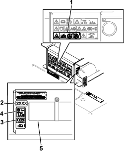
Install the slope decal (Part No. 144-3952) on the existing warning-decal location as shown in Figure 6.
-
-
Install the CE and sound decal (Part No. 144-4015) near the model year decal as shown in Figure 6.
If you have the F60 Flail Mower equipped: You do not need to install the sound decal.
Adjusting the Engine Speed
Parts needed for this procedure:
| Cable guard (Model 31900 and 31901 machines only) | 2 |
| Rivet—1/8 inch (Model 31900 and 31901 machines only) | 2 |
To meet CE noise certification requirements, you must adjust the engine speed for the following machines:
-
Model 31900 and 31901 machines: Refer to Adjusting the Engine Speed and Installing the Cable Guards.
-
Model 31902 and 31903 machines: Refer to Adjusting the Engine Speed.
Adjusting the Engine Speed and Installing the Cable Guards
Note: Use a tachometer to observe the engine speed.
-
Start the engine and allow it to warm up to 71 to 77°C (160 to 170°F).
Note: The display screen shows the engine temperature.
-
Use the throttle control to increase the engine speed to high idle.
-
Observe the current high-idle engine speed on your tachometer.
-
Loosen the throttle-cable jam nuts (Figure 7).
Note: The throttle cable is located on the left side of the engine.
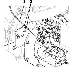
-
Adjust the throttle cable in the bracket (Figure 7) to attain a speed of 3,100 rpm.
-
Tighten the throttle-cable jam nuts.
-
Shut off the engine and remove the key.
-
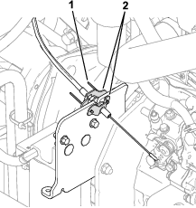
Use 2 rivets (1/8 inch) to install the cable guards around the throttle-cable jam nuts (Figure 8).
If there are no existing holes to install the rivets, use the cable-guard holes to drill 0.4 cm (1/8 inch) holes into the cable-mounting plate.
Adjusting the Engine Speed
Refer to the Toro DIAG User Software Guide for instructions to set the machine to CE Mode.
Note: CE Mode limits the high-idle engine speed to 2,900 rpm while the PTO is engaged.