Note: Determine the left and right sides of the machine from the normal operating position.
Safety
Safety and Instructional Decals
Note: Safety decals and instructions are easily visible to the operator and are located near any area of potential danger. Replace any decal that is damaged or missing.
Installation
Preparing the Machine
-
Move the machine to level ground and engage the parking brake.
-
Lower the cutting units to the ground.
-
Shut off the engine, wait for all moving parts to stop, and remove the key.
-
Unlatch and raise the engine hood, and secure it in the raised position with the prop rod.
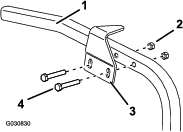
Installing the Hood-Lock Assembly
Parts needed for this procedure:
| Latch support | 1 |
| Latch bracket | 1 |
| Lock assembly | 1 |
| Bolt (5/16 x 3/4 inch) | 1 |
| Bolt (5/16 x 2 inches) | 2 |
| Locknut (5/16 inch) | 3 |
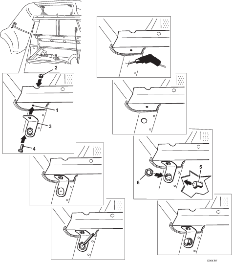
-
Locate the upper (rear) metal frame support running across the underside of the hood.
-
In the upper, left corner of the metal frame, locate the hole drilled in the face of the support.
-
Open the hole using a 5/16 inch drill bit.
-
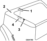
Install the latch support using a bolt (5/16 x 3/4 inch) and locknut (5/16 inch) as shown in Figure 1.
-
Mark the hood at the center hole on the punch-out of the latch support.
-
Remove the latch support.
-
Drill a pilot hole in the plastic hood at the marked spot and then expand the hole to a diameter of 2.54 cm (1 inch).
-
Remove the punch-out from the latch support.
-
Install the latch support to the frame using the bolt (5/16 x 3/4 inch) and locknut (5/16 inch) as shown in Figure 1.
-
Remove the locking nut from the lock assembly.
-
Install the lock assembly through the hood and the latch support, with the catch facing the forward (Figure 1).
-
Install the locking nut onto the bottom of the lock assembly to secure it in place (Figure 1).
-
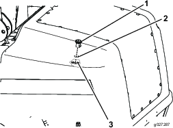
Install the latch bracket to the left frame member, directly below the lock assembly, in the existing holes, as shown in Figure 2.
Note: Center the bolts in the slots of the latch bracket.
-
Secure the latch bracket to the frame member with 2 bolts (5/16 x 2 inches) and 2 locknuts (5/16 inch) as shown in Figure 2.
-
Close the hood slowly to verify that the lock assembly catches on the latch bracket.
Note: If it does not catch, loosen the bolts securing the latch bracket to the frame member and adjust the latch bracket as necessary. Tighten the bolts and verify that the latch catches.
Installing the Hood-Lock Assembly
Parts needed for this procedure:
| Latch support | 1 |
| Latch bracket | 1 |
| Lock assembly | 1 |
| Bolt (1/4 x 1/2 inch) | 1 |
| Bolt (1/4 x 3/4 inch) | 2 |
| Washer (5/16 inch) | 2 |
| Locknut (1/4 inch) | 3 |
-
Locate the upper (rear) metal frame support running across the underside of the hood.
-
In the upper, left corner of the metal frame, locate the hole drilled in the face of the support.
-
Open the hole using a 5/16 inch drill bit.
-
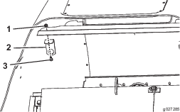
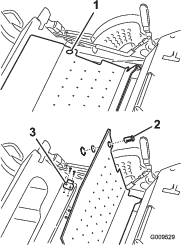
Install the latch support as shown in Figure 3.
-
Mark the hood at the center hole on the punch-out of the latch support.
-
Remove the latch support.
-
Drill a pilot hole in the plastic hood at the marked spot and then expand the hole to 25.4 mm (1 inch).
-
Remove the punch-out from the latch support.
-
Install the latch support to the frame (Figure 3).
-
Remove the locking nut from the lock assembly.
-
Install the lock assembly through the hood and the support latch bracket with the catch facing forward (Figure 4).
-
Install the locking nut onto the bottom of the lock assembly to secure it into place (Figure 4).
-
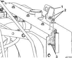
Install the latch bracket on the left side of the frame under the rear of the hood (Figure 5).
Note: The bolts should be approximately centered in the slots of the latch bracket.
-
Close the hood slowly to verify that the latch catches.
Note: If the latch does not catch, loosen the bolts securing the latch bracket to the frame member and adjust the bracket as necessary. Tighten the bolts and verify that the latch catches.
Installing the Floor-Plate-Lock Assembly
Parts needed for this procedure:
| Lock assembly | 1 |
| Floor-plate latch | 1 |
| Carriage bolt (1/4 x 3/4 inch) | 2 |
| Locknut (1/4 inch) | 2 |
-
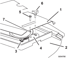
Raise the floor plate (Figure 6).
-
Install the floor-plate latch to the frame (Figure 6) using 2 carriage bolts (1/4 x 3/4 inch) and 2 locknuts (1/4 inch).
-
Remove the 2 locking nuts from the lock assembly.
-
Insert the lock assembly into the hole in the floor plate with the catch facing to the left.
-
Install the locking nuts onto the bottom of the lock assembly to secure it in place.
Note: The mounting holes in the latch are slotted so that you can adjust the lock assembly.
Installing the Hood Handle
Parts needed for this procedure:
| Hood handle | 1 |
| Bolt (1/4 x 1-1/8 inches) | 2 |
| Washer (5/16 inch) | 2 |
| Clamp | 1 |
-
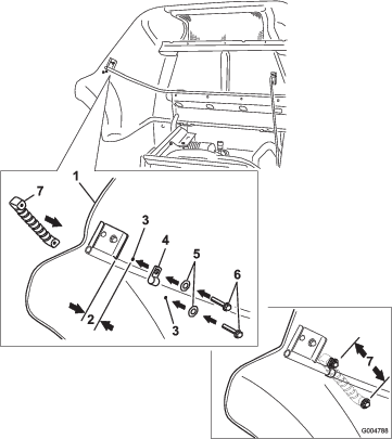
Locate the hood support rail on the inside of the left side of the hood.
-
Measure along the rail, from the support edge, 3.8 cm (1-1/2 inches) as shown in Figure 7.
-
Install the clamp around the rail at this location.
-
Using the clamp as a template, mark and drill an 8 mm (5/16 inch) diameter hole.
-
Install a washer (5/16 inch) and bolt (1/4 x 1-1/8 inches) through the clamp and drilled hole in the hood and into the hood handle.
-
With the hood handle in the approximate position shown in Figure 7, mark the second hole to drill.
Note: The second hole is 12.2 cm (4-13/16 inches) from the first hole.
-
Swing the hood handle out of position and drill a 5/16 inch diameter hole at the marked location.
-
Install a washer onto the other bolt (1/4 x 1-1/8 inches) and through the hood.
-
Secure the handle to the hood using the other washer (5/16 inch) and bolt (1/4 x 1-1/8 inches) as shown in Figure 7.
Note: Tighten the bolts.
Securing the Belt Covers
Parts needed for this procedure:
| Bolt (5/16 x 1-1/4 inches) | 2 |
| Retaining nut (5/16 inch) | 2 |
| Push nut | 2 |
Note: Perform this procedure for the right and left side belt covers.
Securing the Seat Plate
Parts needed for this procedure:
| Bolt (5/16 x 1-1/4 inches) | 1 |
-
Install a bolt in the seat plate to the secure it.
-
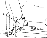
Locate the hole in the front, right side of the seat plate, in front of the manual housing.
-
Install a bolt (5/16 x 1-1/4 inches) in the hole to secure the seat plate (Figure 9).
Installing the Decals
Parts needed for this procedure:
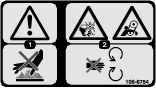
| Safety decal (Part No. 106-6754) | 1 |
| Stability decal (Part No. 138-8202) | 1 |
| Sound decal (Part No. 163-1842) | 1 |
Applying the Safety Decal
-
Thoroughly clean the area of the hood where you are installing the decal (Figure 10).
-
Dampen the area with water or mildly soapy water.
-
Peel off the backing of safety decal, apply it to the hood as shown in Figure 10, and squeegee across the decal using overlapping strokes from the center toward the edges.
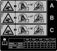
Applying the Tipping Hazard Decal Portion
|
A |
B |
C |
|---|---|---|
|
16 Degrees |
17 Degrees |
18 Degrees |
|
30354 |
30353 |
30457 |
30456 |
31101 |
||
|---|---|---|---|---|---|---|
|
72-inch SDD |
72-inch base |
62-inch base |
60-inch SDD |
100-inch RD |
||
|
30495/TC |
GM7200 1105 Kubota |
C |
C |
C |
B |
— |
|
30487/TC/TE |
GM7210 1105T Kubota |
C |
C |
C |
B |
A |
|
30695 |
GM7210 T4 |
A |
A |
A |
A |
A |
|
30360TE |
GM7200 72-inch SDD - CE deck |
C |
C |
C |
B | |
|
30363TE |
GM7210 72-inch SDD - CE deck |
C |
C |
C |
B | |
|
30461 |
GM7200 <25hp 72-inch base deck |
C |
C |
C |
B | |
|
30464 |
GM7210 T4i 72-inch base |
C |
C |
C |
B | |
|
30467 |
GM7200 <25hp 60-inch SDD |
C |
C |
C |
B | |
|
30468 |
GM7210 T4i 60-inch SDD |
C |
C |
C |
B | |
|
30462 |
GM7200 <25hp 62-inch base |
C |
C |
C |
B | |
|
30465 |
GM7210 62-inch base |
C |
C |
C |
B | |
|
Shaded values show the standard configuration of the model. |
||||||
-
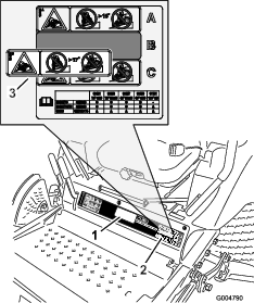
Use the Angle Decal Portion Table and the 2 model-number configuration tables to select the tipping hazard portion of the stability decal (138-8202) for your machine.
-
Thoroughly clean the existing decal where you will install the stability decal (Figure 11).
-
Dampen the area with water or mildly soapy water.
-
Peel off the backing of the decal portion, apply it over the existing tipping-hazard warning as shown in Figure 11, and squeegee across the decal using overlapping strokes from the center toward the edges.
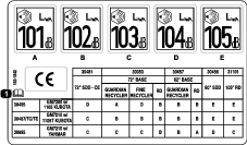
Applying the Sound Power and CE Decal Portions
|
A |
B |
C |
D |
E |
|---|---|---|---|---|
|
101 dBA |
102 dBA |
103 dBA |
104 dBA |
105 dBA |
|
30354 |
30353 |
30457 |
30456 |
31101 |
|||||
|---|---|---|---|---|---|---|---|---|---|
|
72-inch SDD - CE |
72-inch Base |
62-inch Base |
60-inch SDD |
100-inch RD |
|||||
|
Guardian Recycler |
Fine Recycler |
RD |
Guardian Recycler |
RD |
|||||
|
30495/TC/TE |
GM7200 1105 Kubota |
D |
A |
D |
B |
B |
B |
E |
E |
|
30487/TC/TE |
GM7210 1105T Kubota |
C |
B |
B |
B |
B |
B |
E |
E |
|
30695 |
GM7210 w/ Yanmar |
C |
C |
C |
B |
B |
A |
D |
C |
|
30360TE |
GM7200 72” SDD - CE deck |
D |
A |
D |
B |
B |
B |
E | |
|
30363TE |
GM7210 72” SDD - CE deck |
C |
B |
B |
B |
B |
B |
E | |
|
30461 |
GM7200 <25hp 72-inch base deck |
D |
A |
D |
B |
B |
B |
E | |
|
30464 |
GM7210 T4i 72-inch base |
C |
B |
B |
B |
B |
B |
E | |
|
30467 |
GM7200 <25hp 60-inch SDD |
D |
A |
D |
B |
B |
B |
E | |
|
30468 |
GM7210 T4i 60-inch SDD |
C |
B |
B |
B |
B |
B |
E | |
|
30462 |
GM7200 <25hp 62-inch base |
D |
A |
D |
B |
B |
B |
E | |
|
30465 |
GM7210 62-inch base |
C |
B |
B |
B |
B |
B |
E | |
|
Shaded values show the standard configuration of the model. These numbers include an uncertainty value (k) of 1 dBA. Sound power level was determined according to procedures outlined in ISO 11094. |
|||||||||
-
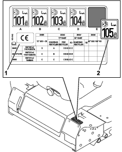
Use the Sound-Power Decal Portion Table and the 2 model-number configuration tables to select the portion of the sound decal (163-1842) for your machine.
-
Thoroughly clean the regulatory decal and the area near the left motion-control lever where you will apply the sound decal and CE decal (Figure 12).
-
Dampen the areas with water or mildly soapy water.
-
Peel off the backing of the decal sound-power portion, apply it to the existing regulatory decal near the left motion-control lever as shown in Figure 12, and squeegee across the decal using overlapping strokes from the center toward the edges.
-
Peel off the backing of the CE portion of sound decal 163-1842 (Figure 12), place it wherever there is space near the regulatory decal, and squeegee across the decal using overlapping strokes from the center toward the edges.