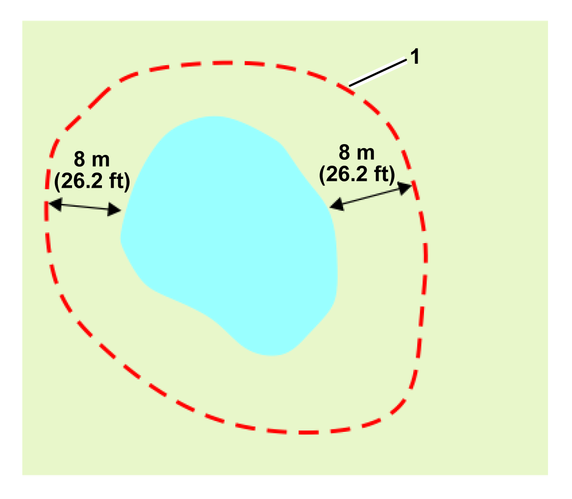
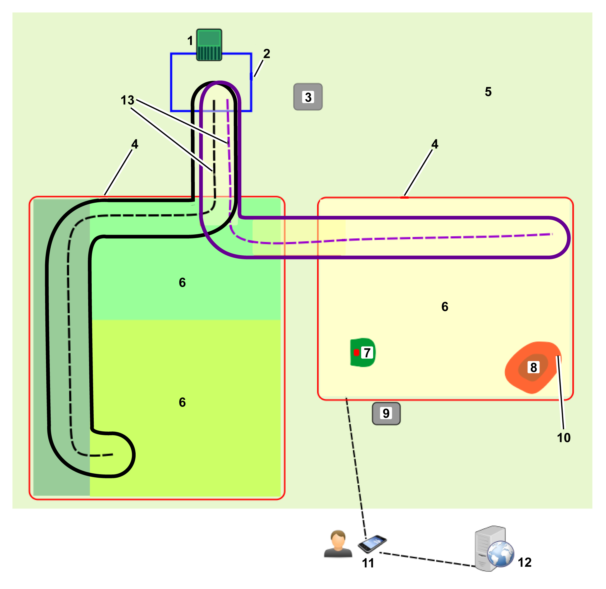
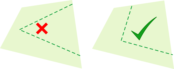
NoGo zones are a means of avoiding
permanent obstacles. In the absence of a peripheral wire, it is important
that you are aware of the conditions relating
to the avoidance of obstacles before you create them. Permanent obstacles
and the means of avoiding them should be set
out on the installation plan.
You also need to take into account
the dimensions described below before defining the NoGo zone.
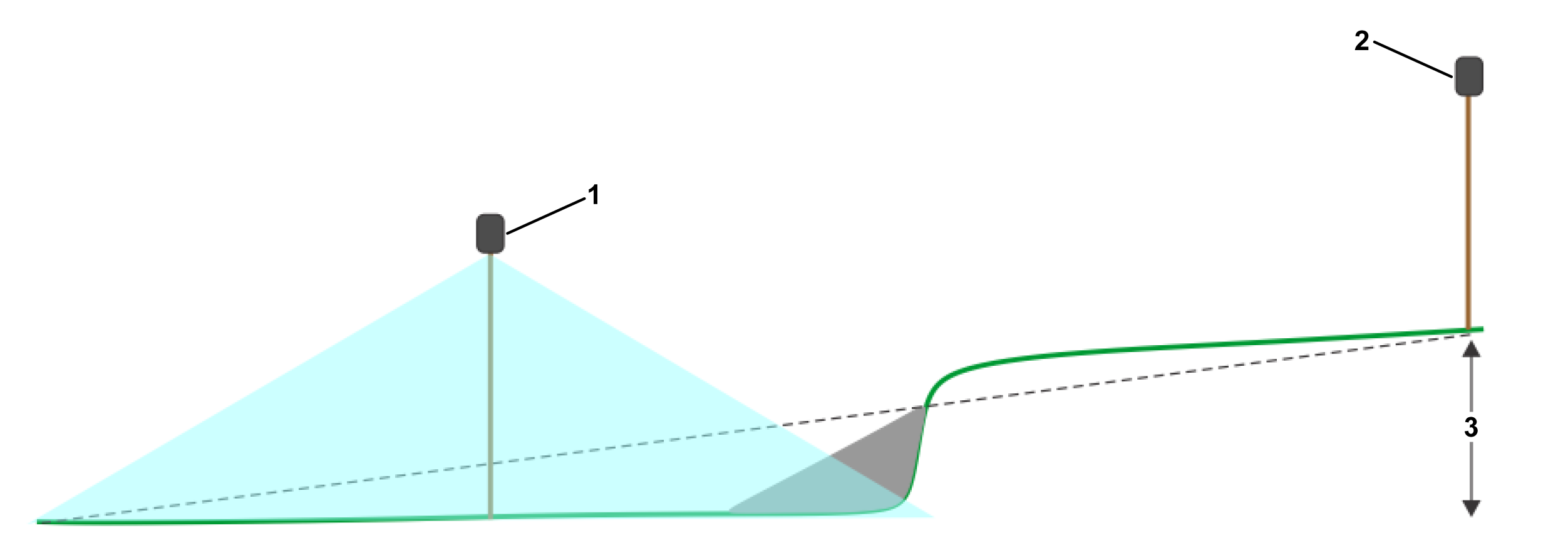
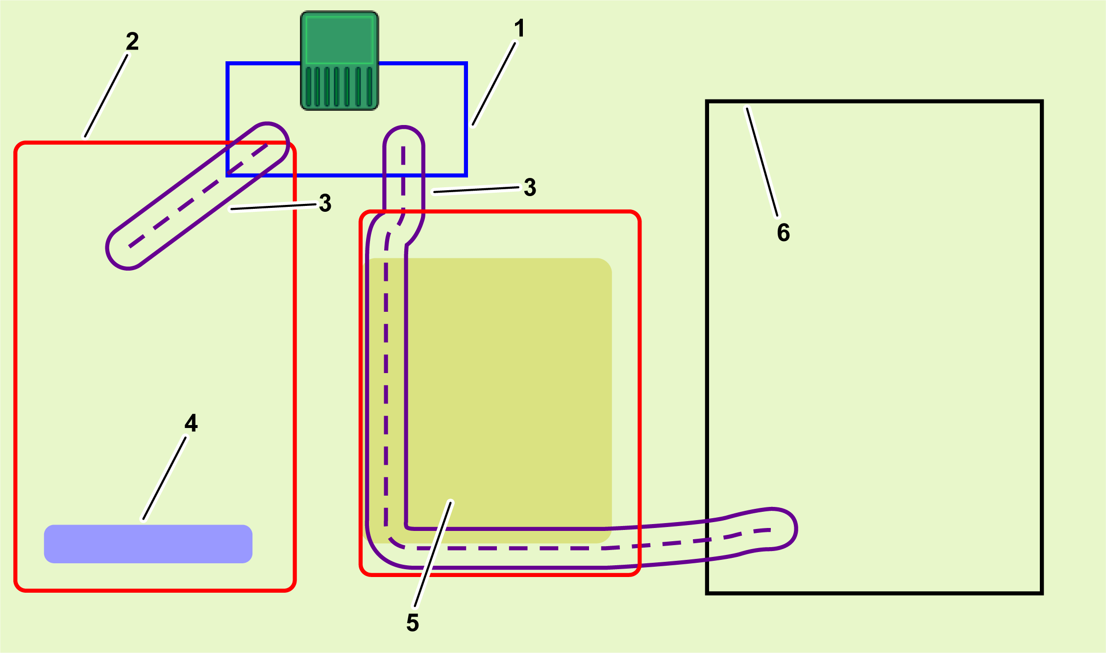
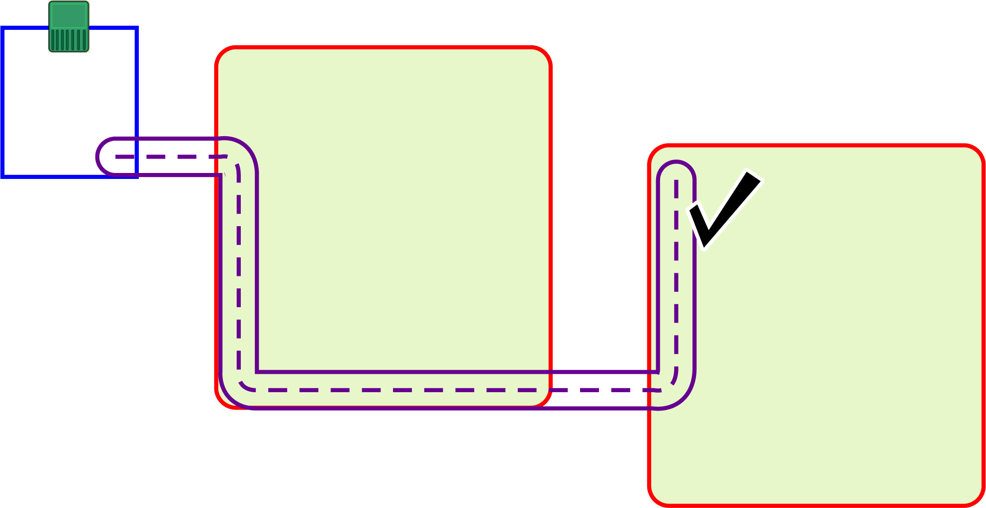
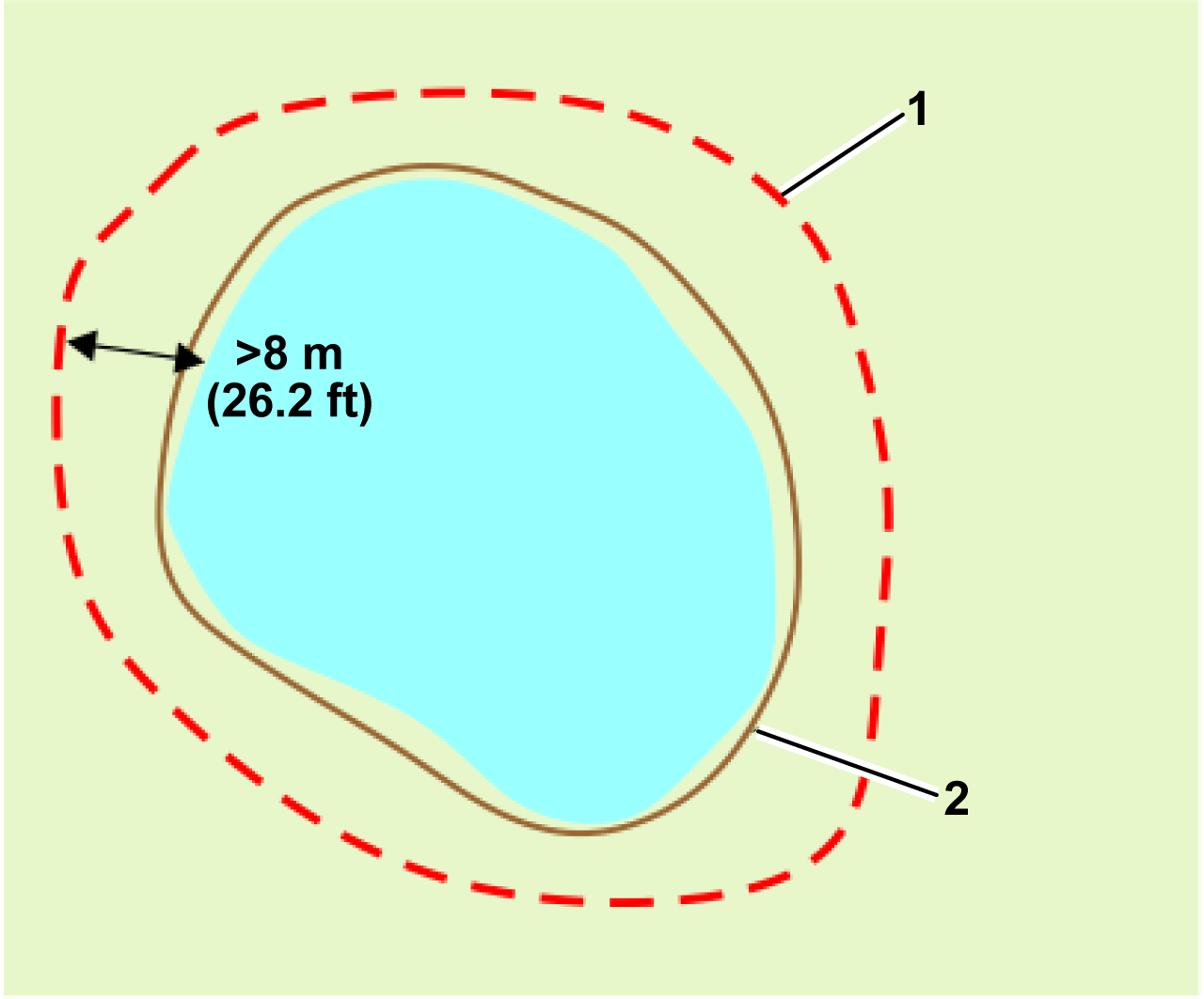
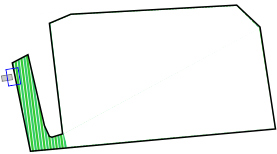
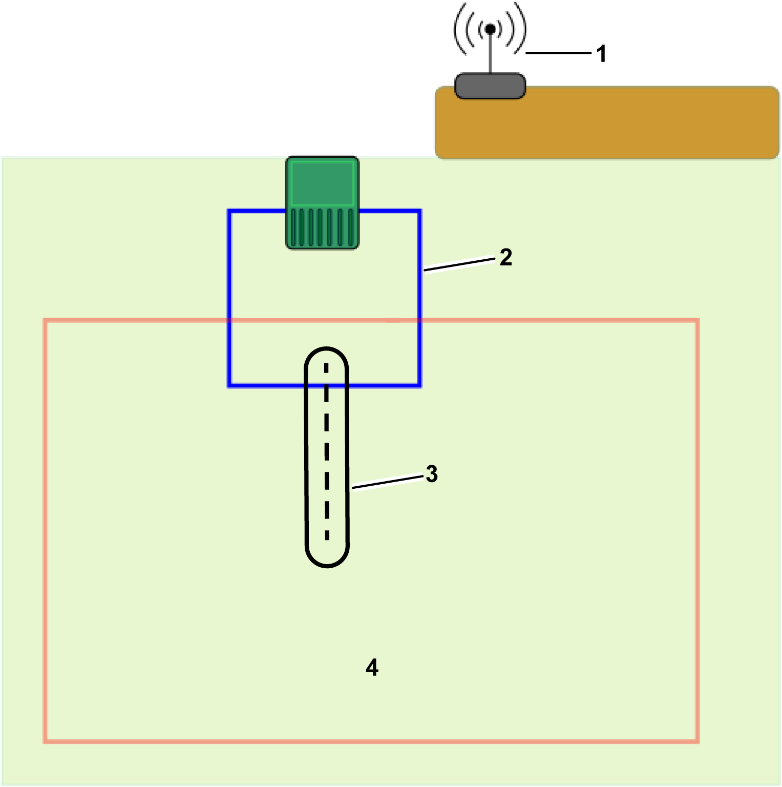
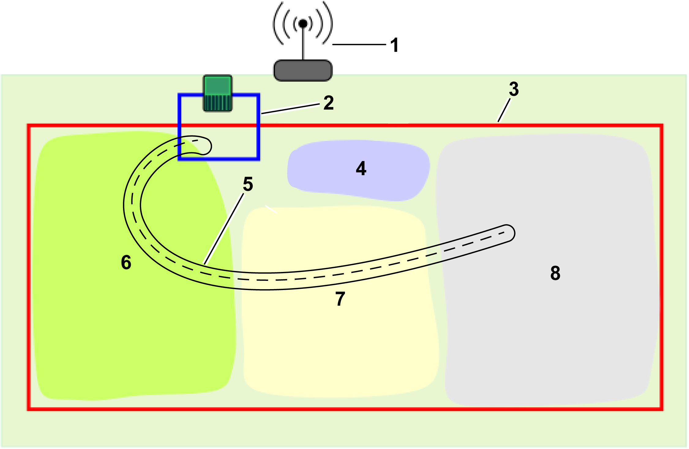
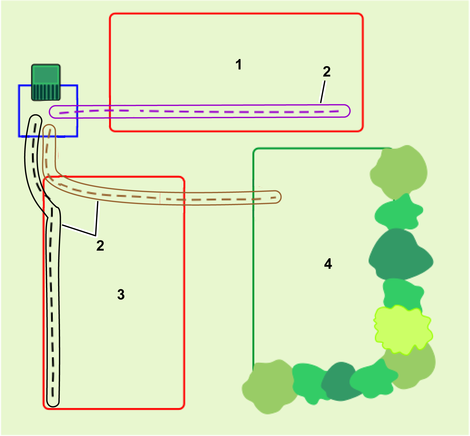
G578641
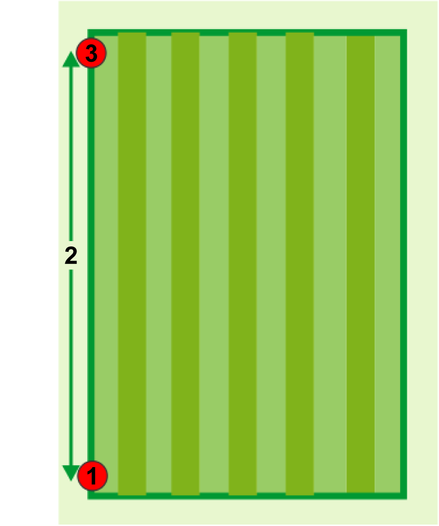
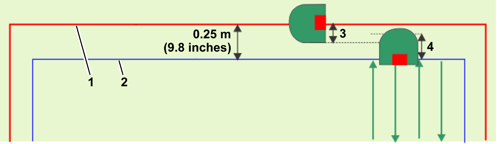
-
Working area boundary
-
Working area
-
Area to be excluded from the working
area
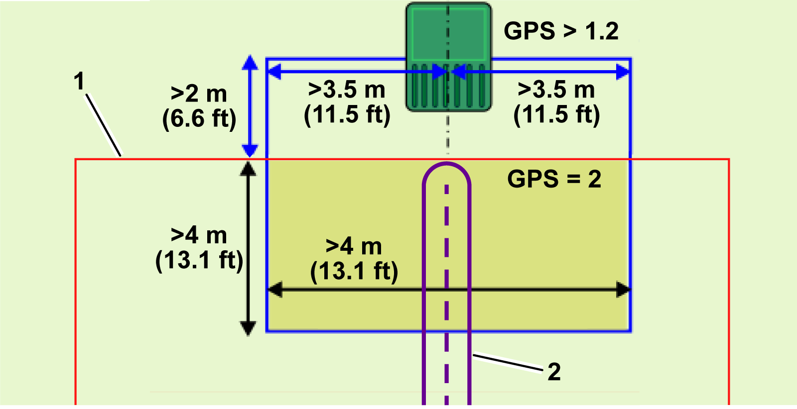
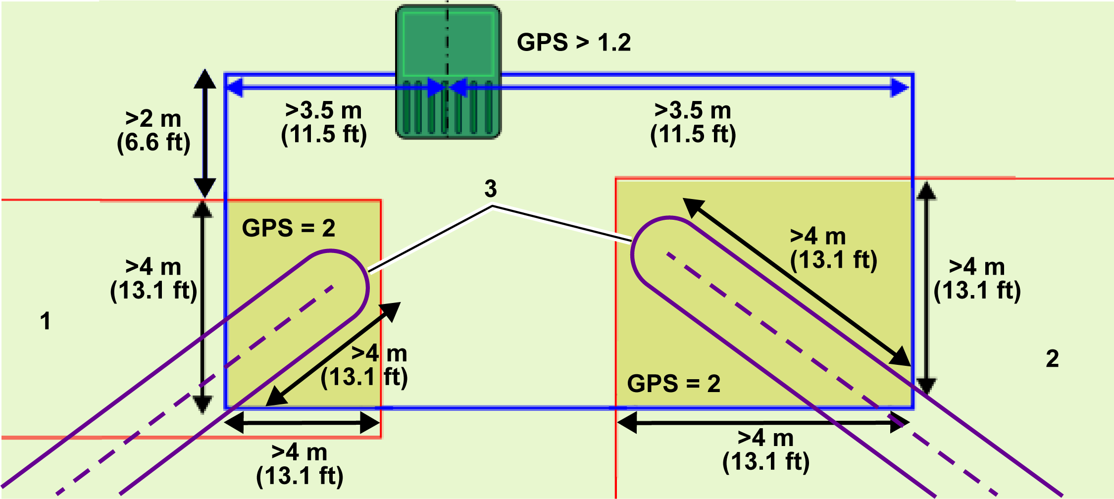
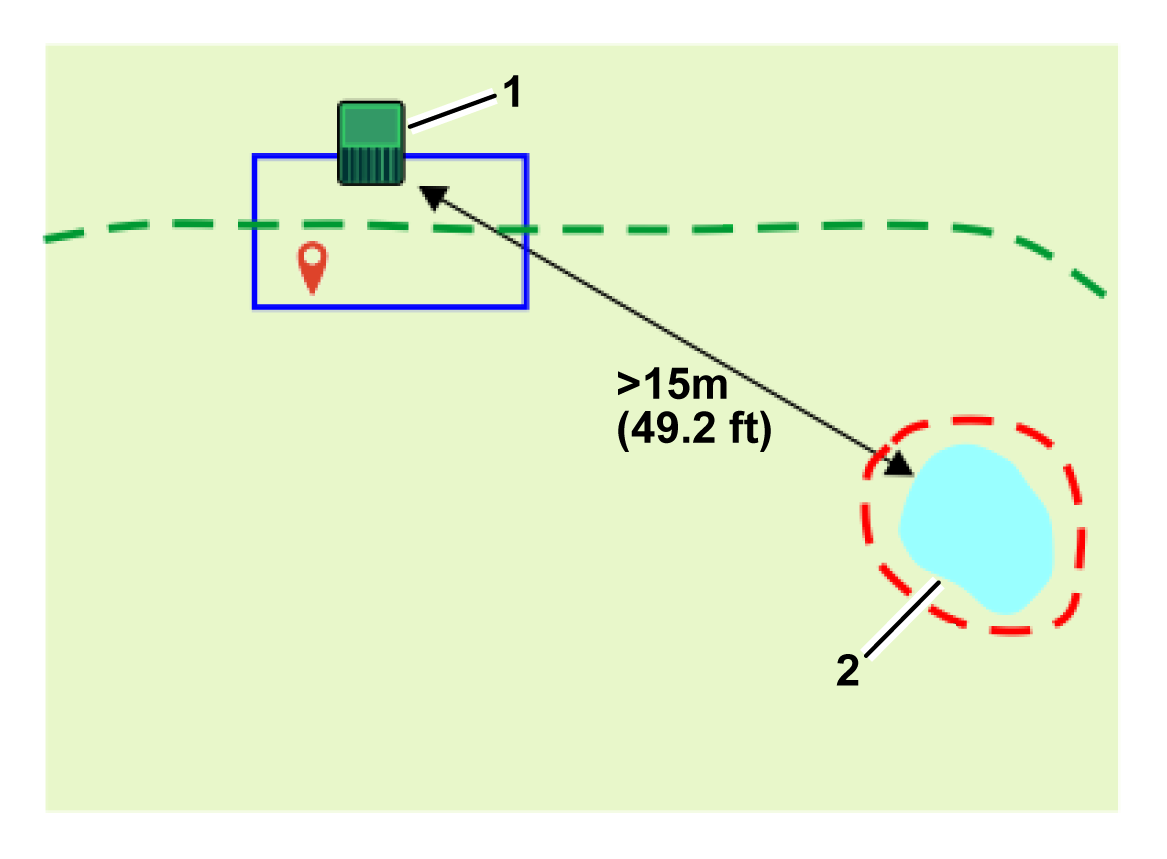
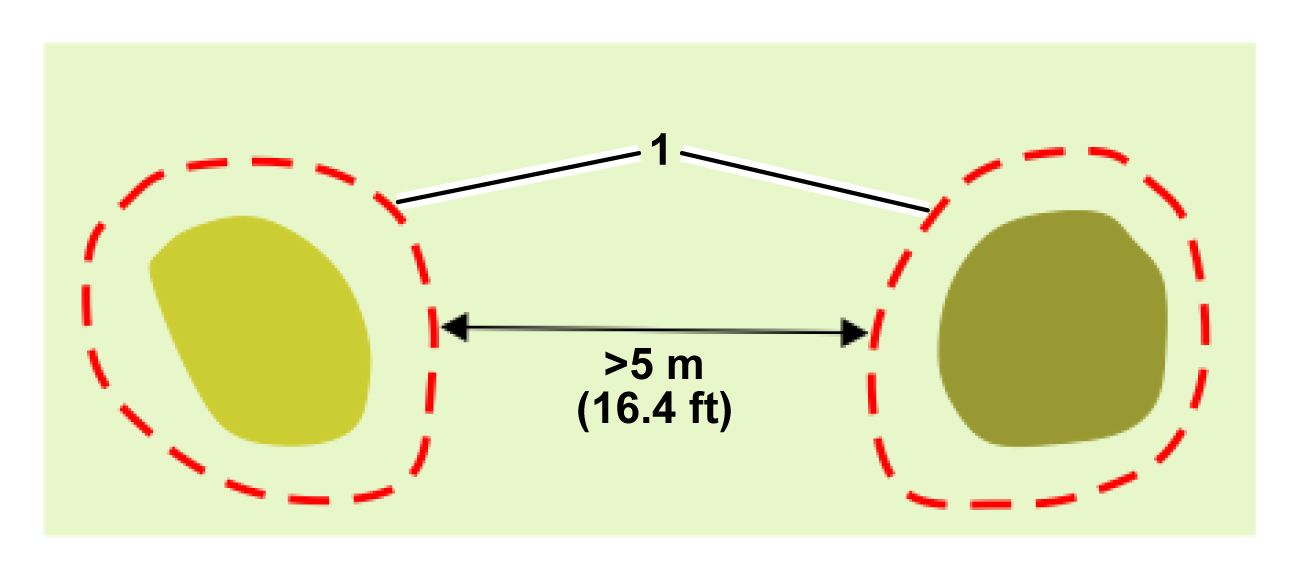
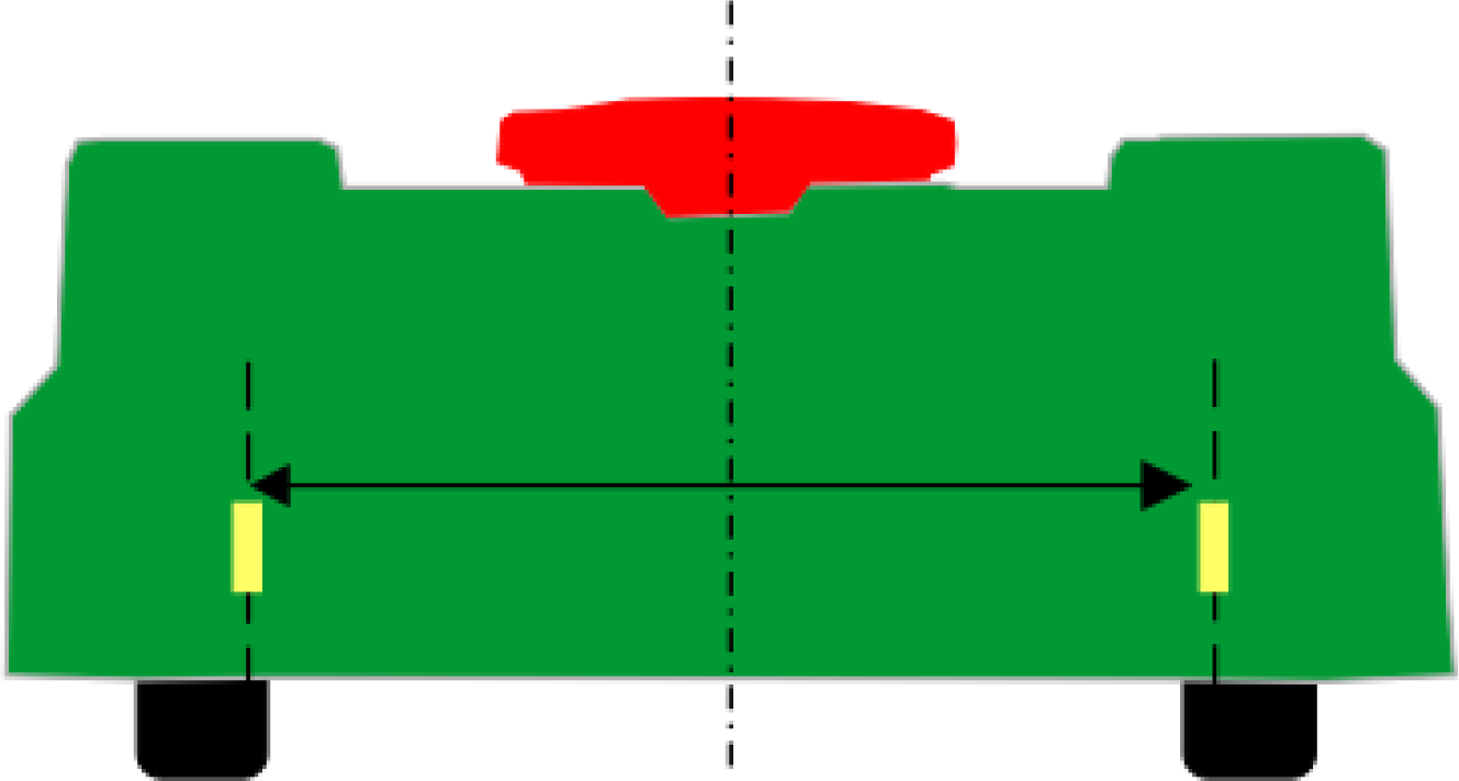
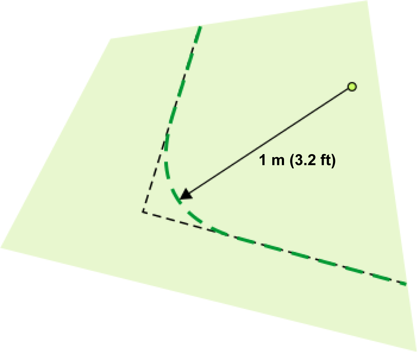
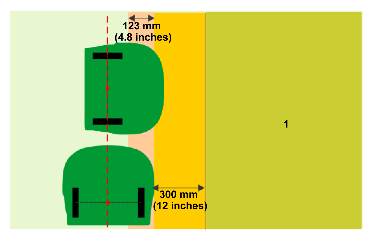
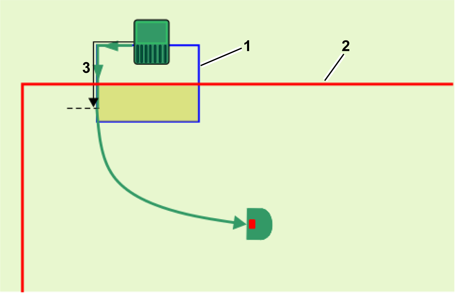
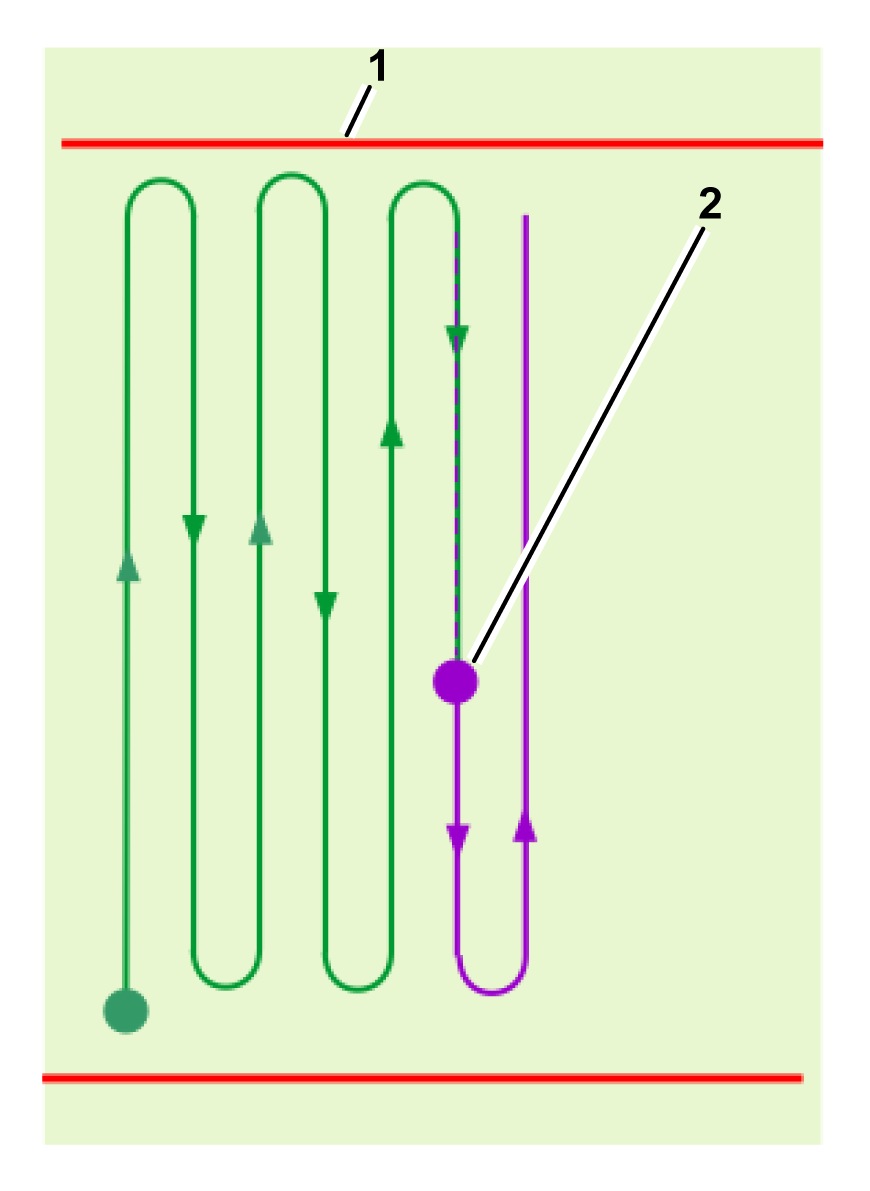
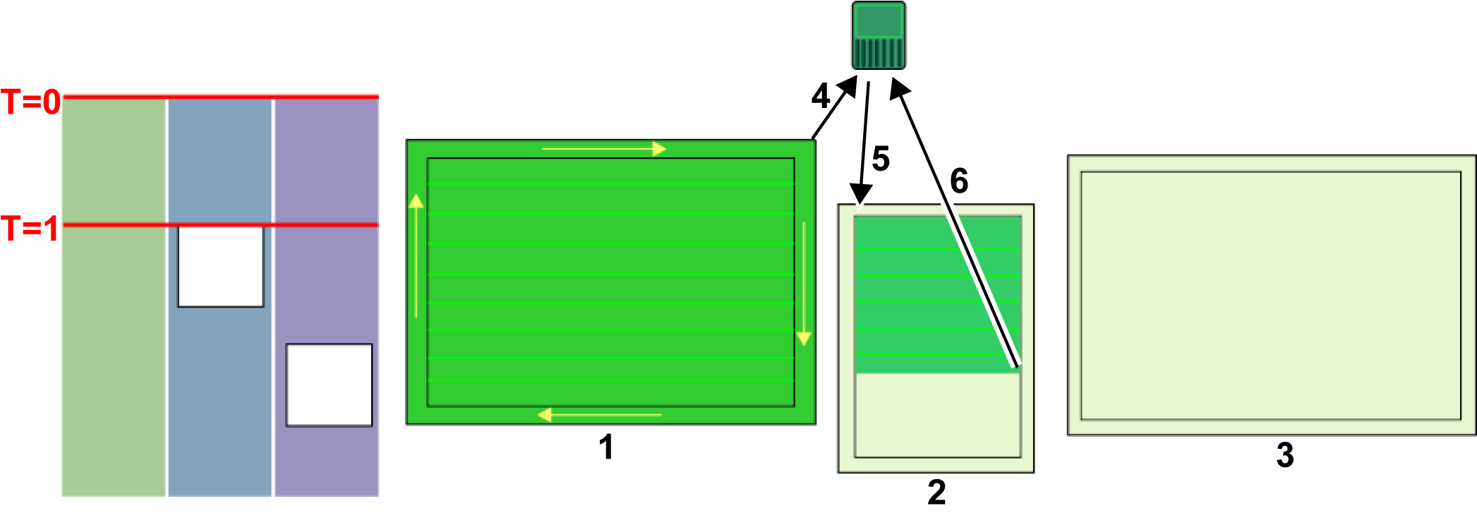
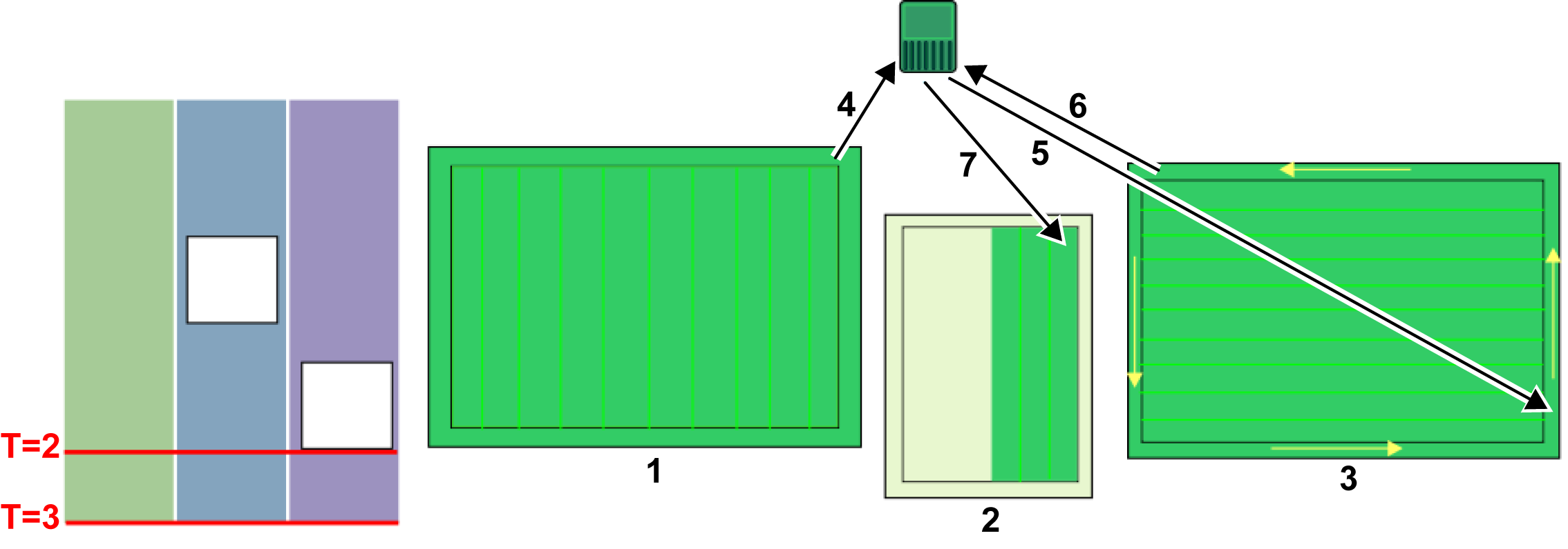
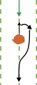
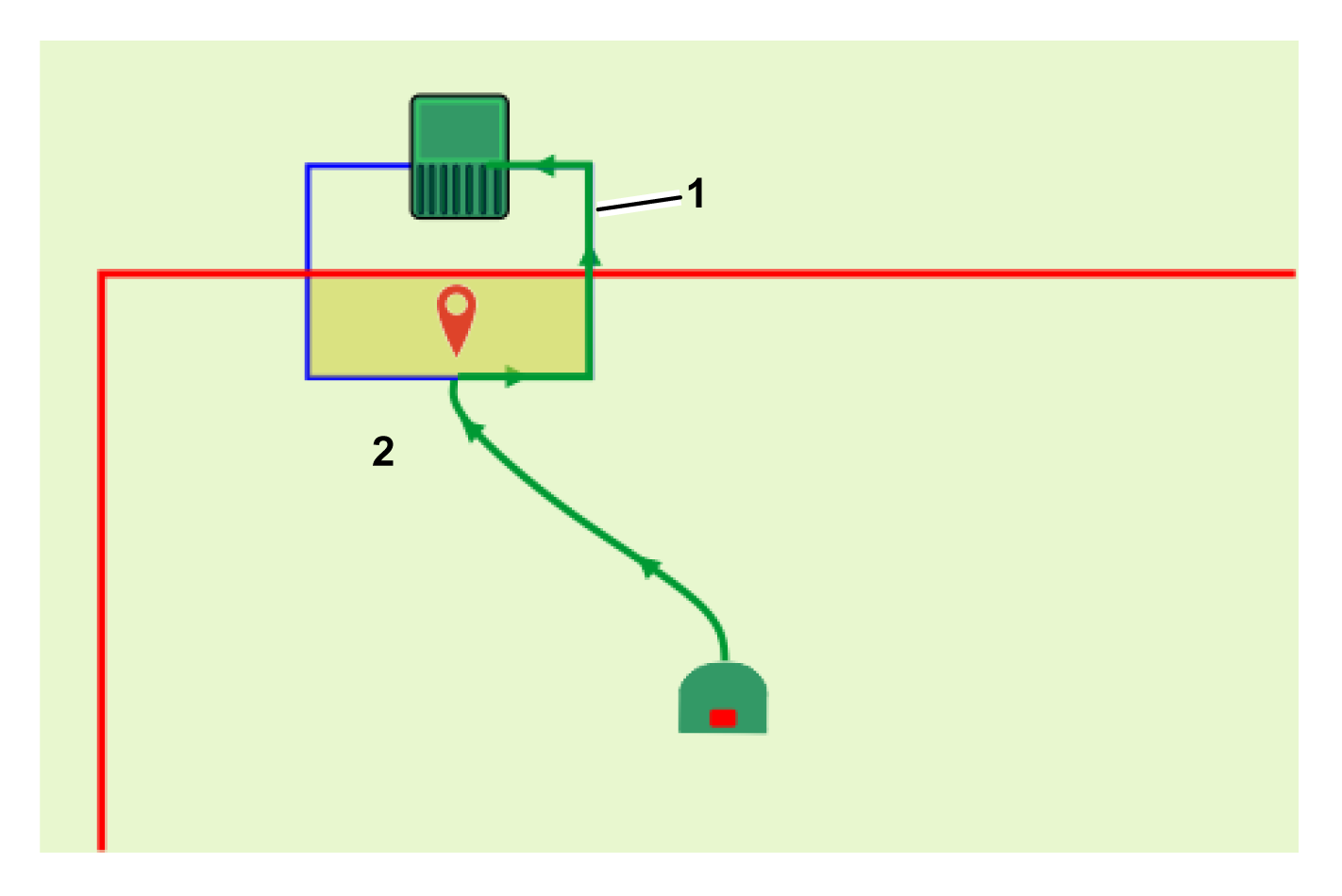
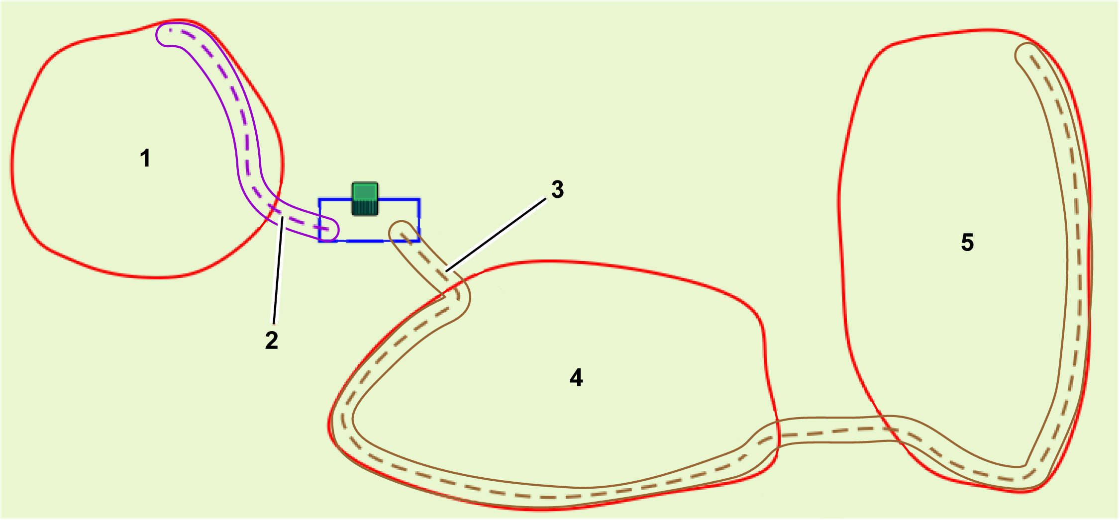
As can be seen from the preceding
figure, when the robot is performing the boundary discovery or working
in a direction parallel to the boundary, the
location of the registered point on the boundary of the NoGo zone
will be away from the actual area being excluded.
This distance is half the width of the robot's body, or 639 mm (25.2
inches).
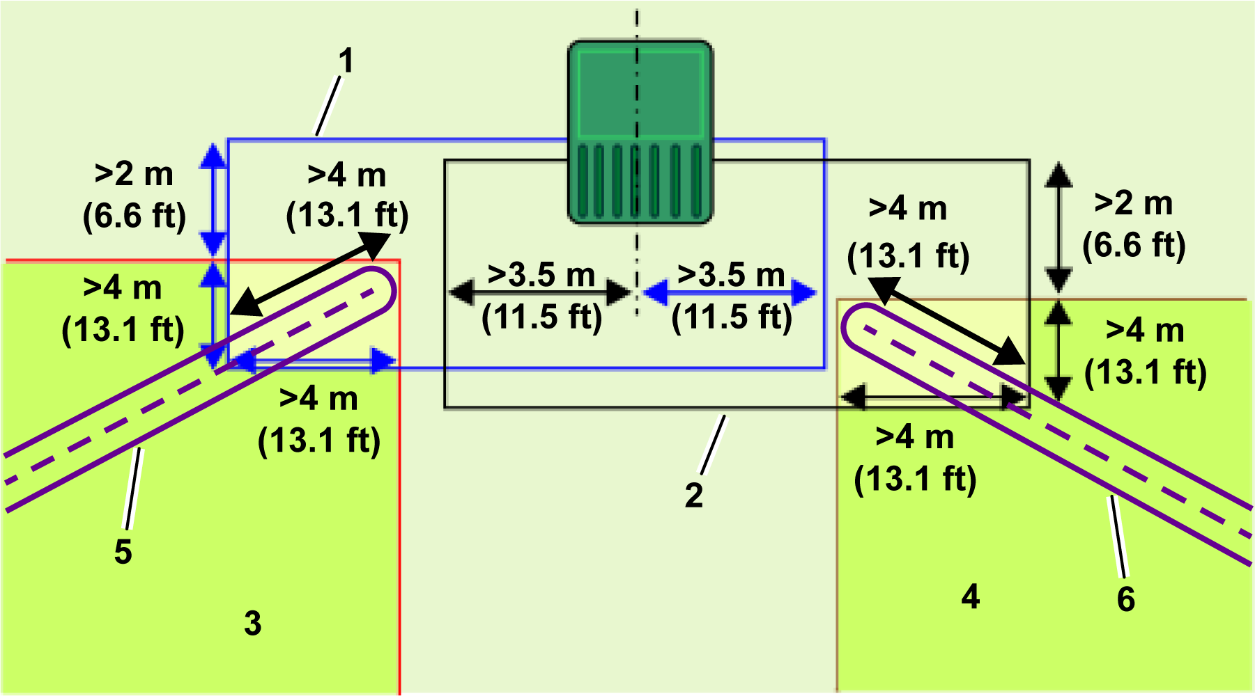
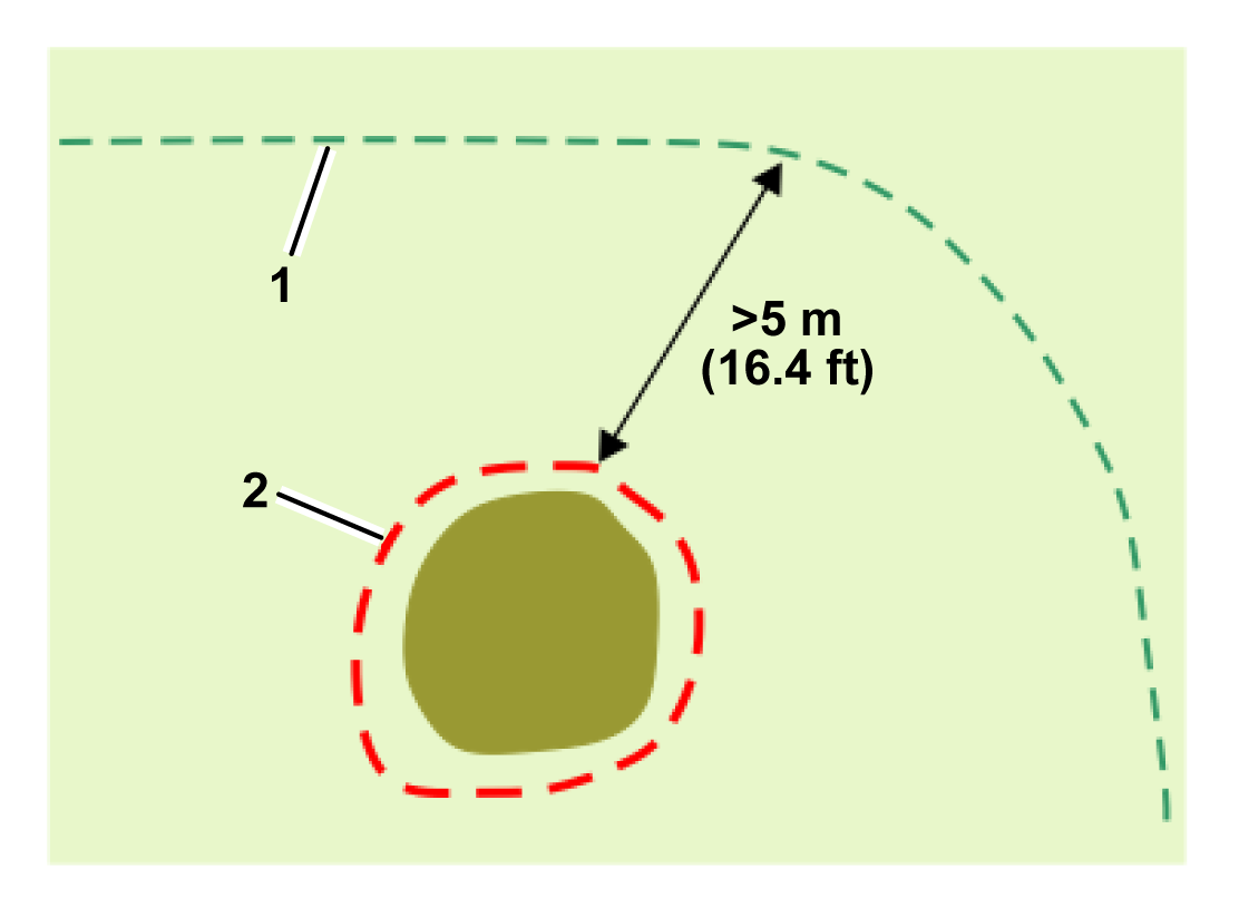
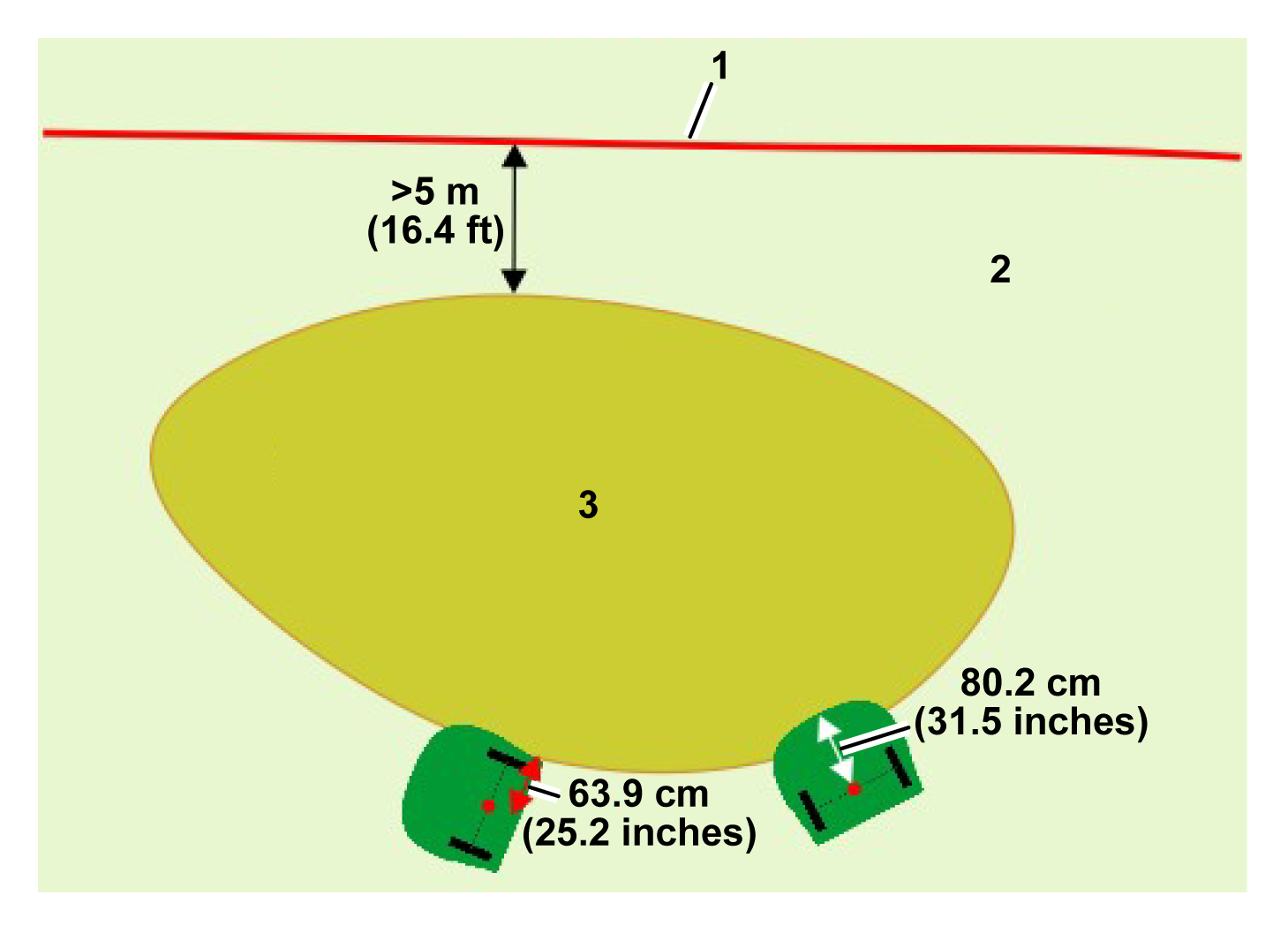
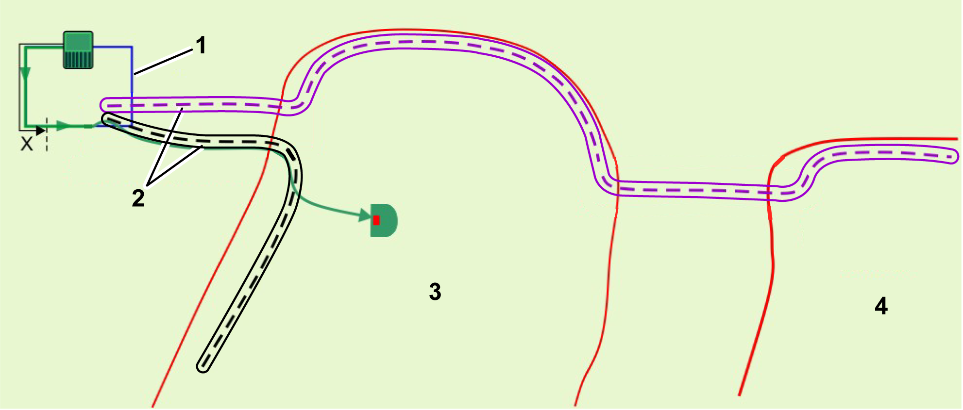
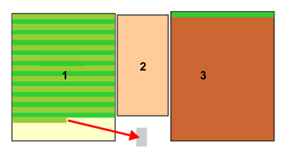
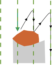
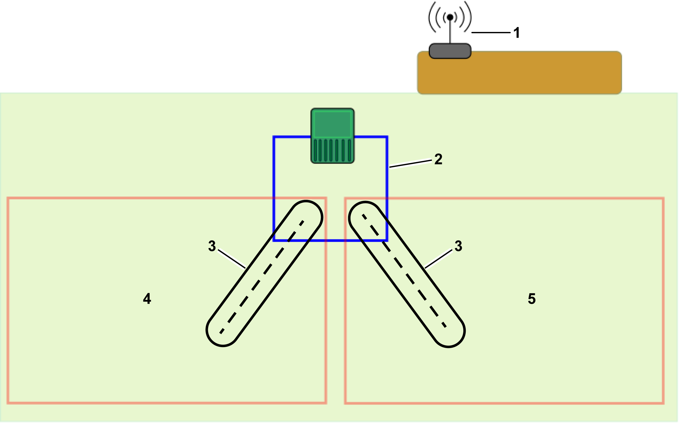
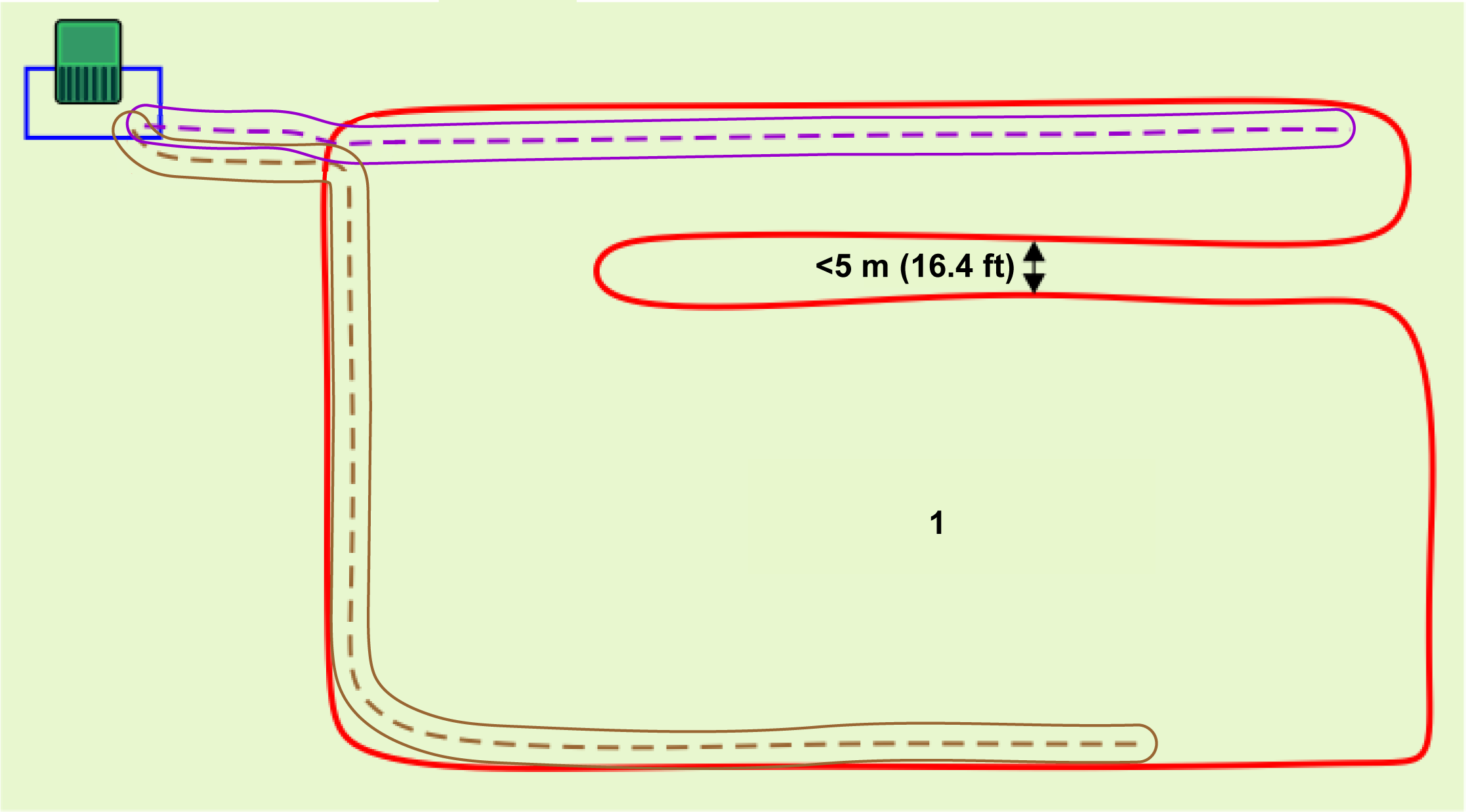
When the pattern direction is
perpendicular to the edge of the area, the robot will stop when the
center of the axle between the rear wheels reaches
the registered position of the boundary of the NoGo zone. In this
case, the registered GPS position of the boundary
of the NoGo zone will be away from the front bumper of the robot.
The distance between the center point of the
rear axle and the front of the body is 802 mm (31.5 inches). When
the pattern direction is perpendicular to the edge of
the area, the nose of the robot will enter further over the
boundary of the NoGo zone compared to the side of the robot when
the pattern is parallel to the edge of the area.
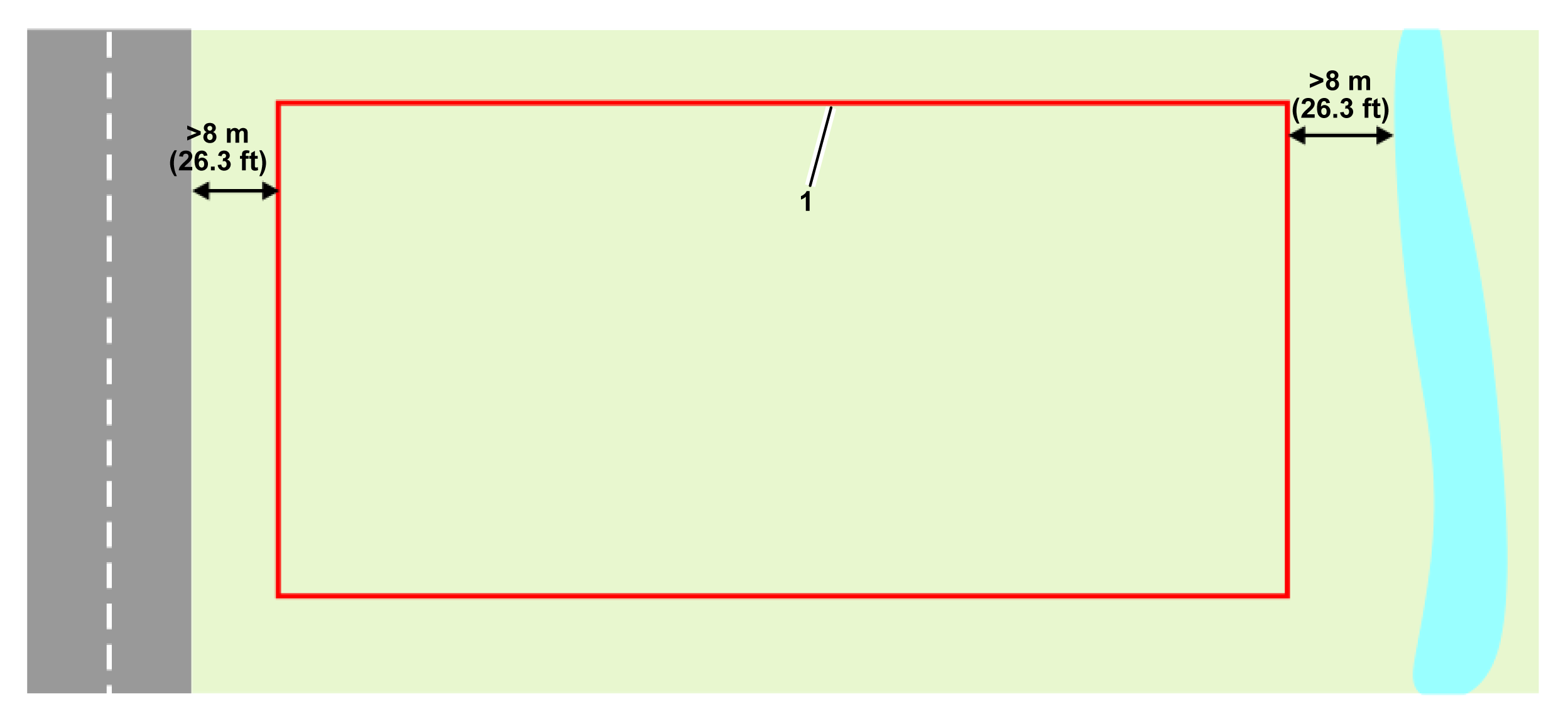
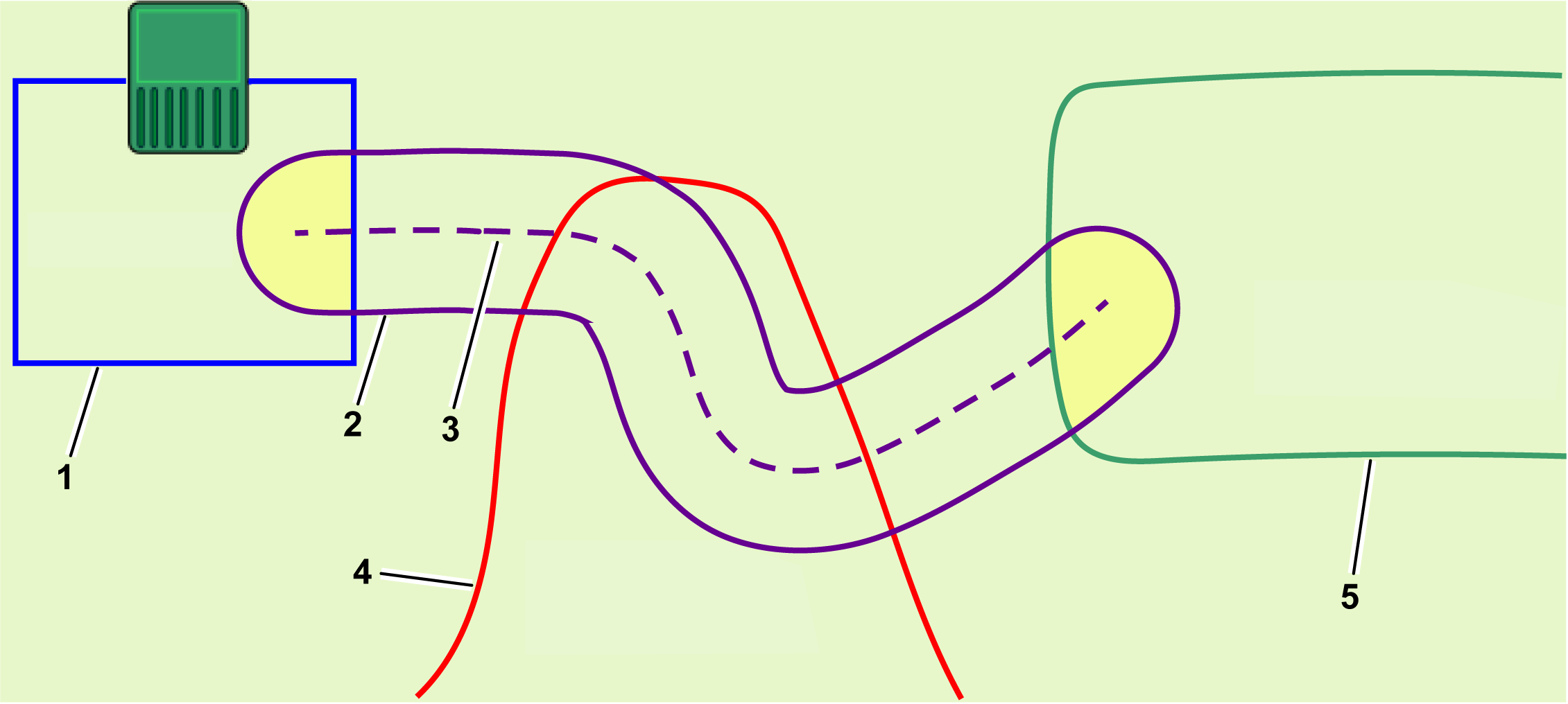
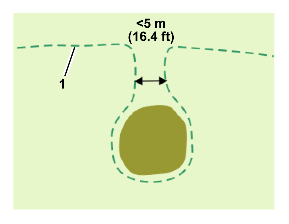
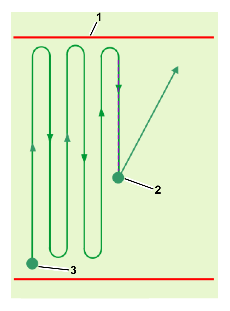
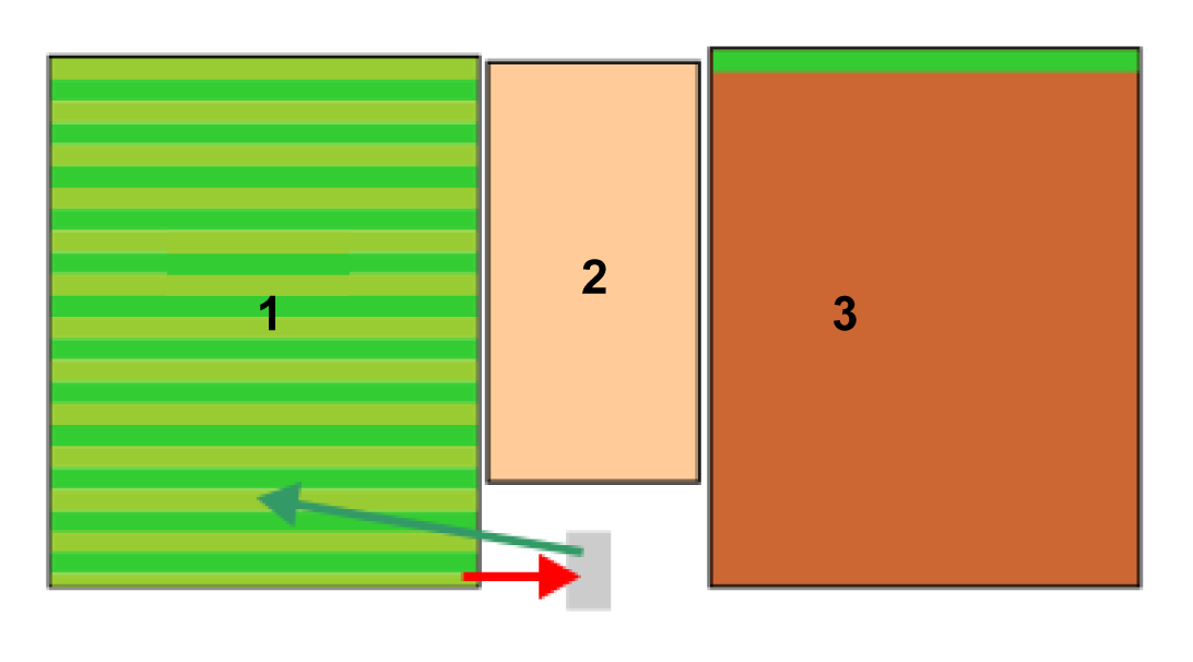
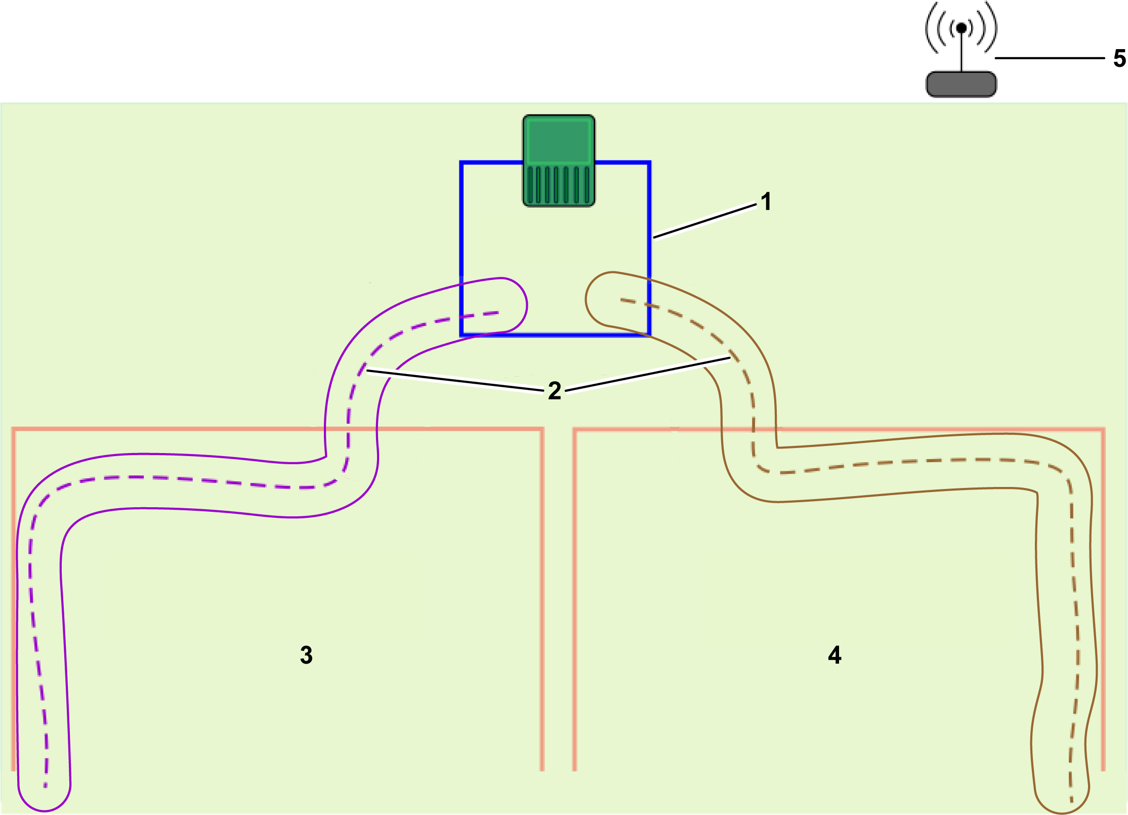
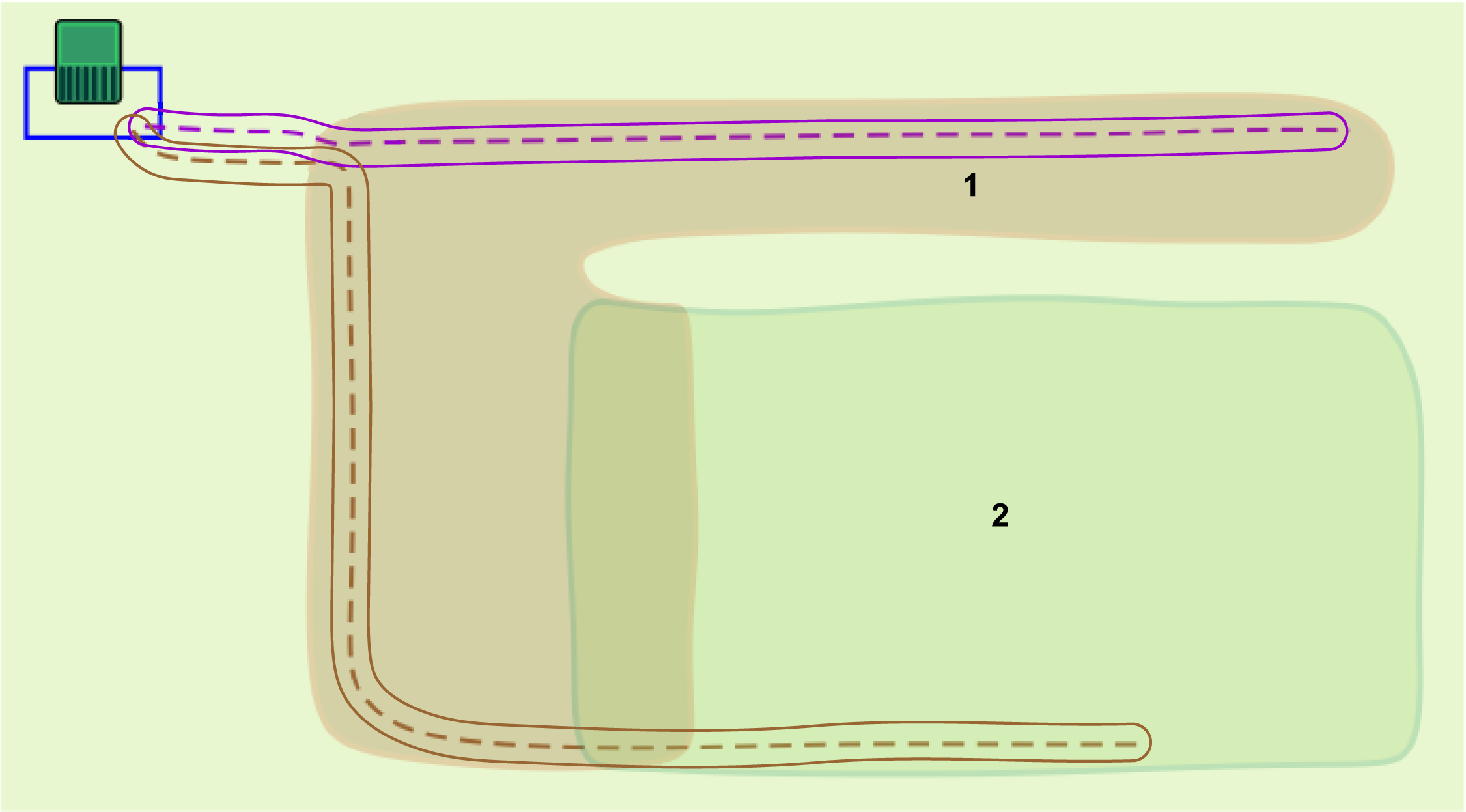
To
avoid the robot entering the area to be excluded or colliding with
an obstacle, a minimum
distance of 300 mm (12 inches) between the excluded area and
the side of the robot should to be respected when registering the
NoGo zone.
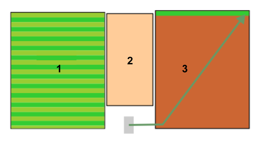
The robot will work up to a distance
away from the defined margin (which should be a minimum of 300 mm
(12 inches) from the side of the robot) when
registering the zone. For the robot, this distance is 123 mm (4.8
inches).
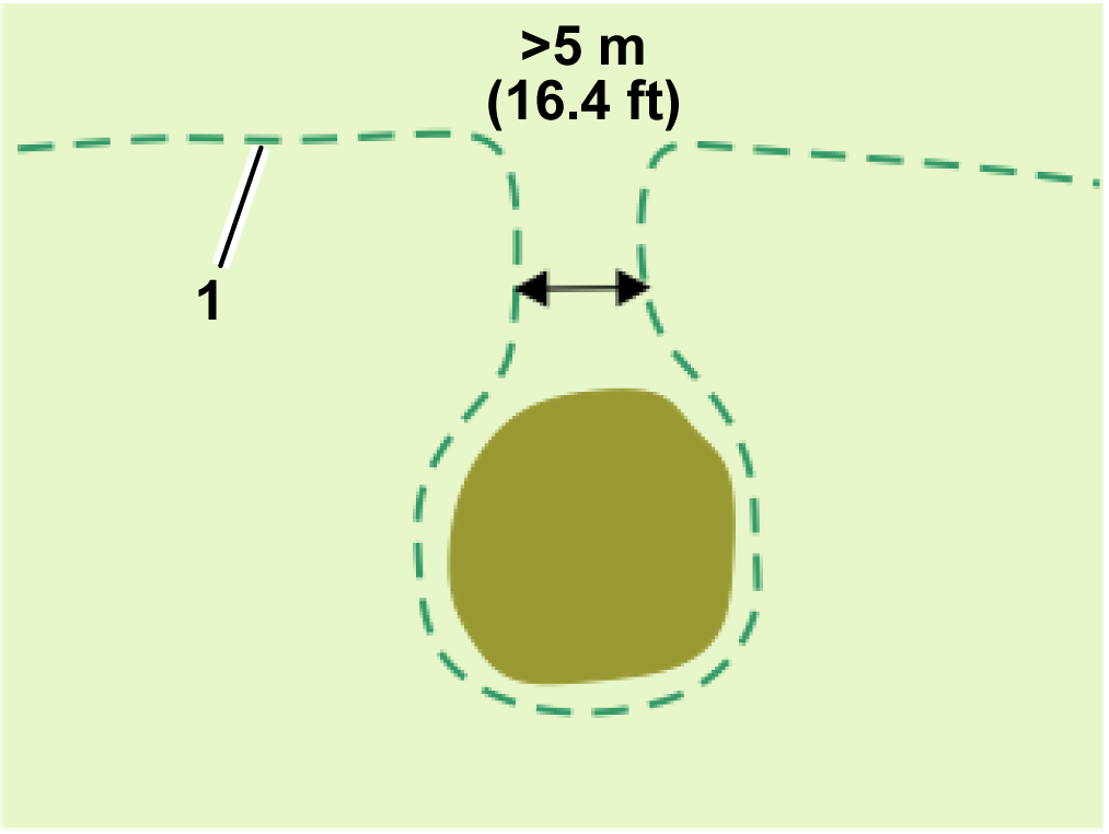
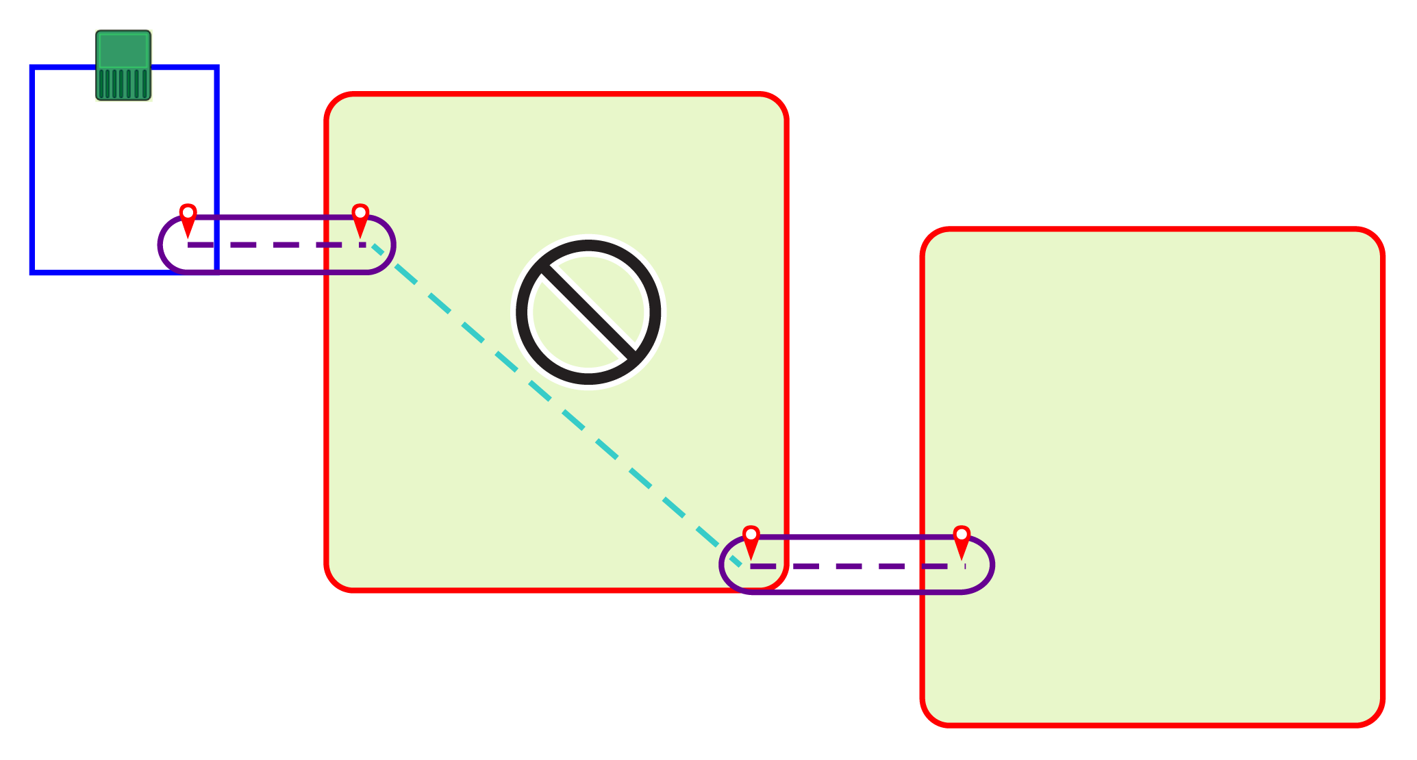
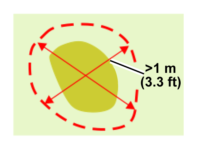
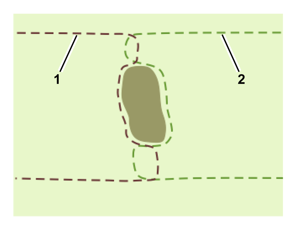
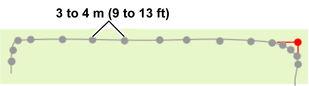
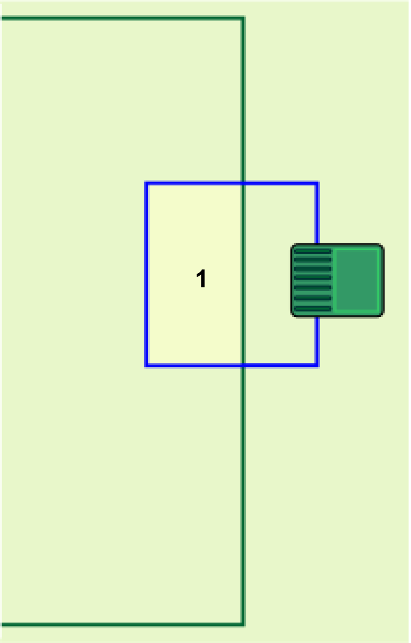
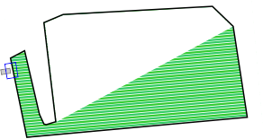
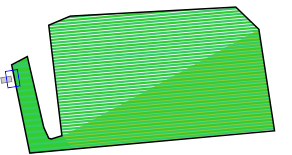
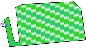
G578642
-
Area to be excluded from the working
area
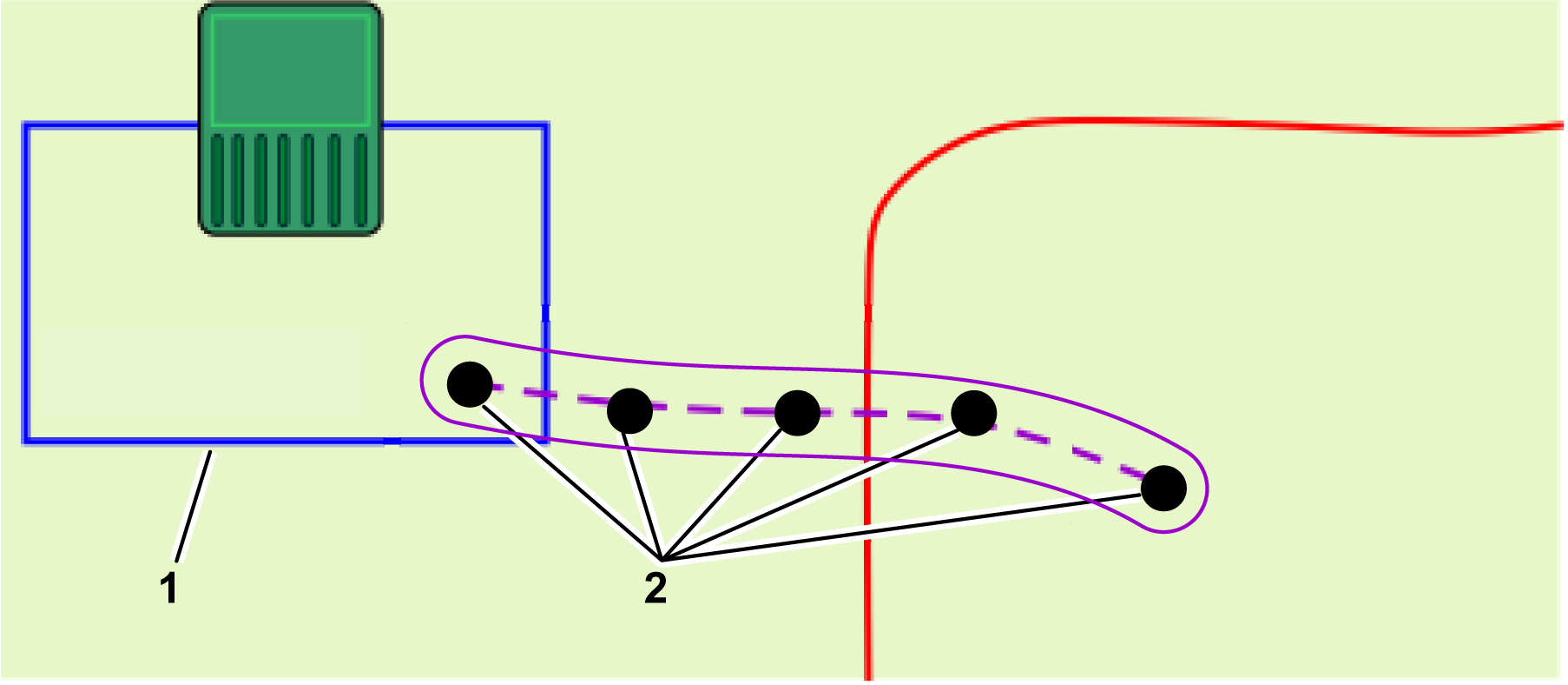
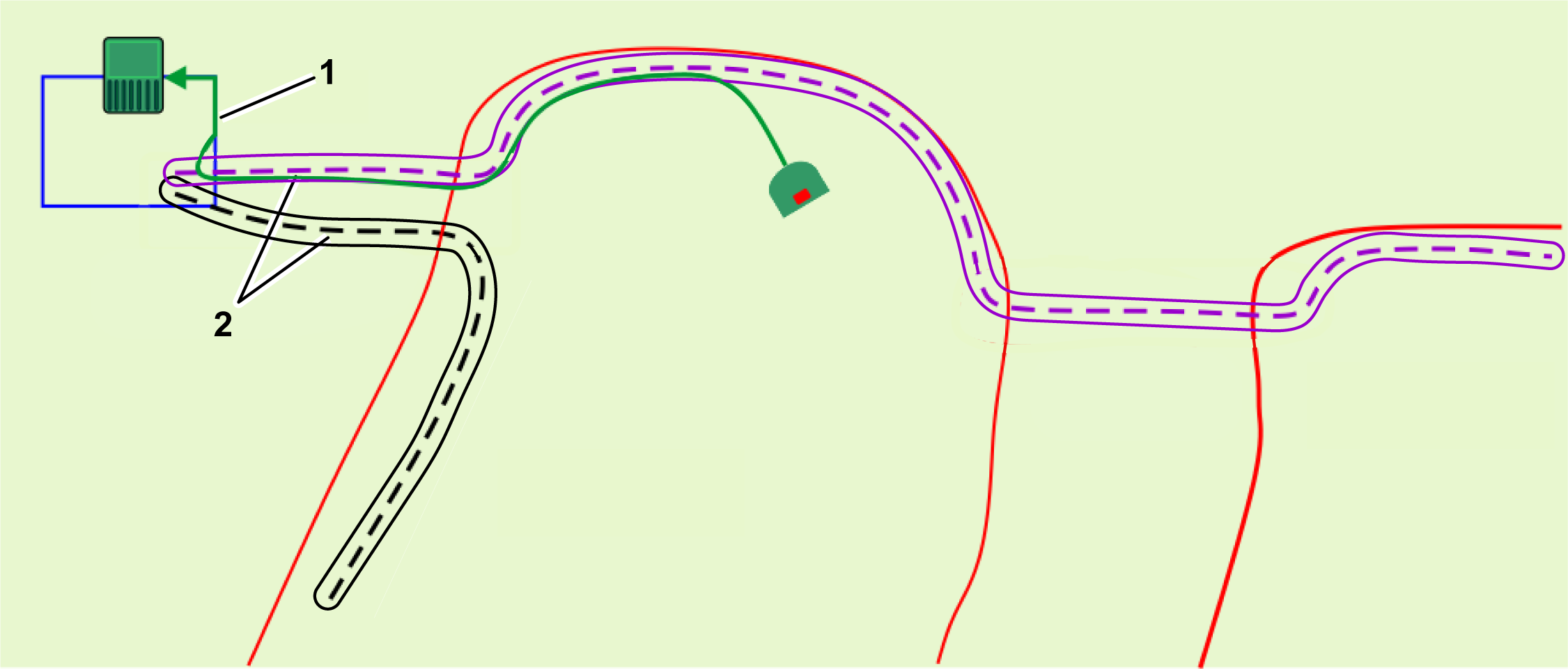
There are 2 methods by which a
NoGo zone can be created: