
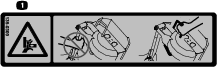
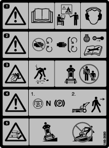
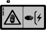
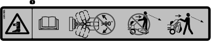
 WARNING


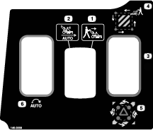


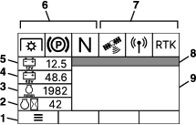


 in the lower right hand corner of the screen.
Maintenance
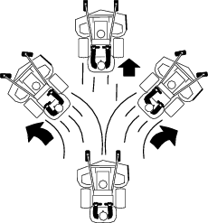
Note: Determine the left and right sides of the machine from the normal operating position.
Maintenance Safety
-
Park the machine on a level surface, disengage the drives, engage the parking brake, shut off the engine, remove the key, and disconnect the spark-plug wire. Wait for all moving parts to stop before leaving the operator’s position. Allow the machine to cool before servicing, adjusting, fueling, cleaning, or storing.
-
If you leave the key in the switch, someone could accidently start the engine and seriously injure you or other bystanders. Remove the key from the switch before you perform any maintenance.
-
Never allow untrained personnel to service machine.
-
Turn the battery-disconnect switch to the OFF position and disconnect the spark-plug wire before making any repairs. Disconnect the negative terminal first and the positive last. Reconnect the positive terminal first and negative last.
-
Keep all guards, shields, switches, and all safety devices in place and in proper working condition. Frequently check for worn or deteriorating components and replace them with genuine Toro parts when necessary.
Warning
Removal or modification of original equipment, parts and/or accessories may alter the warranty, controllability, and safety of the machine. Unauthorized modifications to the original equipment or failure to use original Toro parts could lead to serious injury or death. Unauthorized changes to the machine, engine, fuel, or venting system may violate applicable safety standards, such as ANSI, OSHA, and NFPA, and/or government regulations, such as EPA and CARB.
-
Use care when checking blades. Wrap the blade(s) or wear gloves, and use caution when servicing them. Only replace damaged blades. Never straighten or weld them.
-
Do not rely solely on mechanical or hydraulic jacks for support. Use adequate jack stands.
-
Carefully release pressure from components with stored energy.
-
Keep your hands and feet away from moving parts or hot surfaces. If possible, do not make adjustments with the engine running.
-
Keep all parts in good working condition and all hardware tightened, especially the blade-attachment hardware.
Recommended Maintenance Schedule(s)
| Maintenance Service Interval | Maintenance Procedure |
|---|---|
| After the first 5 hours |
|
| After the first 50 hours |
|
| After the first 100 hours |
|
| Before each use or daily |
|
| Every 40 hours |
|
| Every 50 hours |
|
| Every 100 hours |
|
| Every 160 hours |
|
| Every 250 hours |
|
| Every 500 hours |
|
| Yearly |
|
Important: Refer to your engine owner's manual for additional maintenance procedures.
Caution
If you leave the key in the switch, someone could accidently start the engine and seriously injure you or other bystanders.
Shut off the engine and remove the key from the switch before you perform any maintenance.
Pre-Maintenance Procedures
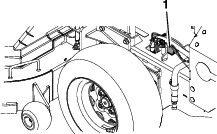
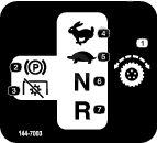
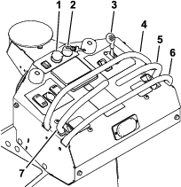
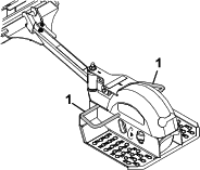
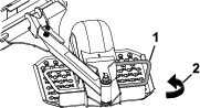
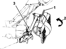
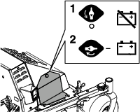
Using the Battery-Disconnect Switch
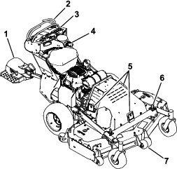
Located on the right side of the machine under the hood access panel.
-
Park the machine on a level surface, disengage the PTO, and move the motion-control levers outward to the PARK position.
-
Shut off the machine, remove the key, and wait for all moving parts to stop before leaving the operating position.
-
Turn the battery-disconnect switch to the ON or OFF position.
Check for Loose Hardware
| Maintenance Service Interval | Maintenance Procedure |
|---|---|
| Before each use or daily |
|
-
Park the machine on a level surface, disengage the PTO, and move the motion control levers outward to the PARK position.
-
Shut off the machine, remove the key, and wait for all moving parts to stop before leaving the operating position.
-
Visually inspect machine for any loose hardware or any other possible problem. Tighten hardware or correct the problem before operating.
Lubrication
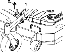
Greasing the Front Caster Pivots
| Maintenance Service Interval | Maintenance Procedure |
|---|---|
| Yearly |
|
Grease type: Lithium or molybdenum grease
-
Remove the dust cap and adjust the caster pivots; refer to Adjusting the Caster-Pivot Bearings.
Note: Keep the dust cap off until you have finished greasing the caster pivots.
-
Remove the hex plug.
-
Thread a grease fitting into the hole.
-
Pump grease into the fitting until it oozes out around the top bearing.
-
Remove the grease fitting from the hole.
-
Install the hex plug and dust cap.
Greasing the Machine
| Maintenance Service Interval | Maintenance Procedure |
|---|---|
| Yearly |
|
Note: See the chart for the service intervals.
-
Park the machine on a level surface, disengage the PTO, and move the motion control levers outward to the PARK position.
-
Shut off the machine, remove the key, and wait for all moving parts to stop before leaving the operating position.
-
Lubricate fittings with one to two pumps of NLGI grade #2 multi-purpose gun grease.
Refer to the following chart for fitting locations and lubrication schedule.
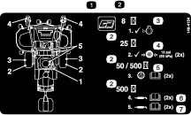
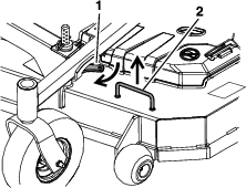
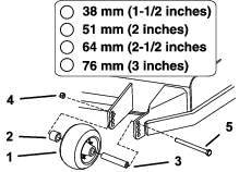
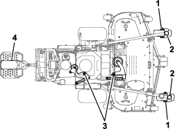
Lubrication Chart Fitting Locations Initial Pumps Number of Places Service Interval 1. Front Caster Wheel Hubs *0 2 *Yearly 2. Front Caster Pivots *0 2 *Yearly 3. Idler Pivots (Mower Deck) and Generator 1 1 Yearly 4. Sulky Wheel Hub 0 1 Yearly * See step 4 for special lubrication instructions on the front caster pivots and the Greasing the Caster Wheel Hubs section for special lubrication instructions on the front casters wheel hubs.
-
Lubricate the front caster pivots once a year. Remove the hex plug and cap. Thread the grease zerk into the hole and pump with grease until it oozes out around the top bearing. Remove the grease zerk and thread the plug back in. Place the cap back on.
Greasing the Caster Wheel Hubs
| Maintenance Service Interval | Maintenance Procedure |
|---|---|
| Yearly |
|
-
Park the machine on a level surface, disengage the PTO, and move the motion control levers outward to the PARK position.
-
Shut off the machine, remove the key, and wait for all moving parts to stop before leaving the operating position.
-
Remove caster wheel from caster forks.
-
Remove seal guards from the wheel hub.
-
Remove one of the spacer nuts from the axle assembly in the caster wheel. Note that thread locking adhesive has been applied to lock the spacer nuts to the axle. Remove the axle (with the other spacer nut still assembled to it) from the wheel assembly.
-
Pry out seals, and inspect bearings for wear or damage and replace if necessary.
-
Pack the bearings with a NLGI grade #1 multi-purpose grease.
-
Insert 1 bearing and 1 new seal into the wheel.
Note: Seals (Toro Part No. 103-0063) must be replaced.
-
If the axle assembly has had both spacer nuts removed (or broken loose), apply a thread locking adhesive to one spacer nut and thread onto the axle with the wrench flats facing outward. Do not thread the spacer nut all of the way onto the end of the axle. Leave approximately 3 mm (1/8 inch) from the outer surface of the spacer nut to the end of the axle inside the nut.
-
Insert the assembled nut and axle into the wheel on the side of the wheel with the new seal and bearing.
-
With the open end of the wheel facing up, fill the area inside the wheel around the axle full of NLGI grade #1 multi-purpose grease.
-
Insert the second bearing and new seal into the wheel.
-
Apply a thread locking adhesive to the 2nd spacer nut and thread onto the axle with the wrench flats facing outward.
-
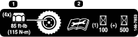
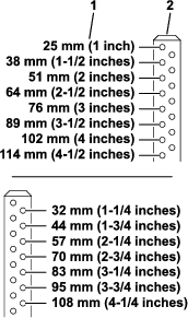
Torque the nut to 8 to 9 N∙m (75 to 80 in-lb), loosen, then torque again to 2 to 3 N∙m (20 to 25 in-lb). Make sure the axle does not extend beyond either nut.
-
Install the seal guards over the wheel hub and insert wheel into caster fork. Install the caster bolt and tighten nut fully.
Important: To prevent seal and bearing damage, check the bearing adjustment often. Spin the caster tire. The tire should not spin freely (more than 1 or 2 revolutions) or have any side play. If the wheel spins freely, adjust torque on spacer nut until there is a slight amount of drag. Reapply thread-locking adhesive.
Engine Maintenance
Important: Refer to your engine owner’s manual for additional maintenance procedures.
Engine Safety
Warning
The engine can become very hot, especially the muffler and exhaust components. Touching a hot engine can cause severe burns.
Allow the engine to cool completely before service or making repairs around the engine area.
Do not change the engine governor setting or overspeed the engine.
Servicing the Air Cleaner
| Maintenance Service Interval | Maintenance Procedure |
|---|---|
| Every 250 hours |
|
| Every 500 hours |
|
-
Park the machine on a level surface, disengage the PTO, and move the motion control levers outward to the PARK position.
-
Shut off the machine, remove the key, and wait for all moving parts to stop before leaving the operating position.
-
See the engine owner's manual for maintenance instructions.
Checking the Engine-Oil Level
| Maintenance Service Interval | Maintenance Procedure |
|---|---|
| Before each use or daily |
|
-
Park the machine on a level surface, shut off the machine, and wait for all moving parts to stop.
-
Check with the engine cold.
-
Clean the area around dipstick. Remove the dipstick and wipe oil off. Reinsert the dipstick according to the engine manufacturer's recommendations. Remove the dipstick and read the oil level.
-
If the oil level is low, wipe off the area around the oil fill cap, remove the cap and fill to the FULL mark on the dipstick. Toro 4-Cycle Engine Oil is recommended; refer to the Engine Owner's manual for an appropriate API rating and viscosity. Do not overfill.
Important: Do not operate the engine with the oil level below the LOW (or ADD) mark on the dipstick, or over the FULL mark.
Changing the Engine Oil
| Maintenance Service Interval | Maintenance Procedure |
|---|---|
| After the first 5 hours |
|
| Every 100 hours |
|
-
Park the machine on a level surface, disengage the PTO, and move the motion control levers outward to the PARK position.
-
Shut off the machine, remove the key, and wait for all moving parts to stop before leaving the operating position.
-
Drain oil while the engine is warm from operation.
-
The oil drain hose is located on the left-hand side of engine. Place pan under the machine to catch oil. Remove the plug from end of drain hose. Allow the oil to drain and replace the oil drain plug. Torque the plug to 27 to 32 N∙m (20 to 24 ft-lb).
-
Replace the oil filter every other oil change. Clean around oil filter and unscrew filter to remove. Before reinstalling new filter, apply a thin coating of Toro 4-Cycle Engine Oil on the surface of the rubber seal. Turn filter clockwise until rubber seal contacts the filter adapter then tighten filter an additional 1/2 to 3/4 turn.
-
Clean around the oil fill cap and remove the cap. Fill to the specified capacity and replace the cap.
-
Use oil recommended in Checking the Engine-Oil Level. Do not overfill. Start the engine and check for leaks. Shut off the engine and check the oil level again.
Checking the Spark Plugs
| Maintenance Service Interval | Maintenance Procedure |
|---|---|
| Every 160 hours |
|
Remove the spark plugs, check condition and reset gaps, or replace with new spark plugs. See the engine owner's manual.
Checking the Spark Arrester
| Maintenance Service Interval | Maintenance Procedure |
|---|---|
| Every 50 hours |
|
Warning
Hot exhaust-system components may ignite fuel vapors even after you shut off the engine. Hot particles exhausted during engine operation may ignite flammable materials, resulting in personal injury or property damage.
Do not refuel or run the engine unless the spark arrester is installed.
-
Park the machine on a level surface, disengage the PTO, and move the motion control levers outward to the PARK position.
-
Shut off the machine, remove the key, and wait for all moving parts to stop before leaving the operating position.
-
Wait for the muffler to cool.
-
If you see any breaks in the screen or welds, replace the arrester.
-
If the screen is plugged, remove the arrester, shake loose particles out of the arrester, and clean the screen with a wire brush (soak the screen in solvent if necessary).
-
Install the arrester on the exhaust outlet.
Fuel System Maintenance
Danger
In certain conditions, fuel is extremely flammable and highly explosive. A fire or explosion from fuel can burn you and others and can damage property.
Refer to Fuel Safety for a complete list of fuel related precautions.
Changing the Fuel Filter
Service Interval: As required
A fuel filter is installed between the fuel tank and the engine. Replace when necessary.
Note: Reinstall the fuel line hoses and secure them with plastic ties as originally routed to keep the lines away from components that could cause damage.
Electrical System Maintenance
Checking the Battery Charge–
Service Interval: As required
Allowing batteries to stand for an extended period of time without recharging them will result in reduced performance and service life. To preserve optimum battery performance and life, recharge batteries in storage when the open circuit voltage drops to 12.1 V.
Note: To prevent damage due to freezing, batteries should be fully charged before putting away for winter storage.
Charge batteries in an open, well-ventilated area away from spark and flames. Unplug the charger before connecting or disconnecting from the battery. Wear protective clothing and use insulated tools.
Danger
Charging or jump-starting the battery may produce explosive gases. Battery gases can explode, causing serious injury.
-
Keep sparks, flames, or cigarettes away from the battery.
-
Ventilate when charging or using the battery in an enclosed space.
-
Make sure that the battery venting path is always open once the battery is filled with acid.
-
Always shield your eyes and face from battery.
Danger
Battery electrolyte contains sulfuric acid, which is poisonous and can cause severe burns. Swallowing electrolyte can be fatal or can cause severe burns if it touches skin.
-
Wear safety glasses to shield eyes, and wear rubber gloves to protect your skin and clothing when handling electrolyte.
-
Do not swallow electrolyte.
-
In the event of an accident, flush with water and call a doctor immediately.
Caution
If the ignition is in the ON position, there is potential for sparks and engagement of components. Sparks could cause an explosion, or moving parts could accidentally engage and cause personal injury.
Ensure that the ignition switch is in the OFF position before charging the battery.
-
12 V System
The battery voltage will be displayed on the message display if the ignition key is turned to the ON position for a few seconds. You can also use a digital voltmeter with the key in the ON position and the engine turned off. Charge the battery to bring it up to a charge of 12.1 V or greater.
-
48 V System
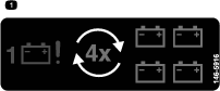
With the engine turned off and the key in the ON position, check each battery individually with a digital voltmeter. Charge each battery individually to bring it up to a charge of 12.1 V or greater. All four batteries need to be charged to a minimum of 12.1 V, and need to be within 0.3 V of each other. If any of the batteries in the pack cannot meet these requirements, all 4 batteries must be replaced at the same time.
Important: When replacing the 48 Volt battery pack, use 4 identical Toro batteries (P/N 142-7345). Charge each battery individually to a minimum of 12.1 V and ensure each battery is within 0.3 V of each other before installing. Failure to do so will reduce the life of the battery pack.
Important: In order to prevent damage to the battery, use an automatic 12 volt smart charger approved for use with AGM type batteries with an output of 3.5 A or less. Make sure the negative battery cable is disconnected before charging and that the charger is set to the correct mode for 12 volt AGM batteries.
Important: For EFI machines: Unplug the harness from the ECU before performing any welding on the equipment.
Recommended Jump Starting Procedure–
Caution
Corrosion or loose connections can cause unwanted electrical voltage spikes at anytime during the jump starting procedure.
Do not attempt to jump start with loose or corroded battery terminals or damage to the engine or EFI may occur.
Danger
Jump starting a weak battery that is cracked, frozen, has low electrolyte level, or an open/shorted battery cell, can cause an explosion resulting in serious personal injury.
Do not jump start a weak battery if these conditions exist.
Caution
Connecting the jumper cables incorrectly (wrong polarity) can immediately damage the electrical and/or EFI system.
Be certain of battery terminal polarity and jumper cable polarity when hooking up batteries.
Warning
Batteries contain acid and produce explosive gases.
-
Shield the eyes and face from the batteries at all times.
-
Do not lean over the batteries.
-
Check the weak battery for terminal corrosion (white, green, or blue “snow”), it must be cleaned off prior to jump starting. Clean and tighten connections as necessary.
-
Make sure the booster is a good and fully charged lead acid battery at 12.6 V or greater. Use properly sized jumper cables (4 to 6 AWG) with short lengths to reduce voltage drop between systems. Make sure the cables are color coded or labeled for the correct polarity.
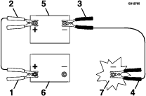
Note: The following instructions are adapted from the SAE J1494 Rev. Dec. 2001 – Battery Booster Cables – Surface Vehicle Recommended Practice (SAE – Society of Automotive Engineers).
Note: Be sure the vent caps are tight and level. Place a damp cloth, if available, over any vent caps on both batteries. Be sure the vehicles do not touch and that both electrical systems are off and at the same rated system voltage. These instructions are for negative ground systems only.
-
Connect the positive (+) cable to the positive (+) terminal of the discharged battery that is wired to the starter or solenoid as shown in Figure 29.
-
Connect the other end of the positive cable to the positive terminal of the booster battery.
-
Connect the black negative (–) cable to the other terminal (negative) of the booster battery.
-
Make the final connection on the engine block of the stalled vehicle (not to the negative post) away from the battery. Stand back.
-
Start the vehicle and remove the cables in the reverse order of connection (the engine block (black) connection is the first to disconnect).
Note: A malfunctioning machine battery may cause the charging voltage to exceed 18.5 V. The engine will turn off if there is a charge above 18.5 V. Turn the ignition switch off, then on again to reset the engine before restarting the machine.
Drive System Maintenance
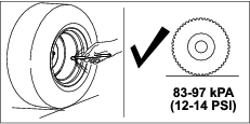
Checking the Tire Pressure
| Maintenance Service Interval | Maintenance Procedure |
|---|---|
| Every 40 hours |
|
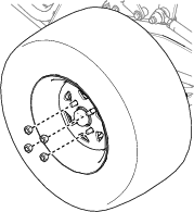
Checking the Wheel-Lug Nuts
| Maintenance Service Interval | Maintenance Procedure |
|---|---|
| After the first 100 hours |
|
Check and torque the wheel lug nuts to 108 to 122 N∙m (80 to 90 ft-lb).
Changing the Transmission Fluid
| Maintenance Service Interval | Maintenance Procedure |
|---|---|
| After the first 50 hours |
|
| Every 500 hours |
|
Fluid type: Toro Synthetic HV Electric Motor Drive Oil
Capacity: 150 ml (5 fl oz)
-
Park the machine on a level surface, disengage the PTO, and move the motion control levers outward to the PARK position.
-
Shut off the machine, remove the key, and wait for all moving parts to stop before leaving the operating position.
-
Remove the tire.
-
Place a drain pan under the transmission.
-
Remove the top plug and bottom plug. Allow the fluid to drain.
-
Install the bottom plug and torque it to 7 to 8 N∙m (62 to 70 in-lb).
-
Remove a side plug.
-
Add fluid, as specified at the beginning of this procedure, through the top hole until the level reaches the side plug opening.
-
Install the top plug and side plug. Torque them to 7 to 8 N∙m (62 to 70 in-lb).
-
Install the tire and torque the lug nuts to 108 to 122 N∙m (80 to 90 ft-lb).
-
Repeat for the other transmission.
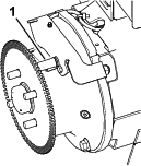
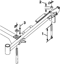
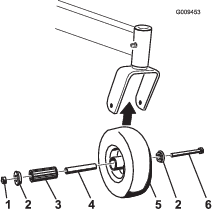
Servicing the Caster Wheels and Bearings
The caster wheels rotate on a roller bearing supported by a spanner bushing. If the bearing is kept well lubricated, wear will be minimal. Failure to keep the bearing well lubricated causes rapid wear. A wobbly caster wheel usually indicates a worn bearing.
-
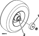
Remove the locknut and wheel bolt holding the caster wheel to the caster fork (Figure 34).
-
Remove 1 bushing, then pull the spanner bushing and roller bearing out of the wheel hub (Figure 34).
-
Remove the other bushing from the wheel hub and clean any grease and dirt from the wheel hub (Figure 34).
-
Inspect the roller bearing, bushings, spanner bushing and the inside of the wheel hub for wear.
Note: Replace any damaged or worn parts (Figure 34).
-
Place 1 bushing into the wheel hub (Figure 34).
-
Grease the roller bearing and spanner bushing, and slide them into the wheel hub (Figure 34).
-
Place the second bushing into the wheel hub (Figure 34).
-
Install the caster wheel into the caster fork and secure it with the wheel bolt and locknut (Figure 34).
-
Tighten the locknut until the spanner bushing bottoms against the inside of the caster forks (Figure 34).
-
Grease the fitting on the caster wheel.
Belt Maintenance
Inspecting the Belts
| Maintenance Service Interval | Maintenance Procedure |
|---|---|
| Every 40 hours |
|
-
Park the machine on a level surface, disengage the PTO, and move the motion control levers outward to the PARK position.
-
Shut off the machine, remove the key, and wait for all moving parts to stop before leaving the operating position.
-
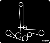
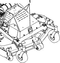
Remove the 2 mower-deck belt shields to check the primary and secondary belt condition.
-
Look under the engine deck to check the generator-drive belt condition.
-
Check all idler arms to be sure that they pivot freely.
Replace the belts if they are worn. The signs of a worn belt include squealing while the belt is rotating; the blades slipping while cutting grass; and frayed edges, burn marks, and cracks on the belt.
Controls System Maintenance
Adjusting the Motion-Control Levers
If the motion-control levers do not align, adjust the motion-control levers.
-
Park the machine on a level surface, disengage the PTO, and move the motion-control levers outward to the PARK position.
-
Shut off the machine, remove the key, and wait for all moving parts to stop before leaving the operating position.
-
Turn the battery-disconnect switch to the OFF position.
-
Push the motion control levers down out of the PARK position.
-
Rotate the CAM to the point that holds the lever at the highest location while still being able to move the full forward position.
-
Verify that the lever does not rub on the edge of the T-box as this could cause it to bind.
-
Tighten the adjustment CAM.
-
When released from full forward position, the lever should return to the neutral location freely.
Mower Deck Maintenance
Blade Safety
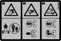
A worn or damaged blade can break and a piece could be thrown toward you or bystanders, resulting in serious personal injury or death.
-
Inspect the blades periodically for excessive wear or damage.
-
Use care when checking the blades. Wear gloves and use caution when servicing them. Only replace the blades; never straighten or weld them.
-
On multi-bladed machines, take care as rotating 1 blade can cause other blades to rotate.
Servicing the Cutting Blades
Before Inspecting or Servicing the Blades
-
Park the machine on a level surface, disengage the PTO, and move the motion control levers outward to the PARK position.
-
Shut off the machine, remove the key, wait for all moving parts to stop before leaving the operating position, and disconnect the spark-plug wires from the spark plugs..
Inspecting the Blades
| Maintenance Service Interval | Maintenance Procedure |
|---|---|
| Before each use or daily |
|
-
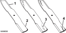
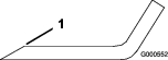
Inspect the cutting edges (Figure 35).
-
If the edges are not sharp or have nicks, remove and sharpen the blade; refer to Sharpening the Blades.
-
Inspect the blades, especially in the curved area.
-
If you notice any cracks, wear, or a slot forming in this area, immediately install a new blade (Figure 35).
Checking for Bent Blades
-
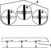
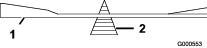
Rotate the blades until the ends face forward and backward.
-
Measure from a level surface to the cutting edge, position A, of the blades (Figure 36).
-
Rotate the opposite ends of the blades forward.
-
Measure from a level surface to the cutting edge of the blades at the same position as in step 2 above.
Note: The difference between the dimensions obtained in steps 2 and 3 must not exceed 3 mm (1/8 inch).
Note: If this dimension exceeds 3 mm (1/8 inch), replace the blade.
Warning
A blade that is bent or damaged could break apart and could critically injure you or bystanders.
-
Always replace a bent or damaged blade with a new blade.
-
Do not file or create sharp notches in the edges or surfaces of the blade.
-
Removing and Installing the Blades
| Maintenance Service Interval | Maintenance Procedure |
|---|---|
| Yearly |
|
-
Park the machine on a level surface, disengage the PTO, and move the motion control levers outward to the PARK position.
-
Shut off the machine, remove the key, and wait for all moving parts to stop before leaving the operating position.
-
Lift the deck and secure in the raised position; refer to Adjusting the Height of Cut.
-
Inspect the blades and sharpen or replace as required.
-
Reinstall the blades (if they were removed) in the following order:
-
Install the bushing through blade with bushing flange on bottom (grass) side of blade.

-
Install the bushing/blade combo into spindle.
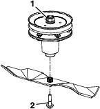
-
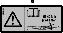
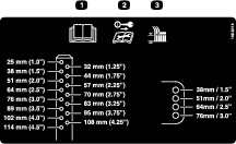
Apply lubricant to threads of blade bolt as needed to prevent seizing. Copper-based anti-seize preferable. Grease acceptable substitute. Install blade bolt finger tight. Place wrench on the top spindle nut then torque the blade bolts to 75 to 81 N∙m (55 to 60 ft-lb).
Warning
Incorrect installation of the blade or components used to retain the blade can be dangerous. Failure to use all original components and assembled as shown could allow a blade or blade component to be thrown out from under the deck resulting in serious personal injury or death.
Always install the original Toro blades, blade bushings, and blade bolts as shown.
-
Sharpening the Blades
-
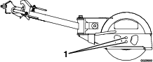
Use a file to sharpen the cutting edge at both ends of the blade (Figure 39).
Note: Maintain the original angle.
Note: The blade retains its balance if the same amount of material is removed from both cutting edges.
-
Check the balance of the blade by putting it on a blade balancer (Figure 40).
Note: If the blade stays in a horizontal position, the blade is balanced and can be used.
Note: If the blade is not balanced, file some metal off the end of the sail area only (Figure 39).
-
Repeat this procedure until the blade is balanced.
Sulky Maintenance
Inspecting the Sulky
| Maintenance Service Interval | Maintenance Procedure |
|---|---|
| Before each use or daily |
|
-
Park the machine on a level surface, disengage the PTO, and move the motion control levers outward to the PARK position.
-
Shut off the machine, remove the key, and wait for all moving parts to stop before leaving the operating position.
-
Inspect for loose hardware. Tighten any loose hardware.
-
Inspect for wear or damage daily. Replace or repair worn parts as needed before operating.
Checking the Sulky for Buildup
| Maintenance Service Interval | Maintenance Procedure |
|---|---|
| Before each use or daily |
|
Check for dirt/mud buildup between tire and fender. Remove buildup before operating.
Note: You can wash the sulky with mild detergent and water. Do not pressure wash the machine.
Adjusting the Tire
To obtain additional ground clearance, the platform wheel can be repositioned (see Figure 41).
Note: To achieve more ground clearance for higher cutting heights, raise the platform by using the lower wheel adjustment hole.
Adjustments
Important: Park the machine on a level surface, disengage the PTO, move the motion control levers outward to the PARK position, shut off the machine, remove the key, and wait for all moving parts to stop before servicing, cleaning, or making any adjustments to the unit.
Generator Drive-Belt Tension
The generator drive belt is self-tensioning, so there is no necessary adjustment.
Deck Belt Tension
The deck belt is self-tensioning, so there is no necessary adjustment.
Electric Clutch Adjustment
There is no necessary adjustment for the electric clutch.
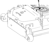
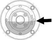
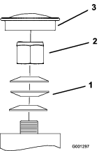
Adjusting the Caster-Pivot Bearings
| Maintenance Service Interval | Maintenance Procedure |
|---|---|
| Every 500 hours |
|
-
Park the machine on a level surface, disengage the PTO, and move the motion control levers outward to the PARK position.
-
Shut off the machine, remove the key, and wait for all moving parts to stop before leaving the operating position.
-
Remove the dust cap from the caster and tighten the locknut (Figure 42).
-
Tighten the locknut until the spring washers are flat, and then back off a 1/4 turn to properly set the preload on the bearings (Figure 42).
Important: Make sure that the spring washers are installed correctly as shown in Figure 42.
-
Install the dust cap (Figure 42).
Cleaning
Cleaning and Storage Safety
-
Park the machine on a level surface, disengage the drives, engage the parking brake, shut off the engine, remove the key, and disconnect the spark-plug wire. Wait for all moving parts to stop before leaving the operator’s position. Allow the machine to cool before servicing, adjusting, fueling, cleaning, or storing.
-
Clean grass and debris from the cutting unit, muffler, drives, grass catcher, and engine compartment to prevent fires.
-
Allow the machine to cool before storing the machine in any enclosure. Do not store the machine or fuel container, or refuel, near an open flame, spark, or pilot light, such as those on a water heater or other appliance.
Cleaning Debris From the Machine
| Maintenance Service Interval | Maintenance Procedure |
|---|---|
| Before each use or daily |
|
-
Park the machine on a level surface, disengage the PTO, and move the motion control levers outward to the PARK position.
-
Shut off the machine, remove the key, and wait for all moving parts to stop before leaving the operating position.
-
Clean off any oil, debris, or grass build-up on the machine and cutting deck, especially under deck belt shields, around the fuel tank, around engine and exhaust area.
Important: You can wash the machine with mild detergent and water. Do not pressure wash the machine. Avoid excessive use of water, especially near the control panel, around the engine, generator, ACS tower, and motors.
Cleaning the Engine and Exhaust System Area
| Maintenance Service Interval | Maintenance Procedure |
|---|---|
| Before each use or daily |
|
Caution
Excessive debris around the engine cooling air intake and exhaust system area can cause the engine, exhaust area, and hydraulic system to overheat, which can create a fire hazard.
Clean all debris from the engine and exhaust system area.
-
Park the machine on a level surface, disengage the PTO, and move the motion control levers outward to the PARK position.
-
Shut off the machine, remove the key, and wait for all moving parts to stop before leaving the operating position.
-
Clean all debris from rotating engine air intake screen, around engine shrouding, and exhaust system area.
-
Wipe up any excessive grease or oil around the engine and exhaust system area
Cleaning Grass Build-Up Under the Deck
| Maintenance Service Interval | Maintenance Procedure |
|---|---|
| Before each use or daily |
|
-
Park the machine on a level surface, disengage the PTO, and move the motion control levers outward to the PARK position.
-
Shut off the machine, remove the key, and wait for all moving parts to stop before leaving the operating position.
-
Raise deck to the transport (maximum cutting height) position. Lift the front of unit and support the machine using jack stands or equivalent support.
-
Clean out any grass build-up from underside of deck and in discharge deflector.
Disposing of Waste
Oil and Fluid Disposal
Engine oil and hydraulic fluid are both pollutants to the environment. Dispose of these at a certified recycling center according to your state and local regulations.
Battery Disposal
Danger
Battery electrolyte contains sulfuric acid, which is poisonous and can cause severe burns. Swallowing electrolyte can be fatal or can cause severe burns if it touches skin.
-
Wear safety glasses to shield eyes, and wear rubber gloves to protect your skin and clothing when handling electrolyte.
-
Do not swallow electrolyte.
-
In the event of an accident, flush with water and call a doctor immediately.
Federal law states that batteries should not be placed in the garbage. Management and disposal practices must be within relevant federal, state, or local laws.
If a battery is being replaced or if the unit containing the battery is no longer operating and is being scrapped, take the battery to a local certified recycling center. If no local recycling is available return the battery to any certified battery reseller.