Installation
Preparing the Machine
-
Park the machine on a level surface.
-
Engage the parking brake.
-
Raise the cutting unit to the TRANSPORT position; refer to your Operator’s Manual.
-
Shut off the machine and remove the key.
-
Turn the battery-disconnect switch to the OFF position; refer to the traction unit Operator’s Manual.
-
Rotate the cutting unit to the SERVICE position; refer to your Operator’s Manual.
Removing the Blades
Remove the blades from the cutting unit; refer to the blade removal procedure in the cutting unit Operator’s Manual.
Removing the Existing Baffles
Note: In the steps below, the bolts are threaded into the mower deck. Remove the nuts before removing the bolts.
-
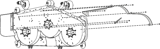
Remove the 2 flange nuts that secure the baffles in place (Figure 1).
-
Remove the 2 bolts and 2 nuts from the adjustable flow baffle (Figure 1).
-
Remove the 3 bolts and 3 nuts that secure the baffles in place (Figure 1).
Note: Retain the baffles and fasteners for use when changing back to side-discharge mode.
Installing the Discharge Cover Plate
Parts needed for this procedure:
| Discharge cover plate | 1 |
| Carriage bolt (5/16 x 7/8 inch) | 1 |
| Flange nut (5/16 inch) | 1 |
| Carriage bolt (3/8 x 1-1/4 inches) | 2 |
| Locknut (3/8 inch) | 2 |
-
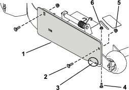
Secure the discharge cover plate to the outside of the mounting bracket using 2 carriage bolts (3/8 x 1-1/4 inches) and 2 locknuts (3/8 inch) as shown in Figure 2.
-
Secure the tab to the inside of the mower deck using 1 carriage bolt (5/16 x 7/8 inch) and 1 flange nut (5/16 inch) as shown in Figure 2.
Installing the Recycler Baffles
Parts needed for this procedure:
| Left baffle | 1 |
| Center baffle | 1 |
| Right baffle | 1 |
| Carriage bolt (3/8 x 1 inch) | 7 |
| Locknut (3/8 inch) | 8 |
| Hex-washer-head bolt (3/8 inch) | 2 |
| Flange nut (3/8 inch) | 1 |
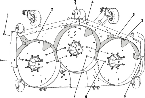
Note: Loosely install the baffles to align the baffles with all the holes in the mower deck (Figure 3).
-
Position the right baffle into the mower deck.
-
Loosely install the right baffle to the discharge plate using 1 carriage bolt (3/8 x 1 inch) and 1 locknut (3/8 inch) as shown in Figure 3.
-
Loosely install the right baffle to the mower deck using 1 carriage bolt (3/8 x 1 inch) and 1 flange nut (3/8 inch) as shown in Figure 3.
-
Position the left baffle into the mower deck.
-
Loosely install the left baffle to the mower deck using 1 carriage bolt (3/8 x 1 inch), 1 hex-washer-head bolt (3/8 x 1 inch), and 2 locknuts (3/8 inch) as shown in Figure 3.
-
Position the center baffle into the mower deck.
-
Loosely install the center baffle to the right baffle and left baffle using 4 carriage bolts (3/8 x 1 inch) and 4 locknuts (3/8 inch) as shown in Figure 3.
-
Loosely install the center baffle to the mower deck using 1 hex-washer-head bolt (3/8 x 1 inch) and 1 locknut (3/8 inch) as shown in Figure 3.
Installing the Kickers
Parts needed for this procedure:
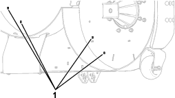
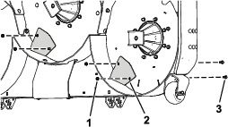
| Kicker | 2 |
| Carriage bolt (5/16 x 7/8 inch) | 4 |
| Flange nut (5/16 inch) | 4 |
Installing the Recyler Blades
Parts needed for this procedure:
| Recycler blade | 3 |
Install the blades to the cutting unit; refer to the blade installation procedure in the cutting unit Operator’s Manual.
Tightening the Hardware
-
Tighten all nuts and bolts for the baffles.
-
Rotate the blades and ensure that there is clearance between the blades and the baffles. If there is not, loosen the baffle(s) until there is clearance and then secure the baffle(s).
Completing the Installation
Rotate the cutting unit to the MOWING position; refer to your Operator’s Manual.
Operation
Understanding Energy Consumption
A Recycler Kit (equipped on the cutting unit) may increase energy use. To extend operating time, do at least one of the following options:
-
Remove the existing recycler blades and install low-sail blades; refer to the blade removal and installation procedure in your cutting unit Operator’s Manual.
-
Reduce the cutting-unit blade speed; refer to the blade speed instructions in the traction unit Operator’s Manual.