Seat Belt Alarm Kit

Groundsmaster® 3200 or 3300 Series Traction Unit with ROPS

Safety

Safety and Instructional Decals

Image
Safety decals and instructions are easily visible to the operator and are located near any area of potential danger. Replace any decal that is damaged or missing.
Decal Part: 164-7051
Graphic
s_decal164-7051
  1.  Alarm

Installation

Preparing the Machine

Caution
If you leave the key in the ignition switch, someone could accidently start the engine and seriously injure you or bystanders.
Remove the key from the ignition switch before you do any maintenance.
 
  1. Park the machine on a level surface, disengage the PTO, lower the cutting units, and engage the parking brake.
  2. Shut off the engine, remove the key, wait for all moving parts to stop, and allow the engine to cool.

Disconnecting the Battery

Danger
Battery electrolyte contains sulfuric acid, which is fatal if consumed and causes severe burns.
  • Do not drink electrolyte and avoid contact with skin, eyes, or clothing.
  • Wear safety glasses and rubber gloves.
  • Fill the battery where clean water is always available for flushing the skin.
 
  1. Depending on the machine model, open either the screen or the hood to access the battery.
  2. Graphic
    G416225
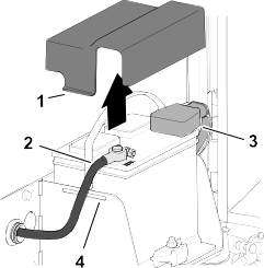
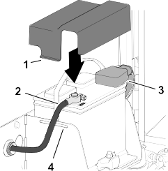
  3. Remove the cover from the battery tray by pressing the sides of the battery cover.
  4. Disconnect the negative battery cable .
  5. Slide the insulator cover off the positive battery-cable clamp, and disconnect the positive battery cable.
  6. Close and latch the screen/hood.

Tilting the Seat

    Graphic
    G443836
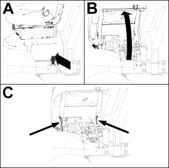
  1. Unlatch the seat base .
  2. Tilt the seat and base open .
  3. Support it with the prop rods .

Replacing the Seat Belt Buckle

Parts Required
1
Seat belt buckle (part no. 161-8972)
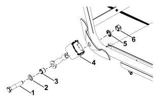
  1. Remove the existing seat belt buckle from the seat base.
    Graphic
    G609781
    1. Bolt
    2. Lock washer
    3. Large spacer
    4. Seat belt buckle
    5. Small spacer
    6. Nut
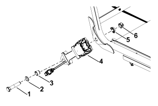
  2. Install the new seat belt buckle and secure using the previously removed hardware.
    Graphic
    G609780
    1. Bolt
    2. Lock washer
    3. Large spacer
    4. Seat belt buckle
    5. Small spacer
    6. Nut
  3. Torque the bolt to 55 N∙m (41 ft-lb).

Installing the Alarm

Parts Required
1
Alarm
1
Alarm decal
1
Plastic nut
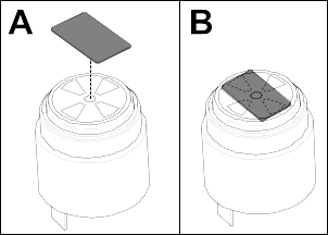
  1. Install the alarm decal on the top of the alarm in the orientation shown.
    Graphic
    G607151
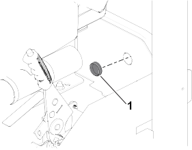
  2. Insert the plastic nut into from inside the machine as shown.
    Graphic
    G610360
    1. Plastic nut
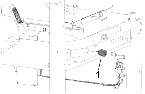
  3. Thread the alarm into the plastic nut from the back of the machine.
    Graphic
    G610371
    1. Alarm
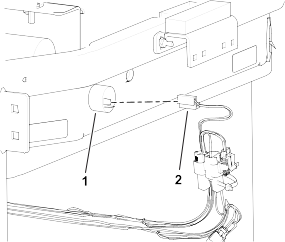
  4. Connect the 2-pin connector on the wire harness to the alarm.
    Graphic
    G610926
    1. Alarm
    2. 2–pin connector
  5. Reinstall the parking brake cover.

Installing the Proximity Sensor

Parts Required
1
Proximity sensor
1
Sensor mounting bracket
1
Bolt (1/2 x 3-1/2 inches)
1
Nut (1/2 inch)
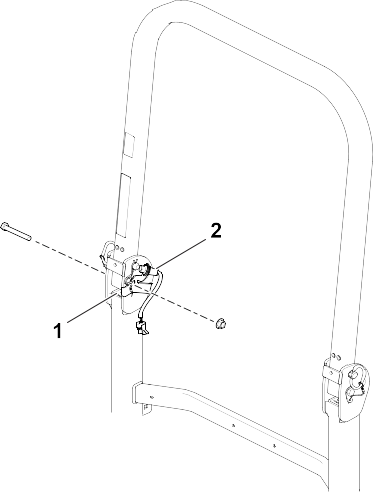
Note: ROPS must be fully upright during installation.
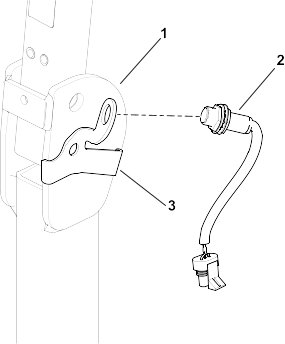
  1. Install the proximity sensor to the sensor mounting bracket as shown.
    Graphic
    G610982
    1. ROPS
    2. Proximity Sensor
    3. Sensor Mounting Bracket
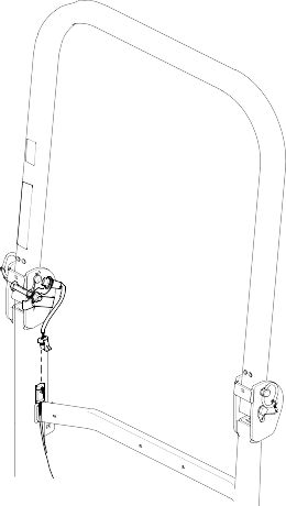
  2. Install the proximity sensor and sensor mounting bracket to the ROPS with 1 bolt (1/2 x 3-1/2 inches) and 1 nut (1/2 inch).
    Graphic
    G610979
    1. Sensor mounting bracket
    2. Proximity sensor
  3. Adjust the sensor so that it is 5 mm or less from the ROPS pin.
  4. Install the ROPS wire harness connector on the sensor.
    Image
  5. Ensure that the wire harness is not in contact with moving parts, pinch points, or heat sources.
  6. Discard the old bolt and nut.

Routing the Wire Harness

Parts Required
1
Wire harness
2
Cable tie
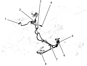
  1. Route the kit wire harness along the machine wire harness.
    Graphic
    G610917
    1. Wire harness connector
    2. Wire harness connector
    3. ROPS wire harness connector
    4. Seat belt buckle wire harness connector
    5. Wire harness connector (expansion port)
    6. Audio alarm wire harness connector
    7. Wire harness connector
    8. IMU wire harness connector
  2. Confirm that all connections are secured to the kit wire harness:
    1. Connect the 3-pin connector on the harness to the ROPS connector .
    1. Connect the harness to the seat belt buckle.
    1. Connect the 3-pin connector on the harness to the expansion port on the main wire harness.
    1. Connect the 12-pin connector on the harness to the IMU .
    1. Connect remaining wire harness connections as needed.
  3. Secure the kit wire harness under the rear of the seat with 2 cable ties to the wire harness.
  4. Ensure that the wire harness is not in contact with moving parts, pinch points, or heat sources.

Connecting the Battery

    Graphic
    G416226
  1. Install the positive battery cable (red) to the positive (+) battery post.
  2. Install the negative battery cable (black) to the negative (-) battery post.
  3. Apply a coat of Grafo 112X (skin-over) grease, Toro Part No. 505-47 to the battery posts and battery-cable clamps.
  4. Slide the rubber boot over the positive battery-cable clamp.
  5. Assemble the cover over the battery, inserting the tabs of the cover into the slots in the battery tray.
  6. Close and latch the screen/hood.

Calibrating the Kit

  1. Move the machine to level ground and ensure that the vehicle is not moved during calibration.
  2. Locate the calibration jumper on the alarm harness located near the IMU.
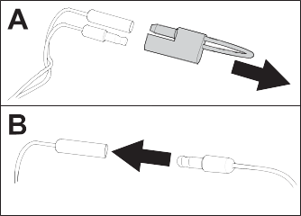
  3. Remove the calibration jumper from the 2 bullet terminals and connect the 2 terminals together.
    Graphic
    G610386
  4. Turn on the machine and allow at least 30 seconds for automatic calibration. Once complete, the InfoCenter will display a calibration confirmation.
    Note: Ensure that the vehicle is not moved during calibration.
  5. Turn off the machine, disconnect the terminals, and install the calibration jumper onto the 2 bullet terminals.

Testing the Alarm Function

  1. Unlatch the seat belt.
  2. Briefly drive the machine in an open area.
  3. Verify that the audible alarm is active.
  4. Verify that the visual alarm icon Image appears on the InfoCenter.