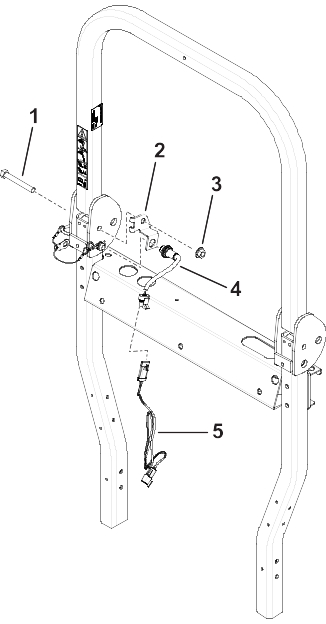
Seat Belt Alarm Kit

Groundsmaster 7210 Series Traction Unit with ROPS

Safety

Safety and Instructional Decals

Image
Safety decals and instructions are easily visible to the operator and are located near any area of potential danger. Replace any decal that is damaged or missing.
Decal Part: 164-7051
Graphic
s_decal164-7051
  1.  Alarm

Installation

Preparing the Machine

  1. Park the machine on a level surface.
  2. Engage the parking brake.
  3. Shut off the machine.
  4. Disconnect the battery; refer to your Operator’s Manual.

Replacing the Seat Belt Buckle

Parts Required
1
Seat belt buckle
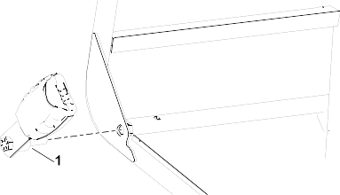
  1. Remove the existing seat belt buckle from the seat base.
  2. Install the new seat belt buckle using the previously removed nut and bolt.
    Graphic
    G607370
  3. Torque the bolt to 55 N∙m (41 ft-lb).
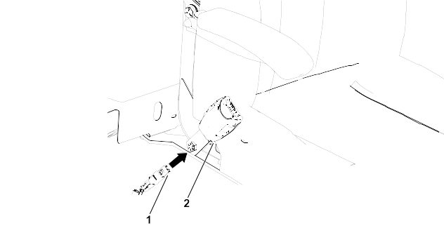
  4. Connect the seat belt buckle to the 2-pin connector .
    Graphic
    G607994

Installing the Alarm

Parts Required
1
Alarm
1
Alarm decal
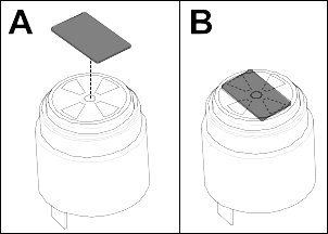
  1. Install the alarm decal on the top of the alarm in the orientation shown.
    Graphic
    G607151
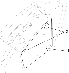
  2. Open the side panel using the latches.
    Graphic
    G610385
    1. Side panel
    2. Latches
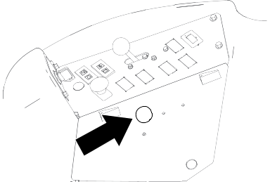
  3. Drill a hole (1-1/10 inches) for the alarm.
    Graphic
    G611148
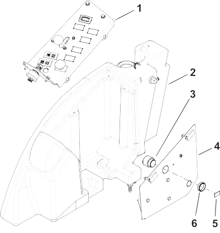
  4. Install the alarm to the side panel.
    Graphic
    G610645
    1. Control panel
    2. Right side of machine
    3. Alarm
    4. Side panel
    5. Alarm decal
    6. Plastic nut

Installing the Inertial Measurement Unit (IMU)

Parts Required
1
IMU
1
IMU bracket
2
Bolt (1/4 x 1-1/4 inches)
2
Bolt (1/4 x 3/4 inch)
4
Nut (1/4 inch)
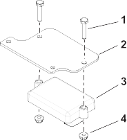
  1. Install the IMU onto the IMU bracket using 2 bolts (1/4 x 1-1/4 inches) and 2 nuts (1/4 inch).
    Graphic
    G610644
    1. Bolt (1/4 x 1-1/4 inches)
    2. IMU bracket
    3. IMU
    4. Nut (1/4 inch)
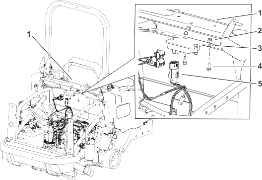
  2. Install the IMU bracket onto the machine using 2 bolts (1/4 x 3/4 inch) and 2 nuts (1/4 inch).
    Graphic
    G610643
    1. Crossmember behind the seat
    2. Nut (1/4 inch)
    3. IMU bracket
    4. Bolt (1/4 x 3/4 inch)
    5. Kit wire harness 12-pin connector

Installing the Proximity Sensor

Parts Required
1
Proximity sensor
1
Sensor bracket
1
Bolt (1/2 x 3-3/4 inches)
1
Nut (1/2 inch)
1
Rollbar wire harness
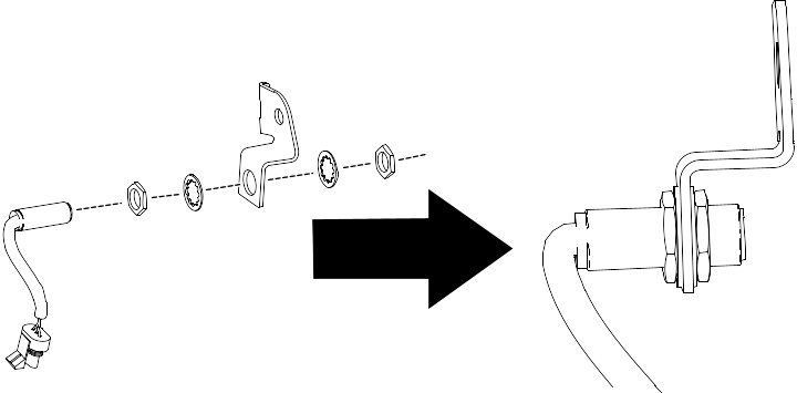
  1. Loosely install the proximity sensor onto the bracket.
    Graphic
    G609357
  2. Secure the sensor bracket to the rollbar using a bolt (1/2 x 3-3/4 inches) and nut (1/2 inch).
    Graphic
    G610646
    1. Bolt (1/2 x 3-3/4 inches)
    2. Sensor bracket
    3. Nut (1/2 inch)
    4. Sensor
    5. Rollbar harness
  3. Adjust the sensor so that it is 5 mm or less from the ROPS pin.
  4. Tighten the hardware on the sensor.
  5. Install the rollbar wire harness to the connector on the sensor.

Routing the Wire Harness

Parts Required
1
Wire harness
2
Cable tie
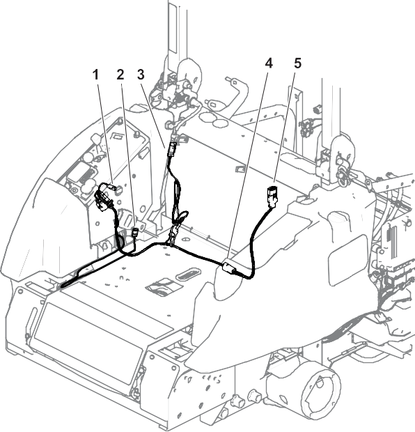
Route the wire harness along the machine wire harness.
  1. Connect the 2-pin connector (P02 AUDIO ALARM) on the harness to the alarm connector.
  2. Connect the 2-pin connector (P05 SEAT BELT SW) on the harness to the seat belt connector.
  3. Connect the 3-pin connector (P12 TO ROPS HARNESS) on the harness to the rollbar harness connector.
  4. Connect the 6-pin connector (P07 TO EXPANSION PORT) on the harness to the expansion port on the main wire harness.
  5. Connect the 12-pin connector (P01 K1 TSM1201) on the harness to the IMU connector.
    Graphic
    G610647
  6. Secure the wire harness with cable ties.

Calibrating the Kit

  1. Move the machine to level ground and ensure that the vehicle is not moved during calibration.
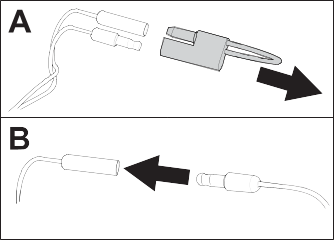
  2. Locate the calibration jumper on the alarm harness located near the IMU.
  3. Remove the calibration jumper from the 2 bullet terminals and connect the 2 terminals together.
    Graphic
    G610386
  4. Turn on the machine and allow at least 30 seconds for automatic calibration. Once complete, the InfoCenter will display a calibration confirmation.
    Note: Ensure that the vehicle is not moved during calibration.
  5. Turn off the machine, disconnect the terminals, and install the calibration jumper onto the 2 bullet terminals.

Testing the Alarm Function

  1. Unlatch the seat belt.
  2. Briefly drive the machine in an open area.
  3. Verify that the audible alarm is active.
  4. Verify that the visual alarm icon Image appears on the InfoCenter.